EP4262407B1 - Système et procédé de transport suspendu à un rail - Google Patents
Système et procédé de transport suspendu à un rail Download PDFInfo
- Publication number
- EP4262407B1 EP4262407B1 EP21830803.9A EP21830803A EP4262407B1 EP 4262407 B1 EP4262407 B1 EP 4262407B1 EP 21830803 A EP21830803 A EP 21830803A EP 4262407 B1 EP4262407 B1 EP 4262407B1
- Authority
- EP
- European Patent Office
- Prior art keywords
- carrier
- carcass
- engaging portion
- free end
- carcass part
- Prior art date
- Legal status (The legal status is an assumption and is not a legal conclusion. Google has not performed a legal analysis and makes no representation as to the accuracy of the status listed.)
- Active
Links
Images


Classifications
-
- A—HUMAN NECESSITIES
- A22—BUTCHERING; MEAT TREATMENT; PROCESSING POULTRY OR FISH
- A22C—PROCESSING MEAT, POULTRY, OR FISH
- A22C17/00—Other devices for processing meat or bones
- A22C17/0093—Handling, transporting or packaging pieces of meat
-
- A—HUMAN NECESSITIES
- A22—BUTCHERING; MEAT TREATMENT; PROCESSING POULTRY OR FISH
- A22B—SLAUGHTERING
- A22B7/00—Slaughterhouse arrangements
- A22B7/001—Conveying arrangements
- A22B7/002—Devices for hanging animal carcasses while being conveyed or stored, e.g. gambrels, hooks
-
- A—HUMAN NECESSITIES
- A22—BUTCHERING; MEAT TREATMENT; PROCESSING POULTRY OR FISH
- A22B—SLAUGHTERING
- A22B7/00—Slaughterhouse arrangements
- A22B7/001—Conveying arrangements
- A22B7/004—Rails for conveying suspended carcasses, e.g. configurations, connections
-
- A—HUMAN NECESSITIES
- A22—BUTCHERING; MEAT TREATMENT; PROCESSING POULTRY OR FISH
- A22B—SLAUGHTERING
- A22B7/00—Slaughterhouse arrangements
- A22B7/001—Conveying arrangements
- A22B7/005—Means for transferring carcasses from a conveying unit to a different one, e.g. hooking, unhooking
-
- B—PERFORMING OPERATIONS; TRANSPORTING
- B65—CONVEYING; PACKING; STORING; HANDLING THIN OR FILAMENTARY MATERIAL
- B65G—TRANSPORT OR STORAGE DEVICES, e.g. CONVEYORS FOR LOADING OR TIPPING, SHOP CONVEYOR SYSTEMS OR PNEUMATIC TUBE CONVEYORS
- B65G17/00—Conveyors having an endless traction element, e.g. a chain, transmitting movement to a continuous or substantially-continuous load-carrying surface or to a series of individual load-carriers; Endless-chain conveyors in which the chains form the load-carrying surface
- B65G17/30—Details; Auxiliary devices
- B65G17/48—Controlling attitudes of load-carriers during movement
- B65G17/485—Controlling attitudes of load-carriers during movement the load carriers being suspended
-
- B—PERFORMING OPERATIONS; TRANSPORTING
- B65—CONVEYING; PACKING; STORING; HANDLING THIN OR FILAMENTARY MATERIAL
- B65G—TRANSPORT OR STORAGE DEVICES, e.g. CONVEYORS FOR LOADING OR TIPPING, SHOP CONVEYOR SYSTEMS OR PNEUMATIC TUBE CONVEYORS
- B65G47/00—Article or material-handling devices associated with conveyors; Methods employing such devices
- B65G47/52—Devices for transferring articles or materials between conveyors i.e. discharging or feeding devices
- B65G47/53—Devices for transferring articles or materials between conveyors i.e. discharging or feeding devices between conveyors which cross one another
-
- B—PERFORMING OPERATIONS; TRANSPORTING
- B65—CONVEYING; PACKING; STORING; HANDLING THIN OR FILAMENTARY MATERIAL
- B65G—TRANSPORT OR STORAGE DEVICES, e.g. CONVEYORS FOR LOADING OR TIPPING, SHOP CONVEYOR SYSTEMS OR PNEUMATIC TUBE CONVEYORS
- B65G47/00—Article or material-handling devices associated with conveyors; Methods employing such devices
- B65G47/52—Devices for transferring articles or materials between conveyors i.e. discharging or feeding devices
- B65G47/60—Devices for transferring articles or materials between conveyors i.e. discharging or feeding devices to or from conveyors of the suspended, e.g. trolley, type
- B65G47/61—Devices for transferring articles or materials between conveyors i.e. discharging or feeding devices to or from conveyors of the suspended, e.g. trolley, type for articles
-
- B—PERFORMING OPERATIONS; TRANSPORTING
- B65—CONVEYING; PACKING; STORING; HANDLING THIN OR FILAMENTARY MATERIAL
- B65G—TRANSPORT OR STORAGE DEVICES, e.g. CONVEYORS FOR LOADING OR TIPPING, SHOP CONVEYOR SYSTEMS OR PNEUMATIC TUBE CONVEYORS
- B65G9/00—Apparatus for assisting manual handling having suspended load-carriers movable by hand or gravity
- B65G9/004—Loading or unloading arrangements
-
- B—PERFORMING OPERATIONS; TRANSPORTING
- B65—CONVEYING; PACKING; STORING; HANDLING THIN OR FILAMENTARY MATERIAL
- B65G—TRANSPORT OR STORAGE DEVICES, e.g. CONVEYORS FOR LOADING OR TIPPING, SHOP CONVEYOR SYSTEMS OR PNEUMATIC TUBE CONVEYORS
- B65G2201/00—Indexing codes relating to handling devices, e.g. conveyors, characterised by the type of product or load being conveyed or handled
- B65G2201/02—Articles
- B65G2201/0202—Agricultural and processed food products
Definitions
- the present invention relates to the transport of four-legged slaughter animal carcass or carcass parts hanging suspended from carriers engaging in openings in leg portions of the carcass or carcass parts. More particularly, it relates to the transfer of a carcass part from one carrier to another carrier.
- the carcass parts may be a half carcass that has been eviscerated and cleaned.
- the carriers used may be of the gambrel type, having two opposed carrier ends pointing away from each other and being tied together with a cross bar.
- the cross bar has a hanging arrangement that cooperates with an overhead transport conveyor system.
- Another type of carrier may be the Euro Hook variant, aka Euro Carrier, having a pointed end and a carrier portion shaped like a fishing carrier.
- the Euro Hook also has a hanging arrangement that cooperates with an overhead transport conveyor system similar to that used for gambrels.
- the single carriers may comply with DIN 5047 (Carriers for meat and other food; tubular track sliding carrier).
- EP1152664B1 (Butina APS) discloses transferring half pig carcasses hanging from each end of a gambrel engaging in first openings in the carcasses whereafter a suspension means, e.g. a single carrier, is attached to engage the calcaneal tendon, thus a second opening in the carcasses as is shown in Figure 5 of EP1152664B1 .
- the gambrel is then removed from the first openings and each carcass half is transported separately away for deboning and other processing. This process is labour intensive, putting a maximum limit on the throughput speed of the system.
- WO2005/099459A1 discloses transferring half carcasses, hanging from carriers of an overhead conveyor, to a horizontal conveyor belt by temporarily gripping and holding the carcass sides, cutting the sinews through and cutting the hind foot/toe to release the rest of the carcass onto the belt.
- This, and variations on this technology is common in the industry, but has the disadvantage that the further deboning has to take place on a horizontal surface with heavy lifts for operators and limited opportunities for automation of processes.
- WO 2020/225152 A1 that is directed to an overhang rail transport system for the transport of four-legged slaughter animal carcass parts hanging suspended from carriers engaging in openings in leg portions of the carcass parts, is considered the closest prior art. Relative to this document, at least the characterizing features of the independent claims are novel.
- One object of the invention is to provide a system and a method for automatic transfer of carcass parts suspended from a first carrier to being suspended from a second carrier.
- the carcass parts may be a half carcass, e.g. from pig, that may have been eviscerated and cleaned.
- the term "carcass part" is also used for a whole animal carcass.
- the first carrier may be an industry standard gambrel having two opposed carrier ends pointing away from each other and being tied together with a cross bar or a single carrier, for example a Euro Hook.
- the second carrier may be a single carrier, for example a Euro Hook.
- Embodiments of the invention preferably seek to mitigate, alleviate or eliminate one or more of the above mentioned disadvantages singly or in any combination.
- an overhang rail transport system comprising a first carrier being transported by a first overhead conveyor in a transport direction and having a first carcass engaging portion, the first carrier being arranged to selectively carry a carcass part by engaging the carcass part with the first carcass engaging portion, a second carrier being transported by a second overhead conveyor and having a second carcass engaging portion, the second carrier being arranged to selectively carry a carcass part by engaging the carcass part with the second carcass engaging portion, a vertical aligning device to align the first carcass engaging portion and the second carcass engaging portion in a vertical direction, a horizontal aligning device to align the first carcass engaging portion and the second carcass engaging portion in a horizontal direction, so that both the first carcass engaging portion and the second carcass engaging portion simultaneously engage the carcass part, a tilting device to tilt the first carcass engaging portion downwards, so that the weight of the carcass part is gradually transferred from the first carcass engaging portion to the second carcass engaging portion, and
- the overhang rail transport system further may further comprise a first processing section having multiple spaced apart first carriers for conveying carcass parts of a four legged slaughter animal, where each of the first carriers has a free end designed to extend through an opening in a leg part of the carcass parts causing the carcass parts to be at least freely hanging, and at least one second processing section having multiple spaced apart second carriers where each of the second carriers has a free end designed to engage with the leg part of the carcass parts causing the carcass part to be at least freely hanging.
- the overhang rail transport system may further have a transfer zone, positioned between the first processing section and the at least one second processing section, and a control device for automatically controlling the movement of the first and the second carriers so that upon arrival at the transfer zone the first and the second carriers are synchronized in movement such that the first carrier moves in a first direction carrying a carcass part through an opening arranged in the leg part and at least one empty second carrier moving in a second direction meet with their respective free ends facing each other.
- Multiple second processing sections may form corresponding multiple transfer zones of the overhang rail transport system, to direct carcass parts from the first carriers to selected second carriers of any of the multiple processing sections. In this way, carcass parts may be classified into different processing lines, for instance.
- the transfer zone is in one embodiment designed such that during movement of the first and the second carriers:
- the at least one second processing section may include a second processing section comprising second type of carriers, a third processing section comprising third type of carriers etc., where each processing section may have different processing steps, e.g. one may be a first type of deboning line, another one may be a second type of deboning line, the third may be a cooling section acting as a buffer etc..
- the transfer zone is further designed so that upon arrival at the transfer zone the height level of the free end of the second carrier is below a height level of the free end of the first carrier such that the decrease in the relative position of the free ends causes the free end of the second carrier to penetrate into the opening at the leg part below the free end of the first carrier.
- the transfer zone is further designed so the relative height level distance between the free end of the first carrier and the free end of the second carrier changes until the height level of the free end of the second carrier is above the height level of the first carrier causing the weight transfer of the carcass part load to the second carrier.
- the overhang rail system may further comprise a guiding device, subsequent to the transfer of the carcass part to the second carrier, to tilt the first carrier and guide the first carrier and/or the carcass part away from the second carrier resulting in that the second carrier being the sole carrier for the carcass part.
- the overhang rail system further may have a guiding device, subsequent to the transfer of the carcass part to the second carrier, to guide the first carrier and/or the carcass part away from the second carrier resulting in that the second carrier becomes the sole carrier for the carcass part.
- the guiding device may have an elongated guiding member arranged relative to the first and second carriers such that the elongated guiding member, e.g. a rod or similar, interacts with the first carrier and/or the carcass part while the first carrier moves in the first direction, the interaction forcing an increase in the relative horizontal distance between the first carrier and the second carrier until a complete separation of the first carrier from the opening in the leg part.
- the elongated guiding member e.g. a rod or similar
- the first carrier may be slideably attached to a first rail guide and the second carrier may be slideably attached to a second rail guide, where the transfer zone is defined via the arrangement of the first and/or the second rail guide causing the change in the relative horizontal distance between the free end of the first carrier and of the free end of the second carrier, and causing the change in the relative height level distance between the free end of the first carrier and the free end of the second carrier.
- the first carrier may be a gambrel like structure comprising free ends at its opposite ends, where each of the opposite ends carries a carcass part, where the at least one second processing section includes two second processing sections, where the synchronized movement occurs at the opposite ends of the gambrel where empty free ends of second carriers penetrate, e.g. simultaneously, into the respective opening at the leg parts of the carcass parts.
- the carcass parts which may be half carcasses
- the processing steps at the second and third processing sections may include, but is not limited to, be cooling (temporal storage as an example), at least partly deboning of the carcass part by e.g. manual labour and/or processing devices.
- the carcass part may initially be transferred from one side of the gambrel while the other side of the gambrel is temporarily supported by the second carrier.
- the overhang rail transport system further comprises guide arrangements comprising multiple of guides configured to stabilize and raise or lower one or more of the carcass engaging portions of the gambrel (free ends of the gambrel) during the movement of the gambrel in the transport direction.
- the guide arrangement comprises first bottom guide, generally shaped to follow a bottom contour of the gambrel, utilized for either stabilizing the gambrel from movement in a rotating direction about a conveying device to which the gambrel is slideably attached to and/or to raise one of the gambrel free ends in a vertical direction (and lower the opposite free end of the gambrel a corresponding distance).
- guide arrangement may further comprise a first top guide, to be used to stabilize the gambrel from movement in a rotating direction about the transport direction.
- a second top guide may be provided and configured to be used to stabilize the gambrel from movement in a rotating direction about the gambrel conveying device.
- Bottom guides may further be provided designed to have a profile in the travel direction of the gambrel.
- the guide profile may be lower at an entrance portion of the guides and gradually be raised to a higher profile to push the gambrel upwards by tilting the gambrel backwards and upwards towards the gambrel conveying device. In this way, the vertical position of the free ends of the gambrel may be varied with respect to the conveying device depending upon where the gambrel is situated along the profile of the guides.
- the first carrier may comprise a single hook, more specifically a Euro Hook.
- the single hook may comply with DIN 5047.
- the first carrier may be identical to the second carrier.
- an overhang rail system is provided that is capable of fully automatically performing a re-shackling of a carcass part from the first shackle type to the at least one second shackle type without any manual labour.
- carcass part may according to the present invention should be understood as, but not limited to, a half pig carcass.
- the overhang rail system facilitates deboning and other processes since e.g. such a half pig can weigh well over 40 kg and will therefor be difficult to handle when the carcasses are lying on horizontal transport conveyors.
- a hanging carcass requires much less effort to manipulate by an operator.
- the overall yield of the deboning may be increased significantly since e.g. no sawing operation is needed.
- the removal of the ribs may be done manually so that the resulting ribs may contain the overall ribs from rib number 4 and onwards, i.e. a larger rib part, instead of where commonly, the removal of the ribs requires a sawing operations where from e.g. ribs number 5/6 throughout ribs 7-9 (as an example), which leaves sharp rib edges at the end of the ribs, and saw dust, which makes the resulting rib product less attractive towards customers and thus less valuable.
- Another example of an advantage of now being able to process (e.g. debone) such a half carcass is that the complete loin may be removed from the carcass part, commonly today, the middle part of the half carcass is removed via sawing operation from the leg part leaving a part of the loin in the leg part which is less valuable than the loin.
- Such an automatic transfer of a carcass part from one carrier, belonging to one processing section, to another carrier, belonging to a second processing section, may be affected fully automatically which increases enormously the variety of the processing steps that may be chosen, by bypassing certain processing stations or choosing a certain processing line out of a selection of many processing lines for selected carcass parts.
- the transfer zone further comprises a support guide such as a tapered guide to interact with a rear side (i.e. the side that has no pointed end) of the first and/or the second shackle type while the second carrier engages with the carcass part and/or while the carcass part is removed from the first shackle and to the second shackle.
- a support guide such as a tapered guide to interact with a rear side (i.e. the side that has no pointed end) of the first and/or the second shackle type while the second carrier engages with the carcass part and/or while the carcass part is removed from the first shackle and to the second shackle.
- a method for transferring a carcass part from a first carrier to a second carrier comprising the steps of:
- the overhang rail system may further comprise:
- the first direction and the second direction may in one embodiment be parallel directions where the shackles are moving in the same directions.
- the shackles are moving in an angular direction relative to each other, e.g. with a 90 degrees angle.
- the second carrier is arranged to grip around a foot of the leg of the carcass part, where the second carrier comprises two free ends being more or less parallel, where the gripping around the food may include clamping the leg of the carcass part between these two free ends.
- each of the second carriers is configured to extend through an opening in the leg part of the carcass parts causing the carcass part to be at least freely hanging.
- the method comprises designing the transfer zone so that upon arrival at the transfer zone the height level of the free end of the second carrier is below a height level of the free end of the first carrier such that the decrease in the relative position of the free ends causes the free end of the second carrier to penetrate into the opening at the leg part below the free end of the first carrier.
- the method comprises further designing the transfer zone so the relative height level distance between the free end of the first carrier and the free end of the second carrier changes until the height level of the free end of the second carrier is above the height level of the first carrier causing the weight transfer of the carcass part load to the second carrier.
- the method further comprises the step of guiding the first carrier away from the second carrier using a guiding device, subsequent to the transfer of the carcass part to the second carrier, resulting in that the second carrier is the sole carrier for the carcass part.
- the method further comprises the step of increasing the relative horizontal distance between the first carrier and the second carrier until a complete separation of the first carrier from the opening in the leg part by interacting the guiding device in the shape of an elongated guiding member arranged relative to the first and second carriers such that the elongated guiding member interacts with the first carrier and/or the carcass part while the first carrier moves in the first direction, the interaction forcing an increase in the relative horizontal distance between the first carrier and the second carrier until a complete separation of the first carrier from the opening in the leg part.
- the method further comprises the step of using a gambrel like structure comprising free ends at its opposite ends as the first carrier, where each of the opposite ends carries a carcass part, wherein the at least one second processing section includes two second processing sections, wherein the synchronized movement occurs at the opposite ends of the gambrel where empty free ends of second carriers penetrate into the respective opening at the leg parts of the carcass parts.
- the step of transferring comprises transferring the carcass part from one side of the gambrel while the other side of the gambrel is temporarily supported by the second carrier.
- the first and the second carriers are identical.
- a method is provided that among other things allows fully automatization of re-shackling, e.g. from a gambrel to hooks while the carcass parts, e.g. half pig carcasses, are still hanging from an overhead position.
- This makes the subsequent processing much easier for an operator, e.g. deboning, trimming, compared to having carcasses lying on horizontal transport conveyors.
- an automatic transfer of a carcass part from one carrier, belonging to one processing line, to another carrier, belonging to a second processing line may be affected.
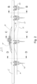
- an embodiment of an overhang rail transport system 1 for transferring carcass parts 17 from a gambrel conveyor 10 to a single carrier transport line 12 is shown.
- the gambrel conveyor and the single carrier transport line are mounted to a frame (not shown).
- the carcass parts enter a transfer zone 24 hanging one from each free end 22 (see Fig. 5a , for details) of an individual gambrel (first carrier) 15.
- the carcass parts may be one right side and one left side of a slaughter animal that has been eviscerated and halved along the spine.
- the front end of the carcass part, or other carcass parts may be removed before the gambrel transport line enters the transfer zone.
- One carcass part is hanging from an opening 18 (see Fig. 15 ) arranged in a rear leg of the slaughter animal, one of the carrier ends 22 of the gambrel 15 penetrating the opening to thereby let the carcass part hang from the gambrel.
- the animal head may still be attached to one of the right or left sides of the slaughter animal.
- the carcass parts on the gambrel conveyor 10 are transported in the direction marked 16 in Fig. 1 and pass in-between two single carrier conveyors, one marked 13', shown on the left side of Fig. 1 , and the other marked 13", shown on the right side of Fig. 1 .
- the single carrier conveyors are travelling in a direction marked 26.
- direction 16 is parallel to direction 26, and both are heading the same way.
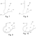
- the carriers (second carrier) 40 used on each single carrier conveyor may be a standard Euro hook or a modified Euro hook 40 (for details see Figs. 7 to 10 and 18 ).
- the single carriers are mounted to the single hook conveyors 13', 13" using a trolley arrangement 150 that allows the single carriers to at least swivel in a direction transverse to the travelling direction 26.
- the transport system for the gambrel conveyor 10 as well as the single carrier conveyors 13', 13" may be of a known type and will not be described in detail except when changes have been made to the already known types of transport system.
- the individual transport speeds of the respective conveyors 10, 13', and 13" may be set using a control system 60, which may be electrically connected to other systems (not shown) up-stream or down-stream of the transfer system 1.
- the control system may adjust the speed of the single carrier conveyor 13' to align the tip 41 of the single carrier 40 of this "left” single carrier conveyor to coincide with the location of the opening 18 arranged in the rear leg of the carcass part shown on the left side of Fig. 1 .
- the control system may adjust the speed of the single carrier conveyor 13" to align the tip 41 of the single carrier 40 of this "right” single carrier conveyor to coincide with the location of the opening 18 arranged in the rear leg of the carcass part shown on the right side of Fig. 1 .
- the speed adjustments may be in the form of a retardation of one conveyor or an acceleration of one conveyor whilst keeping the speed of another conveyor constant, or combinations of these actions.
- the overhang rail transport system 1 may have arrangements for varying the relative distance between carriers (first carrier or second carrier) by varying the horizontal and/or vertical distance between the conveyors.
- the gambrel conveyor 10 may have a first vertical bend 80, a second vertical bend 81, a third vertical bend 83 and a fourth vertical bend 84 so that the relative vertical distance between the gambrel conveyor 10 and the first carrier conveyor 13' is diminished and then extended, so that, conversely, the distance between the gambrel conveyor 10 and the second carrier conveyor 13" is extended and then diminished.
- the second carrier conveyor 13" is made to change path vertically, having a raised portion 85 to lift the second carrier to correspond to the tilting movement of the gambrel when the gambrel conveyor runs closer to the first carrier conveyor 13'.
- the raised portion 85 has a corresponding raised trolley guide 86 to stabilize the vertical position of the trolley 150 in a direction parallel to the transport direction 26 of the second carrier conveyor 13".
- the pitch or angle of the upturn corresponds to the desired change in vertical height, marked h.
- a corresponding downturn would be realized in a similar way, with a downward angling segment of conveyor.
- the gambrel conveyor 10 makes a downwards movement at a position 87 where a free end of the first carrier is aligned with one free end of the gambrel 15 at the same time a free end of the second carrier is aligned with the other free end of the gambrel. In this manner, the weight of the carcass part 17 is transferred from the gambrel free ends to the respective free end of the first and second carriers.
- the gambrel conveyor 10 further makes an upwards movement at a position 88 synchronized with the raised portion 85 of the second carrier conveyor 13".
- the gambrel conveyor stays at the raised height throughout the remainder of the transfer zone 24.
- a gambrel 15 that may be used in the transfer system 1 is shown in Fig. 5a .
- the gambrel is adapted to convey carcass parts 17, where each of the gambrels may have a free end 22 designed to extend through the opening 18 in the leg part of the carcass part causing the carcass part to be at least freely hanging.
- the gambrel 15 has a middle junction 25 that is attached to a conveying device 35 using an extension 30.
- the gambrel may be a standard type, as has been mentioned earlier.
- Figs. 7 to 10 and 18 show embodiments of single carriers 40 that may be used in the transfer system 1.
- the carrier may be comparable to a standard Euro hook and may use the same conveyor system as a Euro hook, but preferably has an elongated and substantially horizontally extended tip 41.
- the tip may be longer (e.g. Fig. 7 ) or shorter (e.g. Fig. 8 ).
- a bottom part 29 of the carrier 40 is intended for the leg part of the carcass part to be resting in, such that the weight of the carcass part is substantially hanging right under a stem 42 of the carrier.
- the stem is connected to a conveyor propulsion connection part of the carrier that is not shown in the figures.
- Figs. 9, 10 and 18 show further embodiments of single carriers 40 that may be used in the transfer system 1.
- the transition 43 from the curved carrier portion to the tip is gentler (smaller radius bend) and the tip itself may be pointing upwards at an angle of, for example, 20 to 45 degrees compared to the carriers shown in Figs. 7 and 8 .
- the carrier shown in Fig. 10 has a substantially straight transition 44 from the curved carrier portion to the tip, and the tip may be long and angled upwards.
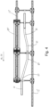
- Figs. 14 and 15 show the carrier of Fig. 7 mounted on a trolley arrangement 150 attached to the single hook conveyor 13', 13".
- the trolley may be of the type disclosed in WO2014007607 A1 .
- the carrier 40 is pivotably attached to a fork 50 via a cross-bar 51.
- the cross-bar is rotatably held in the fork via hinge points 52.
- the cross-bar rotation is about a horizontal axis.
- the fork is rotatably attached to a trolley slide 53.
- the fork rotation is about a vertical axis.
- the trolley slide is slidable along a conveyor rail 54, for example using rotatable wheels 55 or similar.
- a cam 56 having shapes corresponding to cam drives (not shown) arranged along the single hook conveyor 13', 13" may impart the rotating motion to the fork 50 at desired locations along the conveyors.
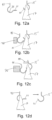
- Embodiments of tilting the carrier 40 in a direction perpendicular to the single carrier conveyor transport direction 26 are shown in Figs. 13a and 13b .
- the single carrier 40 is pivotable as has been disclosed in conjunction with Figs. 14 and 15 above.
- the carrier is pivotably attached to the fork 50 via the cross-bar 51.
- a tilting guide 49 cooperates with the stem 42 (see Figs 7 and 8 , for instance) of the carrier to angle the stem of the carrier to a desired angular position with respect to the cross-bar 51.
- the carcass may be raised (displaced in the vertical direction as shown in Fig. 13a ) simultaneously as the horizontal position of the carcass changes.
- An example when this is desirable is when a carcass has to slide down from the tip 41 to the bottom part 29 of the carrier 40 after a transfer.
- a tilting guide 49 cooperates with the stem 42 of the carrier to angle the stem of the carrier to a desired angular position with respect to the cross-bar 51.
- the carcass may be raised (displaced in the vertical direction as shown in Fig. 13b ) simultaneously as the horizontal position of the carcass changes.
- the tilting guide may be tapered to impart a gradual tilt to the carrier 40. The tilted position, in a desired angle, may be used to facilitate inserting the tip 41 into the opening of the carcass and/or removing the tip from the opening during a carcass transfer operation.
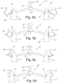
- Figs. 5a to 5h show the steps involved in de-gambreling carcass parts 17 from a gambrel 15 (first carrier) to a pair of single carriers 40 (second carrier).
- the gambrel and the single carriers have been described above for Figs. 7 to 10 and 18 .
- the gambrel conveyor 10 passes in-between two single carrier conveyors (not shown, but see description above for Figs. 1 to 4 ).
- the individual transport speeds of the respective conveyors may be set using a control system as described earlier.
- the free ends 22 of the gambrel are inserted in openings 18 (see Fig. 15 ) in the legs of the carcass parts 17 so that the carcass parts hang freely from the gambrel free ends.
- the free end of the single hook 41 is inserted in the opposite direction that the free end(s) 22 of the gambrel 15 were inserted into the openings 18.
- Fig. 5a shows an initial step where the location of the free ends 22 of the gambrel 15 are lined up with the tip 41 of the single carrier 40 on either side of the gambrel.
- the lining up may take place by adjusting the speed of either the gambrel conveyor and/or either of the single carrier conveyors.
- the control system may incorporate a vision system (not shown) for detecting the position of the individual opening 18 in the carcass part. In this case, the control system uses this position information to regulate the conveyor speeds.
- the tip 41 of each single carrier 40 is pushed into the corresponding opening 18, for example using a tapered guide 70 (as shown in Figs. 11b and 11c which will be described below).
- the weight of the carcass part 17 is held solely by the free ends 22 of the gambrel 15 at this point.
- the vertical position of the tip 41 is lower than the vertical position of the free ends.
- Figs. 5b and 5c the tip 41 of each single carrier 40 has penetrated into the respective opening 18.
- the vertical position of the free ends 22 is now lowered, with respect to the tips 41. This may be done by lowering the gambrel conveyor path or by utilizing guides 45, 46, 47 and/or 48 (as shown in Figs. 6a and 6b which will be described below).
- the guide lifts the gambrel up to a higher vertical position in preparation for the transfer operation and gradually lowers the gambrel when the tip 41 has been inserted into the opening 18.
- the guides also stabilizes the gambrel from swinging movement in any plane.
- Fig. 5d shows a step where the tip 41 is fully inserted into the opening 18, the free ends 22 of the gambrel have been lowered so that the weight of the carcass part 17 fully rests on the individual single carriers 40.
- Fig. 5e shows a step when the free ends of the gambrel have been tilted, one free end downwards (the left free end in the Figure) and the other free end upwards (the right free end in the Figure).
- the weight of the carcass part 17 still fully rests on the individual single carriers 40.
- the leftmost carcass part 17 may now be completely removed from the lower free end of the gambrel, as is shown in Fig. 5f . This may be done by utilizing a tapered guide 70 (see Figs. 11b and 11c which will be described below) to push the carcass part away from the gambrel and/or by the single carrier conveyor paths diverging outwards with respect to the gambrel conveyor.
- Fig. 5g shows a further step when the free ends of the gambrel have been tilted, one free end upwards (the left free end in the Figure, now free of its carcass part) and the other free end downwards (the right free end in the Figure, the only free end of the gambrel to carry a carcass part).
- the weight of the carcass part 17 still fully rests on the individual rightmost single carrier 40.
- the rightmost carcass part 17 may now be completely removed from the lower free end of the gambrel, as is shown in Fig. 5h . This may be done by utilizing a tapered guide 70 (see Figs. 11b and 11c which will be described below) to push the carcass part away from the gambrel and/or by the single carrier conveyor paths diverging outwards with respect to the gambrel conveyor.
- Figs. 5i to 5m show the steps involved in de-gambreling carcass parts 17 from a gambrel 15 (first carrier) to a pair of single carriers 40 (second carrier) similar to what has been described for Figs. 5a to 5h , with the difference that the free end of the single hook 41 is inserted in the same direction that the free end(s) 22 of the gambrel 15 were inserted into the openings 18 (see Fig. 15 ) in the legs of the carcass parts 17.
- the steps correspond to what has been shown for Figs. 5a to 5h , except that some steps have been omitted since they are similar to the earlier shown steps.
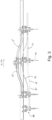
- FIGs. 11a to 11d and 12a to 12d A further embodiment is shown in Figs. 11a to 11d and 12a to 12d .
- a transfer of a carcass part 17 is made from one single carrier 15' (first carrier), of a first single carrier conveyor (similar to the two single carrier conveyors 13' and 13" as shown in Figs. 1 to 4 ), to another single carrier 40 (second carrier), of a second single carrier conveyor.
- the carriers are similar, a Euro Hook variant with a longer tip portion 41, 41'.
- Figs. 12a to 12d the carriers are one standard Euro Hook used as the first carrier, and a Euro Hook variant with a longer tip portion 41 used as the second carrier.
- Fig. 11a shows an initial step of transfer from one single carrier to another single carrier according to an embodiment of the invention.
- the location of the tips 41', 41 of the respective single carriers 15', 40 are lined up in the transport direction of the single carriers.
- the lining up may take place by adjusting the speed of either or both of the first and second single carrier conveyors.
- the control system may incorporate a vision system (not shown) for detecting the position of the individual opening 18 (see Fig. 15 ) in the carcass part. In this case, the control system uses this position information to regulate the conveyor speeds.
- the bottom part 29' of the carrier 15' in which the leg part of the carcass part is resting, has a vertical position that is higher than the vertical position of the tip of the single carrier 40 (second carrier) and the horizontal distance between the bottom part and the tip may also be considerable.
- Fig. 11b is shown how the tip 41 of the second carrier 40 is inserted into the opening 18 by the use of a guide 70.
- the vertical distance between the tip 41 and the bottom part 29' of the first carrier 15' has diminished, but the tip 41 is still below the bottom part 29'.
- the vertical movements may be done by changing the conveyor paths in a vertical direction or by utilizing guides 45, 46, 47 and/or 48 (as shown in Figs. 6a and 6b as will be described below) and/or by using a tapered guide 70, which displaces the second carrier 40 to the right in the figure as the first and second carriers travel along the transport direction. Care must be taken to compensate for the simultaneous displacement of the carriers in both vertical as well as horizontal planes. The full weight of the carcass part 17 is still resting on the first carrier 15'.
- Fig. 11c shows how the transfer of the carcass part 17 is started by pressing the carcass part from the first carrier 15' towards the second carrier 40.
- a tilt guide 49 (see Figs. 13a and 13b described earlier) may be used to angle one or both carriers perpendicularly with respect to the transport direction of each conveyor. This may alone or in combination with the tilt guide 49 be accomplished by using a carcass guide (not shown) acting on the carcass part directly. the result is the lowering of the bottom part 29' of the first carrier, and/or the raising of the tip 41 of the second carrier, so that the weight of the carcass part is gradually transferred to the second carrier. At the end of this step, the full weight of the carcass part rests on the second carrier.
- Fig. 11d is shown the step where the carcass part has been pushed to the bottom part 29 of the second carrier 40 and the first carrier 15' is completely removed from the opening 18 of the carcass part.
- Fig. 6d shows the tip 41 of the second carrier and the bottom part 29' of the first carrier being separated in the horizontal plane. The first and second conveyors may now continue on to separate goals.
- Figs. 12a to 12d the steps are identical to what has been described above for Figs. 11a to 11d , except that the first carrier is a standard Euro Hook and the second carrier is a variation of the Euro Hook having an extended tip portion 41.
- Figs. 6a and 6b show embodiments of guide arrangements that may be used in all embodiments of the transfer system according to the invention.
- Figs. 6a and 6b show guides used to stabilize, raise and/or tilt the gambrel 15.
- a first bottom guide 45 generally shaped to follow a bottom contour of the gambrel, may be used to either to stabilize the gambrel from movement in a rotating direction about the gambrel conveying device 35 and/or to raise and /or tilt the gambrel free ends 22 in a vertical direction. Each free end may be lowered or raised, but the corresponding and opposite movement is made by the other free end when tilting the gambrel.
- a similar use may be made of second bottom guides 47 shown in Fig. 6b .
- a first top guide 46 shown in Fig. 6a , may be used to stabilize the gambrel from movement in a rotating direction about the gambrel conveying device 35.
- a second top guide 48 shown in Fig. 6b , may be used to stabilize the gambrel from movement in a rotating direction about the gambrel conveying device 35.
- All of the bottom guides 45, 47 may have a profile in the travel direction of the gambrel.
- the guide profile may be lower at an entrance portion of the guides and gradually be raised to a higher profile to push the gambrel upwards by tilting the gambrel backwards and upwards towards the gambrel conveying device 35. In this way, the vertical position of the free ends 22 of the gambrel may be varied with respect to the conveying device depending upon where the gambrel is situated along the profile of the guides.
- Fig. 17 schematically illustrates how carcass parts transported in a transport direction B on a first single carrier conveyor transport device 13′′′ may be transferred in a transfer T to a second single carrier conveyor transport device 13"" moving in the same transport direction B.
- Any of the single hook to single hook transfer embodiments described earlier may be used.
- a carousel type arrangement may be used (not shown).
Landscapes
- Engineering & Computer Science (AREA)
- Life Sciences & Earth Sciences (AREA)
- Food Science & Technology (AREA)
- Mechanical Engineering (AREA)
- Wood Science & Technology (AREA)
- Zoology (AREA)
- Chain Conveyers (AREA)
- Intermediate Stations On Conveyors (AREA)
- Processing Of Meat And Fish (AREA)
Claims (15)
- Système de transport par rail en surplomb (1) pour le transport de parties de carcasse d'animal de boucherie (17) comprenant :• un premier support (15) transporté par un premier convoyeur aérien (10) dans une direction de transport et ayant une première partie d'engagement de carcasse, le premier support étant agencé pour porter sélectivement une partie de carcasse en engageant la partie de carcasse avec la première partie d'engagement de carcasse,• un second support (40) transporté par un second convoyeur aérien (12) et ayant une seconde partie d'engagement de carcasse, le second support étant agencé pour porter sélectivement une partie de carcasse en engageant la partie de carcasse avec la seconde partie d'engagement de carcasse,• un dispositif d'alignement vertical (45, 46, 47, 48) pour aligner la première partie d'engagement de carcasse et la seconde partie d'engagement de carcasse dans une direction verticale,• un dispositif d'alignement horizontal (70) pour aligner la première partie d'engagement de carcasse et la seconde partie d'engagement de carcasse dans une direction horizontale, de sorte que la première partie d'engagement de carcasse et la seconde partie d'engagement de carcasse s'engagent simultanément avec la partie de carcasse, et• un dispositif de retrait pour retirer complètement la première partie d'engagement de carcasse de l'engagement avec la partie de carcasse,
caractérisé par• un dispositif d'inclinaison (49) pour incliner la première partie d'engagement de carcasse vers le bas, de sorte que le poids de la partie de carcasse soit progressivement transféré de la première partie d'engagement de carcasse à la seconde partie d'engagement de carcasse. - Système de transport par rail en surplomb (1) selon la revendication 1, comprenant en outre :• une première section de traitement (10) comprenant de multiples premiers supports espacés (15, 15') pour acheminer des parties de carcasse (17) d'un animal de boucherie à quatre pattes, où chacun des premiers supports comprend une extrémité libre (20, 41') conçue pour s'étendre à travers une ouverture dans une partie de patte d'une des parties de carcasse, ce qui permet aux parties de carcasse d'être au moins librement suspendues,• au moins une deuxième section de traitement (12) comprenant de multiples seconds supports espacés (40, 42) où chacun des seconds supports comprend une extrémité libre (41, 43) conçue pour s'engager avec la partie de patte d'une des parties de carcasse, ce qui permet à la partie de carcasse d'être au moins librement suspendue,dans lequel le système de transport par rail en surplomb comprend en outre :• une zone de transfert (22) positionnée entre la première section de traitement et l'au moins une deuxième section de traitement,• un dispositif de commande (60) pour commander automatiquement le mouvement du premier et du second supports de sorte qu'à l'arrivée à la zone de transfert, le premier et le second supports soient synchronisés en mouvement de sorte que :• le premier support se déplaçant dans une première direction (16) en transportant la partie de carcasse à travers l'ouverture dans la partie de patte et au moins un second support vide se déplaçant dans une seconde direction (26) se rencontrent avec leurs extrémités libres respectives (20, 41) se faisant face, la zone de transfert étant conçue de sorte que pendant le mouvement du premier et du second supports :• la distance horizontale relative entre l'extrémité libre du premier support et l'extrémité libre du second support diminue jusqu'à ce que le second support s'engage avec la partie de carcasse, puis• le poids de la charge de partie de carcasse étant transféré du premier support au second support.
- Système de rail en surplomb (1) selon la revendication 2, dans lequel l'extrémité libre du second support est configurée pour s'étendre à travers l'ouverture dans la partie de patte de la partie de carcasse, ce qui permet à la partie de carcasse d'être au moins librement suspendue.
- Système de rail en surplomb (1) selon l'une des revendications 1 à 3,• dans lequel la zone de transfert est en outre conçue de sorte qu'à l'arrivée à la zone de transfert, le niveau de hauteur de l'extrémité libre du second support soit inférieur à un niveau de hauteur de l'extrémité libre du premier support de sorte que la diminution de la position relative des extrémités libres amène l'extrémité libre du second support à pénétrer dans l'ouverture au niveau de la partie de patte en dessous de l'extrémité libre du premier support.
- Système de rail en surplomb selon la revendication 4, dans lequel la zone de transfert est en outre conçue de sorte que la distance de niveau de hauteur relative entre l'extrémité libre du premier support et l'extrémité libre du second support change jusqu'à ce que le niveau de hauteur de l'extrémité libre du second support soit supérieur au niveau de hauteur du premier support provoquant le transfert de poids de la charge de partie de carcasse au second support.
- Système de rail en surplomb (1) selon l'une des revendications précédentes, comprenant en outre un dispositif de guidage (45, 46, 47, 48, 70), après le transfert de la partie de carcasse (17) au second support (40, 42), pour incliner le premier support et guider le premier support (15, 15') et/ou la partie de carcasse loin du second support, de sorte que le second support soit le seul support pour la partie de carcasse.
- Système de rail en surplomb (1) selon la revendication 6, dans lequel le dispositif de guidage comprend un élément de guidage allongé (45, 46, 47, 48, 70) agencé par rapport aux premier et second supports (15, 15' et 40, 42) de sorte que l'élément de guidage allongé interagisse avec le premier support et/ou la partie de carcasse tandis que le premier support se déplace dans la première direction (16), l'interaction forçant la première partie d'engagement de carcasse du premier support vers le bas.
- Système de rail en surplomb (1) selon la revendication 6 ou 7, dans lequel le dispositif de guidage comprend un élément de guidage allongé (45, 46, 47, 48, 70) agencé par rapport aux premier et second supports (15, 15' et 40, 42) de sorte que l'élément de guidage allongé interagisse avec le premier support et/ou la partie de carcasse tandis que le premier support se déplace dans la première direction (16), l'interaction forçant une augmentation de la distance horizontale relative entre le premier support et le second support jusqu'à une séparation complète du premier support de l'ouverture dans la partie de patte.
- Système de rail en surplomb (1) selon l'une des revendications 5 à 8, dans lequel le premier support (15, 15') est fixé en coulissement à un premier guide de rail (10') et le second support est fixé en coulissement à un second guide de rail (14), dans lequel la zone de transfert (22) est définie par l'agencement interne du premier et/ou du second guide(s) de rail provoquant le changement de la distance horizontale relative entre l'extrémité libre (20, 41') du premier support et l'extrémité libre (41, 43) du second support.
- Système de rail en surplomb selon l'une des revendications 5 à 9, dans lequel la zone de transfert (22) est en outre définie par l'agencement interne de la distance de niveau de hauteur entre le premier et/ou le second guide(s) de rail provoquant le changement de la distance de niveau de hauteur relative entre l'extrémité libre du premier support et l'extrémité libre du second support.
- Système de rail en surplomb (1) selon l'une des revendications 1 à 10, dans lequel le premier support (15, 15') comprend une structure de type jambier (15) comprenant des extrémités libres (20) au niveau de ses extrémités opposées, où chacune des extrémités opposées porte une partie de carcasse (17), dans lequel l'au moins une deuxième section de traitement (12) comprend deux deuxièmes sections de traitement, dans lequel le mouvement synchronisé se produit au niveau des extrémités opposées du jambier où les extrémités libres vides (41) des seconds supports (40) pénètrent dans l'ouverture respective au niveau des parties de patte des parties de carcasse.
- Système de rail en surplomb (1) selon l'une des revendications 1 à 11, dans lequel le premier support (15) comprend un crochet, plus spécifiquement un crochet de type Euro Hook.
- Système de rail en surplomb (1) selon l'une des revendications 1 à 10 ou 12, dans lequel le premier support (15) est identique au second support (40).
- Système de rail en surplomb (1) selon l'une des revendications précédentes, dans lequel la zone de transfert comprend en outre un guide de support tel qu'un guide conique pour interagir avec un côté arrière du premier et/ou du second type(s) de manille tandis que le second support s'engage avec la partie de carcasse et/ou tandis que la partie de carcasse est retirée de la première manille et vers la seconde manille.
- Procédé de transfert d'une partie de carcasse d'un premier support à un second support, le premier support étant transporté par un premier convoyeur aérien et ayant une première partie d'engagement de carcasse, le second support étant transporté par un second convoyeur aérien et ayant une seconde partie d'engagement de carcasse, le procédé comprenant les étapes :- de transport d'une partie de carcasse dans le premier support en engageant la partie de carcasse avec la première partie d'engagement de carcasse,- d'alignement vertical de la première partie d'engagement de carcasse et de la seconde partie d'engagement de carcasse,- d'alignement horizontal de la première partie d'engagement de carcasse et de la seconde partie d'engagement de carcasse, de sorte que la première partie d'engagement de carcasse et la seconde partie d'engagement de carcasse s'engagent simultanément avec la partie de carcasse, et- de retrait complet de la première partie d'engagement de carcasse de l'engagement avec la partie de carcasse,caractérisé par l'étape :- avant l'étape de retrait complet de la première partie d'engagement de carcasse de l'engagement avec la partie de carcasse, d'inclinaison de la première partie d'engagement de carcasse vers le bas, de sorte que le poids de la partie de carcasse soit progressivement transféré de la première partie d'engagement de carcasse à la seconde partie d'engagement de carcasse.
Applications Claiming Priority (2)
| Application Number | Priority Date | Filing Date | Title |
|---|---|---|---|
| NL2027151A NL2027151B1 (en) | 2020-12-18 | 2020-12-18 | Overhang rail transport system. |
| PCT/NL2021/050765 WO2022131914A1 (fr) | 2020-12-18 | 2021-12-15 | Système de transport par rail en porte-à-faux |
Publications (2)
| Publication Number | Publication Date |
|---|---|
| EP4262407A1 EP4262407A1 (fr) | 2023-10-25 |
| EP4262407B1 true EP4262407B1 (fr) | 2024-12-11 |
Family
ID=74592670
Family Applications (1)
| Application Number | Title | Priority Date | Filing Date |
|---|---|---|---|
| EP21830803.9A Active EP4262407B1 (fr) | 2020-12-18 | 2021-12-15 | Système et procédé de transport suspendu à un rail |
Country Status (11)
| Country | Link |
|---|---|
| US (1) | US11950602B2 (fr) |
| EP (1) | EP4262407B1 (fr) |
| JP (1) | JP7773551B2 (fr) |
| KR (1) | KR20230121784A (fr) |
| CN (1) | CN116601090B (fr) |
| DK (1) | DK4262407T3 (fr) |
| ES (1) | ES3014854T3 (fr) |
| MX (1) | MX2023004853A (fr) |
| NL (1) | NL2027151B1 (fr) |
| PL (1) | PL4262407T3 (fr) |
| WO (1) | WO2022131914A1 (fr) |
Families Citing this family (1)
| Publication number | Priority date | Publication date | Assignee | Title |
|---|---|---|---|---|
| CN118648624A (zh) * | 2024-07-18 | 2024-09-17 | 广东民昇食品有限公司 | 一种生猪输送系统 |
Family Cites Families (19)
| Publication number | Priority date | Publication date | Assignee | Title |
|---|---|---|---|---|
| DE1035005B (de) * | 1956-11-23 | 1958-07-24 | Beck & Henkel Maschb Ag | Einrichtung am Pendelhakenschlachtstand zum Umhaengen der Schweinehaelften auf den zum Abfoerdern benutzten Doppelhaken |
| US3077997A (en) * | 1961-06-22 | 1963-02-19 | Grove Res And Dev Co | Device for transferring a carcass from one conveyor to another |
| NL172295C (nl) * | 1974-09-10 | 1985-10-16 | Stork Brabant Bv | Inrichting voor het overbrengen van geslacht gevogelte van een eerste naar een tweede transportbaan. |
| GB2025883B (en) | 1978-07-20 | 1982-09-15 | Fletcher Ltd W & R | Mechanically removing gambrels from carcasses by conveying means causing relative movement between gambrel and carcass |
| AU542569B2 (en) | 1980-07-15 | 1985-02-21 | W & R W. Weddel & Company (New Zealand) Limited | Removal of gambrels from carcases |
| DE3168034D1 (en) * | 1980-10-08 | 1985-02-14 | Venturelli Rino Tecnomec | An apparatus for unhooking and transferring hung articles, in particular cuts of meat |
| CA1288559C (fr) * | 1986-12-17 | 1991-09-10 | Bernie Mcguire | Mecanisme sectionneur de jarrets |
| US4838036A (en) * | 1988-08-26 | 1989-06-13 | Knud Simonsen Industries Limited | Carcass conveyor for chilling chamber |
| JPH0318514A (ja) * | 1989-06-14 | 1991-01-28 | Bando Chem Ind Ltd | 物品の受渡し装置 |
| FR2662582B3 (fr) * | 1990-06-05 | 1992-08-28 | Couedic Madore Equipement | Dispositif de decrochage de demi-carcasses convoyees par tinets dans une chaine d'abattoir. |
| JP2000083574A (ja) * | 1998-09-08 | 2000-03-28 | Hanaki Kogyo Kk | 屠場設備における豚屠体の掛け替え方法及び装置 |
| AU2536100A (en) | 1999-02-16 | 2000-09-04 | Butina Aps | A method of deboning half pig carcasses as well as a plant for carrying out saidmethod |
| NL1012232C2 (nl) * | 1999-06-04 | 2000-12-06 | Stork Mps Bv | Werkwijze, inrichting en ophangorgaan voor het op directe of indirecte wijze positioneren van karkassen en karkasdelen van groot vee, zoals varkens en runderen. |
| DK200400603A (da) | 2004-04-16 | 2005-10-17 | K J Maskinfabriken As | Fremgangsmåde og anlæg til behandling af halvkroppe fra slagtesvin |
| NZ572040A (en) | 2008-10-15 | 2011-06-30 | Robotic Technologies Ltd | A method and device for de-gambrelling including a lifter and a leg spreader |
| DK3508064T3 (da) * | 2009-12-17 | 2021-02-01 | Marel Meat Bv | System and method for processing slaughtered animals and/or parts thereof |
| US9271506B2 (en) | 2012-07-04 | 2016-03-01 | Marel Meat Processing B.V. | System for conveying carcasses or carcass parts of quadruped slaughter animals |
| CN209573034U (zh) * | 2018-12-21 | 2019-11-05 | 松阳县宇宏家庭农场 | 一种用于家禽屠宰的输送装置 |
| NL2023063B1 (en) * | 2019-05-03 | 2020-11-30 | Marel Meat Bv | Overhang rail transport system. |
-
2020
- 2020-12-18 NL NL2027151A patent/NL2027151B1/en active
-
2021
- 2021-12-15 US US18/265,782 patent/US11950602B2/en active Active
- 2021-12-15 WO PCT/NL2021/050765 patent/WO2022131914A1/fr not_active Ceased
- 2021-12-15 KR KR1020237023020A patent/KR20230121784A/ko active Pending
- 2021-12-15 JP JP2023535436A patent/JP7773551B2/ja active Active
- 2021-12-15 CN CN202180083373.8A patent/CN116601090B/zh active Active
- 2021-12-15 MX MX2023004853A patent/MX2023004853A/es unknown
- 2021-12-15 ES ES21830803T patent/ES3014854T3/es active Active
- 2021-12-15 PL PL21830803.9T patent/PL4262407T3/pl unknown
- 2021-12-15 EP EP21830803.9A patent/EP4262407B1/fr active Active
- 2021-12-15 DK DK21830803.9T patent/DK4262407T3/da active
Also Published As
| Publication number | Publication date |
|---|---|
| ES3014854T3 (en) | 2025-04-25 |
| CA3201483A1 (fr) | 2022-06-23 |
| NL2027151B1 (en) | 2022-07-13 |
| CN116601090B (zh) | 2026-03-13 |
| PL4262407T3 (pl) | 2025-03-24 |
| US11950602B2 (en) | 2024-04-09 |
| JP7773551B2 (ja) | 2025-11-19 |
| US20240032549A1 (en) | 2024-02-01 |
| WO2022131914A1 (fr) | 2022-06-23 |
| EP4262407A1 (fr) | 2023-10-25 |
| JP2024500667A (ja) | 2024-01-10 |
| DK4262407T3 (da) | 2025-03-03 |
| KR20230121784A (ko) | 2023-08-21 |
| CN116601090A (zh) | 2023-08-15 |
| MX2023004853A (es) | 2023-05-10 |
Similar Documents
| Publication | Publication Date | Title |
|---|---|---|
| AU2020267812B2 (en) | Overhang rail transport system | |
| US5019013A (en) | On line breast halver and processor | |
| CA1164167A (fr) | Appareil pour enlever le cou d'une volaille decapitee et plumee | |
| US5947811A (en) | Apparatus for cutting up carcasses of poultry | |
| EP2996481B1 (fr) | Procédé, système et ensemble de guidage pour séparer des ensembles de viscères de volailles abattues | |
| EP4262407B1 (fr) | Système et procédé de transport suspendu à un rail | |
| CA3201483C (fr) | Système de transport par rail en porte-à-faux | |
| DK166858B1 (da) | Fremgangsmaade og anlaeg til afskinding af dyreskrog | |
| US4322872A (en) | Apparatus for breaking the neck of a fowl | |
| CN113716275B (zh) | 在高架输送机上悬挂家禽或其各部分的方法、系统及设备 | |
| GB2464600A (en) | Apparatus and method for removing carcasses from gambrels | |
| JP7067921B2 (ja) | 食肉脱骨機構および食肉脱骨装置 | |
| WO2000074491A1 (fr) | Procede et appareil pour positionner des carcasses ou des parties de carcasse d'animaux de grande taille tels que des porcs et des bovins | |
| AU622872B2 (en) | Carcass processing apparatus | |
| NZ226095A (en) | Conveyor system for stripping pelts from carcasses |
Legal Events
| Date | Code | Title | Description |
|---|---|---|---|
| STAA | Information on the status of an ep patent application or granted ep patent |
Free format text: STATUS: UNKNOWN |
|
| STAA | Information on the status of an ep patent application or granted ep patent |
Free format text: STATUS: THE INTERNATIONAL PUBLICATION HAS BEEN MADE |
|
| PUAI | Public reference made under article 153(3) epc to a published international application that has entered the european phase |
Free format text: ORIGINAL CODE: 0009012 |
|
| STAA | Information on the status of an ep patent application or granted ep patent |
Free format text: STATUS: REQUEST FOR EXAMINATION WAS MADE |
|
| 17P | Request for examination filed |
Effective date: 20230601 |
|
| AK | Designated contracting states |
Kind code of ref document: A1 Designated state(s): AL AT BE BG CH CY CZ DE DK EE ES FI FR GB GR HR HU IE IS IT LI LT LU LV MC MK MT NL NO PL PT RO RS SE SI SK SM TR |
|
| GRAP | Despatch of communication of intention to grant a patent |
Free format text: ORIGINAL CODE: EPIDOSNIGR1 |
|
| STAA | Information on the status of an ep patent application or granted ep patent |
Free format text: STATUS: GRANT OF PATENT IS INTENDED |
|
| RIC1 | Information provided on ipc code assigned before grant |
Ipc: B65G 9/00 20060101ALI20240710BHEP Ipc: B65G 47/61 20060101ALI20240710BHEP Ipc: A22B 7/00 20060101AFI20240710BHEP |
|
| INTG | Intention to grant announced |
Effective date: 20240722 |
|
| GRAS | Grant fee paid |
Free format text: ORIGINAL CODE: EPIDOSNIGR3 |
|
| GRAA | (expected) grant |
Free format text: ORIGINAL CODE: 0009210 |
|
| STAA | Information on the status of an ep patent application or granted ep patent |
Free format text: STATUS: THE PATENT HAS BEEN GRANTED |
|
| AK | Designated contracting states |
Kind code of ref document: B1 Designated state(s): AL AT BE BG CH CY CZ DE DK EE ES FI FR GB GR HR HU IE IS IT LI LT LU LV MC MK MT NL NO PL PT RO RS SE SI SK SM TR |
|
| P01 | Opt-out of the competence of the unified patent court (upc) registered |
Free format text: CASE NUMBER: APP_59319/2024 Effective date: 20241031 |
|
| REG | Reference to a national code |
Ref country code: GB Ref legal event code: FG4D |
|
| REG | Reference to a national code |
Ref country code: CH Ref legal event code: EP |
|
| REG | Reference to a national code |
Ref country code: DE Ref legal event code: R096 Ref document number: 602021023367 Country of ref document: DE |
|
| REG | Reference to a national code |
Ref country code: IE Ref legal event code: FG4D |
|
| REG | Reference to a national code |
Ref country code: NL Ref legal event code: FP |
|
| REG | Reference to a national code |
Ref country code: DK Ref legal event code: T3 Effective date: 20250227 |
|
| REG | Reference to a national code |
Ref country code: LT Ref legal event code: MG9D |
|
| PG25 | Lapsed in a contracting state [announced via postgrant information from national office to epo] |
Ref country code: HR Free format text: LAPSE BECAUSE OF FAILURE TO SUBMIT A TRANSLATION OF THE DESCRIPTION OR TO PAY THE FEE WITHIN THE PRESCRIBED TIME-LIMIT Effective date: 20241211 |
|
| PG25 | Lapsed in a contracting state [announced via postgrant information from national office to epo] |
Ref country code: FI Free format text: LAPSE BECAUSE OF FAILURE TO SUBMIT A TRANSLATION OF THE DESCRIPTION OR TO PAY THE FEE WITHIN THE PRESCRIBED TIME-LIMIT Effective date: 20241211 |
|
| PG25 | Lapsed in a contracting state [announced via postgrant information from national office to epo] |
Ref country code: BG Free format text: LAPSE BECAUSE OF FAILURE TO SUBMIT A TRANSLATION OF THE DESCRIPTION OR TO PAY THE FEE WITHIN THE PRESCRIBED TIME-LIMIT Effective date: 20241211 |
|
| PG25 | Lapsed in a contracting state [announced via postgrant information from national office to epo] |
Ref country code: NO Free format text: LAPSE BECAUSE OF FAILURE TO SUBMIT A TRANSLATION OF THE DESCRIPTION OR TO PAY THE FEE WITHIN THE PRESCRIBED TIME-LIMIT Effective date: 20250311 |
|
| PG25 | Lapsed in a contracting state [announced via postgrant information from national office to epo] |
Ref country code: LV Free format text: LAPSE BECAUSE OF FAILURE TO SUBMIT A TRANSLATION OF THE DESCRIPTION OR TO PAY THE FEE WITHIN THE PRESCRIBED TIME-LIMIT Effective date: 20241211 Ref country code: GR Free format text: LAPSE BECAUSE OF FAILURE TO SUBMIT A TRANSLATION OF THE DESCRIPTION OR TO PAY THE FEE WITHIN THE PRESCRIBED TIME-LIMIT Effective date: 20250312 |
|
| REG | Reference to a national code |
Ref country code: ES Ref legal event code: FG2A Ref document number: 3014854 Country of ref document: ES Kind code of ref document: T3 Effective date: 20250425 |
|
| PG25 | Lapsed in a contracting state [announced via postgrant information from national office to epo] |
Ref country code: IT Free format text: LAPSE BECAUSE OF NON-PAYMENT OF DUE FEES Effective date: 20241215 |
|
| PG25 | Lapsed in a contracting state [announced via postgrant information from national office to epo] |
Ref country code: RS Free format text: LAPSE BECAUSE OF FAILURE TO SUBMIT A TRANSLATION OF THE DESCRIPTION OR TO PAY THE FEE WITHIN THE PRESCRIBED TIME-LIMIT Effective date: 20250311 |
|
| REG | Reference to a national code |
Ref country code: AT Ref legal event code: MK05 Ref document number: 1749590 Country of ref document: AT Kind code of ref document: T Effective date: 20241211 |
|
| PG25 | Lapsed in a contracting state [announced via postgrant information from national office to epo] |
Ref country code: SM Free format text: LAPSE BECAUSE OF FAILURE TO SUBMIT A TRANSLATION OF THE DESCRIPTION OR TO PAY THE FEE WITHIN THE PRESCRIBED TIME-LIMIT Effective date: 20241211 |
|
| PG25 | Lapsed in a contracting state [announced via postgrant information from national office to epo] |
Ref country code: IS Free format text: LAPSE BECAUSE OF FAILURE TO SUBMIT A TRANSLATION OF THE DESCRIPTION OR TO PAY THE FEE WITHIN THE PRESCRIBED TIME-LIMIT Effective date: 20250411 |
|
| PG25 | Lapsed in a contracting state [announced via postgrant information from national office to epo] |
Ref country code: PT Free format text: LAPSE BECAUSE OF FAILURE TO SUBMIT A TRANSLATION OF THE DESCRIPTION OR TO PAY THE FEE WITHIN THE PRESCRIBED TIME-LIMIT Effective date: 20250411 |
|
| PG25 | Lapsed in a contracting state [announced via postgrant information from national office to epo] |
Ref country code: EE Free format text: LAPSE BECAUSE OF FAILURE TO SUBMIT A TRANSLATION OF THE DESCRIPTION OR TO PAY THE FEE WITHIN THE PRESCRIBED TIME-LIMIT Effective date: 20241211 |
|
| PG25 | Lapsed in a contracting state [announced via postgrant information from national office to epo] |
Ref country code: AT Free format text: LAPSE BECAUSE OF FAILURE TO SUBMIT A TRANSLATION OF THE DESCRIPTION OR TO PAY THE FEE WITHIN THE PRESCRIBED TIME-LIMIT Effective date: 20241211 |
|
| PG25 | Lapsed in a contracting state [announced via postgrant information from national office to epo] |
Ref country code: SK Free format text: LAPSE BECAUSE OF FAILURE TO SUBMIT A TRANSLATION OF THE DESCRIPTION OR TO PAY THE FEE WITHIN THE PRESCRIBED TIME-LIMIT Effective date: 20241211 |
|
| PG25 | Lapsed in a contracting state [announced via postgrant information from national office to epo] |
Ref country code: CZ Free format text: LAPSE BECAUSE OF FAILURE TO SUBMIT A TRANSLATION OF THE DESCRIPTION OR TO PAY THE FEE WITHIN THE PRESCRIBED TIME-LIMIT Effective date: 20241211 |
|
| REG | Reference to a national code |
Ref country code: CH Ref legal event code: PL |
|
| PG25 | Lapsed in a contracting state [announced via postgrant information from national office to epo] |
Ref country code: LU Free format text: LAPSE BECAUSE OF NON-PAYMENT OF DUE FEES Effective date: 20241215 |
|
| PG25 | Lapsed in a contracting state [announced via postgrant information from national office to epo] |
Ref country code: SE Free format text: LAPSE BECAUSE OF FAILURE TO SUBMIT A TRANSLATION OF THE DESCRIPTION OR TO PAY THE FEE WITHIN THE PRESCRIBED TIME-LIMIT Effective date: 20241211 |
|
| REG | Reference to a national code |
Ref country code: DE Ref legal event code: R097 Ref document number: 602021023367 Country of ref document: DE |
|
| PG25 | Lapsed in a contracting state [announced via postgrant information from national office to epo] |
Ref country code: MC Free format text: LAPSE BECAUSE OF FAILURE TO SUBMIT A TRANSLATION OF THE DESCRIPTION OR TO PAY THE FEE WITHIN THE PRESCRIBED TIME-LIMIT Effective date: 20241211 |
|
| REG | Reference to a national code |
Ref country code: BE Ref legal event code: MM Effective date: 20241231 |
|
| PG25 | Lapsed in a contracting state [announced via postgrant information from national office to epo] |
Ref country code: BE Free format text: LAPSE BECAUSE OF NON-PAYMENT OF DUE FEES Effective date: 20241231 |
|
| PLBE | No opposition filed within time limit |
Free format text: ORIGINAL CODE: 0009261 |
|
| STAA | Information on the status of an ep patent application or granted ep patent |
Free format text: STATUS: NO OPPOSITION FILED WITHIN TIME LIMIT |
|
| PG25 | Lapsed in a contracting state [announced via postgrant information from national office to epo] |
Ref country code: CH Free format text: LAPSE BECAUSE OF NON-PAYMENT OF DUE FEES Effective date: 20241231 |
|
| 26N | No opposition filed |
Effective date: 20250912 |
|
| PGFP | Annual fee paid to national office [announced via postgrant information from national office to epo] |
Ref country code: NL Payment date: 20251119 Year of fee payment: 5 |
|
| PGFP | Annual fee paid to national office [announced via postgrant information from national office to epo] |
Ref country code: DE Payment date: 20251126 Year of fee payment: 5 |
|
| PGFP | Annual fee paid to national office [announced via postgrant information from national office to epo] |
Ref country code: GB Payment date: 20251119 Year of fee payment: 5 |
|
| PG25 | Lapsed in a contracting state [announced via postgrant information from national office to epo] |
Ref country code: IT Free format text: LAPSE BECAUSE OF NON-PAYMENT OF DUE FEES Effective date: 20241215 |
|
| PGFP | Annual fee paid to national office [announced via postgrant information from national office to epo] |
Ref country code: DK Payment date: 20251119 Year of fee payment: 5 Ref country code: IT Payment date: 20251119 Year of fee payment: 5 |
|
| PGRI | Patent reinstated in contracting state [announced from national office to epo] |
Ref country code: IT Effective date: 20241231 |
|
| PGFP | Annual fee paid to national office [announced via postgrant information from national office to epo] |
Ref country code: FR Payment date: 20251120 Year of fee payment: 5 |
|
| PGFP | Annual fee paid to national office [announced via postgrant information from national office to epo] |
Ref country code: IE Payment date: 20251121 Year of fee payment: 5 |
|
| PGFP | Annual fee paid to national office [announced via postgrant information from national office to epo] |
Ref country code: PL Payment date: 20251124 Year of fee payment: 5 |
|
| PGFP | Annual fee paid to national office [announced via postgrant information from national office to epo] |
Ref country code: RO Payment date: 20251210 Year of fee payment: 5 |
|
| PGFP | Annual fee paid to national office [announced via postgrant information from national office to epo] |
Ref country code: ES Payment date: 20260102 Year of fee payment: 5 |