EP4262504B1 - Verfahrbarer reinigungsroboter - Google Patents
Verfahrbarer reinigungsroboter Download PDFInfo
- Publication number
- EP4262504B1 EP4262504B1 EP21840455.6A EP21840455A EP4262504B1 EP 4262504 B1 EP4262504 B1 EP 4262504B1 EP 21840455 A EP21840455 A EP 21840455A EP 4262504 B1 EP4262504 B1 EP 4262504B1
- Authority
- EP
- European Patent Office
- Prior art keywords
- lifting device
- push chain
- cleaning robot
- rotation element
- push
- Prior art date
- Legal status (The legal status is an assumption and is not a legal conclusion. Google has not performed a legal analysis and makes no representation as to the accuracy of the status listed.)
- Active
Links
Images





Classifications
-
- A—HUMAN NECESSITIES
- A47—FURNITURE; DOMESTIC ARTICLES OR APPLIANCES; COFFEE MILLS; SPICE MILLS; SUCTION CLEANERS IN GENERAL
- A47L—DOMESTIC WASHING OR CLEANING; SUCTION CLEANERS IN GENERAL
- A47L9/00—Details or accessories of suction cleaners, e.g. mechanical means for controlling the suction or for effecting pulsating action; Storing devices specially adapted to suction cleaners or parts thereof; Carrying-vehicles specially adapted for suction cleaners
- A47L9/009—Carrying-vehicles; Arrangements of trollies or wheels; Means for avoiding mechanical obstacles
-
- A—HUMAN NECESSITIES
- A47—FURNITURE; DOMESTIC ARTICLES OR APPLIANCES; COFFEE MILLS; SPICE MILLS; SUCTION CLEANERS IN GENERAL
- A47L—DOMESTIC WASHING OR CLEANING; SUCTION CLEANERS IN GENERAL
- A47L2201/00—Robotic cleaning machines, i.e. with automatic control of the travelling movement or the cleaning operation
- A47L2201/04—Automatic control of the travelling movement; Automatic obstacle detection
Definitions
- the invention relates to a mobile cleaning robot, in particular a stair-climbing cleaning robot.
- the KR 10 1016775 B1 A cleaning robot for stairs is known that can clean stairs independently.
- the cleaning robot has a front and a rear slider, which require the robot to be at least as high as the step to be climbed.
- a height prevents cleaning under pieces of furniture with a low clearance height.
- This cleaning robot works with a front lifting mechanism, comprising a swivel arm, and a rear lifting mechanism, comprising a vertical lifting mechanism.
- the vertical lifting mechanism is designed as a scissor lifting mechanism with two intersecting articulated levers.
- two articulated levers that can be swiveled in opposite directions are proposed.
- These solutions have the disadvantage that both the front and rear lifting mechanism require a lot of space.
- the scissor lifting system and the articulated lever system take up the entire installation space in the vertical direction. This means that the cleaning robot cannot be used to clean floor areas where there is little space in the vertical direction.
- KR-B-101407662 also discloses a cleaning robot with a lifting device.
- the present invention is based on the object of proposing a mobile cleaning robot which is particularly compact and space-saving, so that cleaning of a floor area under pieces of furniture is possible, but is also designed to travel up stairs in a stable manner and with relatively little effort for the lifting movement.
- a stair-climbing cleaning robot which comprises a housing, a first lifting device and a cleaning device.
- the first lifting device comprises a first push chain.
- a rotation element is arranged on the first push chain, wherein the first push chain is arranged to be movable on the housing for raising and/or lowering the rotation element.
- the first push chain advantageously acts as a lifting element.
- the first lifting device offers the advantage of a compact design, whereby the movable cleaning robot according to the invention can be made more compact and space-saving, particularly in comparison to a cleaning robot with a different type of lifting device.
- the cleaning robot can therefore also be used to clean floor areas with height restrictions, such as under pieces of furniture with a low clearance height.
- the first push chain can be accommodated in the housing due to its compact design.
- the first lifting device can thus be protected from potential collisions by the housing.
- the space savings achieved by using the first push chain in the first lifting device also mean that other components of the cleaning robot can also be accommodated in the housing.
- an outer surface of the housing is free of components, in particular components that are fragile and/or bulky.
- the first push chain requires less effort for a lifting movement of the cleaning robot than other lifting elements.
- the first push chain can provide the lifting force required to raise itself from the retracted position (rest position or zero position).
- the use of the first push chain in the first lifting device also has the advantage that the torque for the lifting movement is independent of the extension height.
- the movement of the first push chain is not influenced by the step height and/or the geometry of the stairs.
- the cleaning robot can therefore also travel up spiral staircases.
- the stability of the cleaning robot when climbing stairs can be improved due to the design and kinematics of the push chain.
- the term “mobile” means that the cleaning robot is movable.
- robot means that the cleaning robot can move independently (autonomously) and can carry out the cleaning of a floor area to be cleaned in an automated manner.
- the first push chain of the first lifting device acts as a lifting element. It is to be understood that for traveling up a staircase, the cleaning robot not only comprises the first lifting device with the first push chain, but also at least one further lifting device with at least one lifting element. However, in order to achieve the above-mentioned advantages in the cleaning robot, the at least one further lifting device does not have to be designed like the first lifting device. This means that it is sufficient if only one of the lifting elements is designed as a push chain.
- the cleaning robot of the present invention can have a lifting device arrangement with a plurality of lifting devices, which comprises a first lifting device, which comprises a first push chain on which a rotation element is arranged and which is arranged movably on the housing for raising and/or lowering the rotation element.
- a lifting device arrangement with a plurality of lifting devices, which comprises a first lifting device, which comprises a first push chain on which a rotation element is arranged and which is arranged movably on the housing for raising and/or lowering the rotation element.
- the rotation element is designed as a freely rotatable rotation element, in particular as a freely rotatable wheel or freely rotatable ball.
- freely rotatable means in particular that the rotation element is rotatable on a surface when the rotation element contacts the floor and the cleaning robot moves. This means that the freely rotatable rotation element is not designed to set the cleaning robot in motion.
- the freely rotatable rotation element can thus be used (only) as a support element.
- the term “rotatable” can be replaced by the term “rotatable” in the context of the invention, in particular in combination with the feature of the rotation element designed as a ball.
- the difference between a freely rotatable wheel and a freely rotatable ball is that the freely rotatable wheel can only rotate about one axis, whereas the ball can rotate about several axes.
- the rotation element is designed as a drive wheel.
- a drive wheel is designed to set the cleaning robot in motion. This means that the drive property of the drive wheel relates to the fact that the drive wheel serves as a drive element of the cleaning robot.
- an electric motor is advantageously attached to the drive wheel in such a way that the drive wheel can be rotated by the electric motor.
- the drive wheel can in particular be designed as a conventional wheel.
- a conventional wheel is a wheel which has a running surface whose axis of rotation coincides with the axis of rotation of the conventional wheel.
- the movement of the cleaning robot is preferably controlled via the rotational speeds of the drive wheels.
- the movable cleaning robot further comprises a second lifting device.
- the second lifting device comprises a first push chain on which a rotation element is arranged and which is movably arranged on the housing for raising and/or lowering the rotation element.
- the advantages described with reference to the first lifting device also relate to the second lifting device.
- the first lifting device and the second lifting device are the only lifting devices of the mobile cleaning robot.
- the mobile cleaning robot only comprises the first lifting device and the second lifting device for lifting the cleaning robot, in particular for climbing stairs.
- the rotation element of the first push chain of the first lifting device is designed as a freely rotatable rotation element, wherein the rotation element of the first push chain of the second lifting device is designed as a drive wheel.
- the rotation element of the first push chain of the first lifting device is designed as a drive wheel, wherein the rotation element of the first push chain of the second lifting device is designed as a freely rotatable rotation element.
- the first lifting device is arranged in front of the second lifting device in a forward direction of the movable cleaning robot.
- the first lifting device of the cleaning robot for/when driving up a staircase or placing the rotation element arranged on the first push chain on a step for driving up the staircase is advantageously arranged closer to the step compared to the second lifting device.
- the rotation element of the first push chain of the first lifting device is designed as a drive wheel and the rotation element of the first push chain of the second lifting device is designed as a freely rotatable rotation element, a very light structure and very good weight distribution of the cleaning robot can be achieved.
- the rotation element of the first push chain of the first lifting device is arranged in front of the rotation element of the first push chain of the second lifting device in the forward direction of the movable cleaning robot. This applies in an advantageous manner when the first push chain of the first lifting device and/or the first push chain of the second lifting device is/are in the extended state and/or retracted state.
- the forward direction is advantageously understood to be the main direction of movement of the cleaning robot, in which the cleaning robot can essentially be moved as a unit in order to travel up stairs. If the cleaning robot has a front end, a rear end, a right end and a left end, then the forward direction of the cleaning robot preferably corresponds to the direction from the rear end to the front end. If a coordinate system with a longitudinal axis, a transverse axis and a vertical axis analogous to the axes of a vehicle has been stored on the cleaning robot, in particular in a control device of the cleaning robot, the forward direction of the cleaning robot corresponds to the positive direction of the longitudinal axis.
- the forward direction is preferably horizontal.
- the forward direction particularly preferably corresponds to a direction that is perpendicular to the axis of rotation of the rotation element(s) and parallel to the surface on which the rotation element(s) can rotate.
- the movable cleaning robot preferably comprises at least one freely rotatable rotation element and/or at least one drive wheel, which is/are fixedly arranged on the housing, i.e. the at least one freely rotatable rotation element and/or the at least one drive wheel is/are not arranged to be movable relative to the housing.
- the at least one freely rotatable rotation element and/or the at least one drive wheel can carry out a rotational movement/turning movement.
- the at least one freely rotatable rotation element fixedly arranged on the housing can also be designed as a freely rotatable wheel or freely rotatable ball, like the freely rotatable rotation element arranged on a respective push chain.
- the at least one drive wheel fixedly arranged on the housing is advantageously arranged in a forward direction of the movable cleaning robot in front of the first lifting device.
- the at least one drive wheel of the cleaning robot fixedly arranged on the housing for/when driving up a staircase or placing the rotation element arranged on the first push chain on a step for driving up the staircase is advantageously arranged closer to the step compared to the first lifting device.
- the at least one drive wheel fixedly arranged on the housing is arranged in the forward direction of the movable cleaning robot in front of the rotation element of the first push chain of the first lifting device. This applies in an advantageous manner when the first push chain of the first lifting device is in the extended state and/or retracted state.
- the at least one freely rotatable rotation element fixedly arranged on the housing is advantageously arranged behind the first lifting device in the forward direction of the movable cleaning robot.
- the first lifting device of the cleaning robot for/when driving up a staircase or placing the rotation element arranged on the first push chain on a step for driving up the staircase is advantageously arranged closer to the step in comparison to the at least one freely rotatable rotation element fixedly arranged on the housing.
- the at least one freely rotatable drive wheel on the housing is arranged behind the rotation element of the first push chain of the first lifting device in the forward direction of the movable cleaning robot. This advantageously applies when the first push chain of the first lifting device is in the extended state and/or retracted state.
- the at least one freely rotatable rotation element fixedly arranged on the housing is advantageously arranged in front of the second lifting device in the forward direction of the movable cleaning robot.
- the at least one freely rotatable rotation element of the cleaning robot fixedly arranged on the housing is advantageously arranged closer to the step for/when driving up a staircase or placing the rotation element arranged on the first push chain on a step for driving up the staircase in comparison to the second lifting device.
- the at least one freely rotatable rotation element fixedly arranged on the housing is advantageously arranged in front of the rotation element of the first push chain of the second lifting device in the forward direction of the movable cleaning robot. This advantageously applies when the first push chain of the second lifting device is in the extended state and/or in the retracted state.
- a respective lifting device further comprises a second push chain.
- a corresponding rotation element ie a similar rotation element to the rotation element of the first push chain of the respective lifting device, is arranged on the second push chain.
- the first lifting device can preferably have a first push chain and a second push chain, with each push chain having a freely rotatable rotation element is arranged.
- the second lifting device can preferably have a first push chain and a second push chain, wherein a drive wheel is arranged on each push chain.
- the rotation elements of the first push chain and the second push chain of the first lifting device are preferably arranged in front of the rotation element of the first push chain of the second lifting device in the forward direction of the movable cleaning robot or, if the second lifting device also comprises a second push chain, in front of the rotation elements of the first push chain and the second push chain of the second lifting device.
- the rotation element of the first push chain of the first lifting device is preferably arranged in front of the rotation elements of the first push chain and the second push chain of the second lifting device in the forward direction of the movable cleaning robot. This advantageously applies when the first push chain of the first lifting device is in the extended state and/or in the retracted state, wherein the first push chain and the second push chain of the second lifting device are in the extended state and/or in the retracted state.
- the at least one drive wheel fixedly arranged on the housing is preferably arranged in front of the rotation elements of the first push chain and the second push chain of the first lifting device in the forward direction of the movable cleaning robot. This applies advantageously when the first push chain and the second push chain of the first lifting device are in the extended state and/or in the retracted state.
- the at least one drive wheel that can rotate freely on the housing is preferably arranged behind the rotation elements of the first push chain and the second push chain of the first lifting device in the forward direction of the movable cleaning robot. This applies advantageously when the first push chain and the second push chain of the first lifting device are in the extended state and/or in the retracted state.
- the at least one freely rotatable rotation element fixedly arranged on the housing is preferably arranged in front of the rotation elements of the first push chain and the second push chain of the second lifting device in the forward direction of the movable cleaning robot. This applies advantageously when the first push chain and the second push chain of the second lifting device are in the extended state and/or in the retracted state.
- the first push chain of a respective lifting device can be the only push chain on which another corresponding rotation element is preferably arranged, i.e. a similar rotation element to the rotation element of the first push chain of the respective lifting device already described.
- two freely rotatable rotation elements or two drive wheels can preferably be arranged on the only push chain of the respective lifting device.
- the first push chain of the first lifting device can be the only push chain of the first lifting device on which two freely rotatable rotation elements or two drive wheels are preferably arranged.
- the first push chain of the second lifting device can be the only push chain of the second lifting device on which two freely rotatable rotation elements or two drive wheels are preferably arranged.
- the first lifting device comprises a first push chain and a second push chain, as described above, wherein the second lifting device comprises a single push chain (corresponds to the previously described first push chain of the second lifting device). Accordingly, it is possible for the second lifting device to comprise a first push chain and a second push chain, as described above, wherein the first lifting device comprises a single push chain (corresponds to the previously described first push chain of the first lifting device). It is also possible for both the first lifting device and the second lifting device to each comprise a single push chain.
- the at least one freely rotatable rotation element fixedly arranged on the housing is arranged between the first lifting device and the second lifting device.
- the first lifting device is also arranged between the at least one drive wheel fixedly arranged on the housing and the at least one freely rotatable rotation element fixedly arranged on the housing.
- the at least one drive wheel fixedly arranged on the housing is on a first axis
- the rotation element/the rotation elements on the first push chain and/or the second push chain of the first lifting device is on a second axis
- the at least one freely rotatable rotation element fixedly arranged on the housing is on a third axis
- the The rotation element(s) on the first push chain and/or the second push chain of the second lifting device are arranged on a fourth axis.
- the first axis is preferably the front axis, with the fourth axis being the rear axis.
- the second axis and the fourth axis are height-adjustable axes, since the corresponding rotation elements can be raised and lowered by means of push chains.
- the second axis is located in the forward direction of the mobile cleaning robot between the first axis and the third axis, wherein the third axis is located in the forward direction of the mobile cleaning robot between the second axis and the fourth axis.
- the first push chain and the second push chain of the respective lifting device can be moved by means of a common drive device.
- the first push chain and the second push chain of the first lifting device can preferably be moved by means of a first drive device.
- the first push chain and the second push chain of the second lifting device can preferably be moved by means of a second drive device.
- the drive device of a respective lifting device preferably comprises an electric motor and two drive shafts.
- the electric motor is arranged between the first push chain and the second push chain and is connected to each push chain via a drive shaft.
- each drive shaft can be coupled to a motor shaft via a coupling device.
- a gear is advantageously provided for each push chain, which is connected to the corresponding drive shaft and is designed to convert a rotary movement of the corresponding drive shaft into a linear movement of the corresponding push chain, so that both push chains are lowered or raised together.
- the drive device can preferably comprise an electric motor and a toothed belt.
- the electric motor is arranged on the side of the housing.
- the electric motor is coupled to the first push chain by means of a first gear.
- the electric motor is coupled to the second push chain via the toothed belt and a second gear.
- a rotary movement of the electric motor can be transmitted to the second gear by means of the toothed belt, the gear being designed to convert the rotary movement of the electric motor into a linear movement of the second push chain, so that both push chains are lowered or raised together.
- the electric motor can be arranged on the housing of the cleaning robot via a lifting device housing of the respective lifting device.
- both drive devices for the first lifting device and the second lifting device are designed in the same way or are of the same type.
- one lifting device is also possible for one lifting device to be driven by one of the drive devices described above and the other lifting device to be driven by the other drive device.
- the movable cleaning robot preferably comprises a guide device for guiding a respective push chain.
- the guide device preferably comprises a telescope (telescopic device). The guide device ensures that the respective push chain is guided when moving down.
- the rotation element of the respective push chain can be arranged on the respective push chain via the guide device, in particular the telescope.
- the rotation element is advantageously arranged directly on the guide device, in particular directly on the telescope, wherein the guide device, in particular the telescope, is connected to the push chain and can thus be moved along with the push chain.
- the guide device, in particular the telescope is moved by the push chain, whereby the rotation element can be lowered and/or raised.
- the first push chain of a respective lifting device is the only push chain of the respective lifting device on which two rotation elements are arranged, as described above, it is advantageous if both rotation elements are arranged directly on the guide device, in particular directly on the telescope.
- the rotation element of a respective push chain or, in the case of a respective lifting device with a single push chain and two rotation elements arranged on it the two rotation elements are arranged directly on the respective push chain.
- the telescope is advantageously arranged on the housing, in particular perpendicular to an underside of the housing.
- the telescope is designed to move along with the push chain.
- the telescope is advantageously connected to the push chain.
- the telescope does not have an active drive (e.g. electric motor), but the telescope is set in motion by the movement of the push chain.
- the telescope it is also possible for the telescope to have an active drive, so that the telescope contributes to raising and/or lowering the rotation element arranged on the respective push chain.
- the telescope has a retracted position, which advantageously corresponds to the retracted position of the push chain, and an extended position, which advantageously corresponds to the extended position of the push chain.
- the guide device of a respective push chain comprises only one telescope.
- the guide device of a respective push chain can be designed as a telescope.
- the guide device may comprise a scissor lifting system in addition to the telescope.
- a first end of the scissor lifting system is arranged on the housing and a second end of the scissor lifting system is arranged on the respective push chain, in particular on an end of the push chain on the rotating element side.
- the scissor lifting system is not designed to raise and lower the rotating element arranged on the push chain.
- the scissor lifting system is not driven by an active drive (e.g. electric motor), but is set in motion by the movement of the push chain.
- the guide device may comprise a scissor lifting system as an alternative to the telescope.
- a first area, in particular a first end, of the scissor lifting system is advantageously arranged on the housing and a second area, in particular a second end, of the scissor lifting system is arranged on the respective push chain, in particular on an end of the push chain on the rotation element side.
- the scissor lifting system is not designed to raise and lower the rotation element arranged on the push chain.
- the scissor lifting system is not driven by an active drive (e.g. electric motor), but is set in motion by the movement of the push chain.
- the rotation element of the respective push chain can be arranged on the respective push chain via the scissor lifting system.
- the rotation element is advantageously arranged directly on the scissor lifting system, wherein the scissor lifting system is connected to the push chain and can thus be moved along with the push chain.
- the scissor lifting system is moved by the push chain, whereby the rotation element arranged directly on the scissor lifting system can be lowered and/or raised.
- the first push chain of a respective lifting device is the only push chain of the respective lifting device on which two rotation elements are arranged, as described above, it is advantageous if both rotation elements are arranged directly on the corresponding scissor lifting system.
- the rotation element of a respective push chain or, in the case of a respective lifting device with a single push chain with two rotation elements arranged on it the two rotation elements are arranged directly on the respective push chain.
- the cleaning robot comprises one guide device per push chain.
- a number of guide devices corresponds to a Number of push chains, whereby each push chain of the cleaning robot is assigned a guide device.
- a respective lifting device comprises a first push chain and a second push chain
- both the first push chain and the second push chain can be guided by connecting the first push chain and the second push chain of the respective lifting device to one another by means of a rigid connecting element.
- the rigid connecting element can be designed as a rod, for example.
- the first push chain and the second push chain of a respective lifting device can preferably be rigidly connected to one another.
- the rigid connection of the first push chain to the second push chain e.g. at the ends of the push chains on the rotating element side, can be provided in addition to or as an alternative to a previously described guide device for the first push chain or to a previously described guide device for the second push chain.
- a guide device of the first push chain can comprise a rigid connecting element and the second push chain, wherein a guide device of the second push chain can comprise the rigid connecting element and the first push chain.
- the first push chain and/or the second push chain of a respective lifting device can be stored in a magazine. This is particularly advantageous if a minimum construction height of the cleaning robot is to be achieved. This embodiment also offers the advantage that the smallest possible distance can be achieved between the first push chain and the second push chain of a respective lifting device.
- the first push chain and/or the second push chain of a respective lifting device in particular the first lifting device, can be arranged on the housing particularly preferably obliquely or parallel to a longitudinal axis of the cleaning robot.
- the longitudinal axis is parallel to a forward direction of the cleaning robot. This makes a longer chain length possible for the first push chain and/or the second push chain of the respective lifting device.
- first push chain and/or the second push chain of a respective lifting device is arranged on the housing perpendicular to the longitudinal axis of the cleaning robot.
- a respective push chain of a respective lifting device is arranged in particular so as to be displaceable on the housing.
- a respective push chain of a respective lifting device preferably each push chain of the cleaning robot, has a retracted position (first end position) and an extended position (second end position). In the retracted position, the respective push chain extends essentially parallel to a surface of the housing on which the push chain is arranged. This means in particular that the part of the push chain that is parallel to this surface of the housing is larger than the part of the push chain that is perpendicular to the surface. In the extended position, the part of the push chain that is perpendicular to the surface of the housing is longer than that in the retracted position.
- the cleaning robot comprises a control device which is configured to control the cleaning device and/or the movement of a respective push chain, in particular all push chains, and/or the driving of the drive wheels and thus the movement of the cleaning robot.
- each drive wheel of the movable cleaning robot is designed as an omnidirectional wheel.
- the cleaning robot has at least four drive wheels designed as omnidirectional wheels, the cleaning robot can move in any direction and rotate around a perpendicular axis to the surface on which the cleaning robot is moving.
- the omnidirectional wheels are designed as Mecanum wheels.
- Other types of omnidirectional wheels such as the Liddiard wheel are also possible.
- An omnidirectional wheel is a wheel that has rollers whose axes of rotation are at an angle to the axis of rotation of the omnidirectional wheel (main wheel).
- a Mecanum wheel is designed in particular in such a way that several rotatably mounted barrel-shaped rollers are attached to its circumference at an angle to the axis of the entire wheel. These rollers have no direct drive and can rotate freely around their inclined bearing axis.
- the cleaning robot can preferably be designed as a suction robot.
- the cleaning device is designed as a suction device.
- the cleaning device it is also possible for the cleaning device to have two or more, in particular different, cleaning devices, so that a large number of cleaning jobs can be ensured by means of the movable cleaning robot.
- the cleaning robot 100 comprises a housing 8 in which a first lifting device 1, a second lifting device 2, a cleaning device 5 and a control device 6 are at least partially accommodated.
- the control device 6 is set up to control the first lifting device 1, the second lifting device 2 and the cleaning device 5 accordingly.
- the cleaning device 5 is designed as a suction device.
- the cleaning robot 100 is therefore a suction robot.
- the cleaning device 5 can have another cleaning device or a variety of different cleaning devices, so that a variety of cleaning jobs can be ensured by means of the movable cleaning robot 100.
- the first lifting device 1 comprises a first push chain 11 and a second push chain 12.
- a rotation element in the form of a freely rotatable rotation element 10 is arranged on each of the push chains 11, 12.
- Each push chain 11, 12 is displaceably arranged on the housing 8 for raising and/or lowering the corresponding rotation element 20.
- the freely rotatable rotation elements 20 are each designed in particular as a ball.
- the second lifting device 2 comprises a first push chain 21 and a second push chain 22.
- a rotation element in the form of a drive wheel 20 is arranged on each of the push chains 21, 22.
- Each push chain 11, 12 is displaceably arranged on the housing 8 for raising and/or lowering the corresponding drive wheel 20.
- Raising the freely rotatable rotation elements 10 and the drive wheels 20 causes a lowering of the cleaning robot 100, wherein lowering the freely rotatable rotation elements 10 and the drive wheels 20 leads to a lifting of the cleaning robot 100 when the freely rotatable rotation elements 10 and the drive wheels 20 contact the ground.
- the first lifting device 1 and the second lifting device 2 are the only lifting devices of the movable cleaning robot 100.
- the cleaning robot 100 comprises only the first lifting device 1 and the second lifting device 2 for lifting the cleaning robot 100.
- the cleaning robot 100 comprises a freely rotatable rotation element 4 and a drive wheel 3, which are fixedly arranged on the housing 8.
- the freely rotatable rotation element 4 is designed as a freely rotatable wheel and the drive wheel 3 as a conventional wheel.
- the drive wheels 20 arranged on the push chains 21, 22 of the second lifting device 2 are also designed as conventional wheels.
- a conventional wheel is understood to be a wheel which has a running surface whose axis of rotation coincides with the axis of rotation of the entire wheel.
- the movement of the cleaning robot 100 is preferably controlled via the rotational speeds of the drive wheels 20 arranged on the push chains 21, 22 of the second lifting device 2 and of the drive wheel 3 fixedly arranged on the housing.
- the first lifting device 1 is arranged in a forward direction 600 of the cleaning robot 100 in front of the second lifting device 2.
- the forward direction is advantageously to be understood as the main direction of movement in which the cleaning robot 100 is essentially movable as a unit in order to travel up a staircase.
- the forward direction 600 corresponds to a direction from a rear end 82 to a front end 81 of the housing 8.
- a right end 83 and a left end 84 of the housing 8 are also shown.
- the forward direction 600 of the cleaning robot 100 is parallel to a longitudinal axis 105 of the cleaning robot 100.
- a transverse axis 106 of the cleaning robot 100 is drawn, which is perpendicular to the longitudinal axis 105.
- the first lifting device 1 is the front lifting device and the second lifting device 2 is the rear lifting device.
- the first lifting device 1 is the lifting device whose rotation elements, namely the freely rotatable rotation elements 10, can be placed on a step of a staircase in front of the rotation elements of the second lifting device 2, namely the drive wheels 20.
- the drive wheel 3, which is fixedly arranged on the housing 8, is arranged in front of the first lifting device 1 in the forward direction 600 of the cleaning robot 100. Furthermore, the freely rotatable rotation element 4, which is fixedly arranged on the housing 8, is arranged behind the first lifting device 1 and in front of the second lifting device 2 in the forward direction 600 of the cleaning robot 100.
- the freely rotatable rotation element 4 fixedly arranged on the housing 8 is positioned between the first lifting device 1 and the second lifting device 2. Furthermore, the first lifting device 1 is positioned between the drive wheel 3 fixedly arranged on the housing 8 and the freely rotatable rotation element 4 fixedly arranged on the housing 8.
- the drive wheel 3 fixedly arranged on the housing 8 is on a first axis 101
- the freely rotatable rotation elements 10 arranged on the push chains 11, 12 of the first lifting device 1 are on a second axis 102
- the freely rotatable rotation element 4 fixedly arranged on the housing 8 is on a second axis 103.
- rotatable rotation element 4 is arranged on a third axis 103 and the drive wheels 20 arranged on the push chains 21, 22 of the second lifting device 2 are arranged on a fourth axis 104.
- the first axis 101 is the front axis, with the fourth axis 104 being the rear axis.
- the second axis 102 and the fourth axis 104 are height-adjustable axes.
- first push chain 11 and the second push chain 12 of the first lifting device 1 as well as the first push chain 21 and the second push chain 22 of the second lifting device 2 are arranged on the housing 8 perpendicular to the longitudinal axis 105 of the cleaning robot 100.
- the push chains 11, 12, 21, 22 are arranged on the housing 8 such that their longitudinal axes are parallel to the transverse axis 106 of the cleaning robot 100.
- a distance 110 between the front end 81 of the housing 8 and the second lifting device 2, in particular the second axis 104, in the longitudinal axis 105 of the cleaning robot 100 is advantageously less than or equal to a stair tread or a step width of a staircase.
- the cleaning robot 100 comprises a guide device 7 for each push chain 11, 12, 21, 22.
- all guide devices 7 are preferably designed as telescopes 70.
- the telescopes 70 are each attached to the housing 8 at one end and connected to the rotating element end of the corresponding push chain at the other end.
- the telescopes 70 have no active drive.
- the telescopes are thus moved by the push chains 11, 12, 21, 22 during a movement of the push chains 11, 12, 21, 22.
- the telescopes 70 and the push chains 11, 12, 21, 22 are in an extended position.
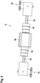
- the cleaning robot 100 comprises a drive device 9 for each lifting device 1, 2.
- the drive device 9 is in Figure 4 shown.
- the drive device 9 for the first lifting device 1 is described below.
- the drive device for the second lifting device 2 can be designed in the same way.
- the drive device 9 comprises an electric motor 90 and two drive shafts 93.
- the electric motor 90 is arranged between the first push chain 11 and the second push chain 12 of the first lifting device 1.
- the electric motor 90 is connected to the first push chain 11 via a drive shaft 93 and to the second push chain 12 via a further drive shaft 93.
- each drive shaft 93 can be coupled to a motor shaft of the electric motor 90 via a coupling device 94.
- a first gear 91 is provided, which is connected to the drive shaft 93 and is designed to convert a rotary movement of the drive shaft 93 into a linear movement of the first push chain 11.
- a second gear 92 is provided, which is connected to the further drive shaft 93 and is designed to convert a rotary movement of the further drive shaft 93 into a linear movement of the second push chain 12.
- the first gear 91 and the second gear 92 are arranged such that the first push chain 11 and the second push chain 12 are lowered or raised together.
- the first gear 91 and the second gear 92 also each have a push chain-side part.
- the motor-side parts of the first gear 91 and the second gear 92 can each have an engagement element, e.g. a gear.
- the push chain-side part of the first gear 91 can comprise an engagement region of the first push chain 11 and the push chain-side part of the second gear 92 can comprise an engagement region of the second push chain 12, the engagement regions being in engagement with the engagement elements.
- FIG 5 1 shows a drive device 9 in a cleaning robot 100 according to a second embodiment of the present invention.
- the drive device 9 is described with reference to the first lifting device 1.
- the second lifting device 2 can also be driven by a drive device of the same design.
- the drive device 9 comprises an electric motor 90 and a toothed belt 95.
- the electric motor 90 is arranged laterally on the housing 8.
- the electric motor 90 is coupled to the first push chain 11 of the first lifting device 1 by means of a first gear 91.
- the electric motor 90 is coupled to the second push chain 12 of the first lifting device 1 by means of the toothed belt 95 and a second gear 92.
- a rotary movement of the electric motor 90 can be transmitted to the second gear 92.
- the second gear 92 is designed to convert the rotary movement of the electric motor 90 into a linear movement of the second push chain 12, so that both push chains 11, 12 of the first Lifting device 12 can be lowered or raised together.
- first gear 91 and the second gear 92 are shown.
- the first gear 91 and the second gear 92 also each have a push chain-side part.
- the motor-side parts of the first gear 91 and the second gear 92 can each have an engagement element, e.g. a gear.
- the push chain-side part of the first gear 91 can comprise an engagement region of the first push chain 11 and the push chain-side part of the second gear 92 can comprise an engagement region of the second push chain 12, the engagement regions being in engagement with the engagement elements.
- FIG. 6 a portion of a cleaning robot 100 according to a third embodiment of the present invention is shown.
- first push chain 21 and the second push chain 22, in particular the rotation element-side ends of the first push chain 21 and the second push chain 22, of the second lifting device 2 are connected to one another by means of a rigid connecting element 71.
- the rigid connecting element 71 can be designed as a rod, for example.
- the first push chain 21 and the second push chain 22 of the second lifting device 2 are rigidly connected to one another.
- the rigid connection of the first push chain 21 to the second push chain 22 can be provided in addition to or as an alternative to the guide device 7 in the cleaning robot 100 according to the first exemplary embodiment.
- the first push chain 11 and the second push chain 12 of the first lifting device 1 can be connected to one another by means of a further rigid connecting element 71.
- the remaining structure of the cleaning robot 100 according to the third embodiment preferably corresponds to that of the cleaning robot 100 according to the first embodiment.
- FIG. 7 a cleaning robot 100 according to a fourth embodiment of the invention is shown.
- the cleaning robot 100 according to the fourth embodiment differs from the cleaning robot 100 according to the first embodiment in that in the cleaning robot 100 according to the fourth embodiment the push chains 11, 12 of the first lifting device 1 are arranged parallel to the forward direction 600. This means that the push chains 11, 12 of the first lifting device 1 are arranged parallel to the longitudinal axis 105 of the cleaning robot 100.
- the longitudinal axes of the push chains 11, 12 of the first lifting device 1 are each perpendicular to the first axis 101. However, it is also possible for the push chains 11, 12 to be arranged at an angle to the first axis 101.
- This arrangement of the push chains 11, 12 can be of great advantage if a width of the housing 8 at the location of the first axis 101 is smaller than the stroke of the push chains 11, 12. This allows a longer chain length for the push chains 11, 12 of the first lifting device 1 without the push chains 11, 12 having to be folded over. This means that a magazine into which the push chains 11, 12 of the first lifting device 1 could be folded over is not required.
- a further difference between the cleaning robots 100 of the first embodiment and the fourth embodiment is that in the fourth embodiment the drive device 9 for driving the push chains 11, 12 of the first lifting device 1 comprises, in addition to the electric motor 90, only one drive shaft 93, only one coupling device 94, via which the drive shaft 93 is connected to the electric motor 90, and only the first gear 91.
- the first gear 91 is designed such that both push chains 11, 12 of the first lifting device 1 can be moved together in the same direction. This means in particular that the Figure 4 shown first gear 91 is adapted accordingly so that its motor-side part has two engagement elements.
- the drive device 9 for driving the push chains 21, 22 of the second lifting device 2 can be like the drive device 9 of Figure 4 or 5 be trained.
- push chains 11, 12 of the first lifting device in particular their rotation element-side ends, can be rigidly connected to one another alternatively or in addition to the guide device 7.
- FIG 8 a cleaning robot 100 according to a fifth embodiment of the invention is shown.
- the structure of the cleaning robot 100 according to the fifth embodiment basically corresponds to that of the cleaning robot 100 according to the first embodiment.
- the cleaning robots 100 of these embodiments differ from one another in that two drive wheels 3 are fixedly arranged on the housing 8 on the first axis 101 of the cleaning robot 100 according to the fifth embodiment.
- a further difference is that the drive wheels 3 on the first axle 101 and the drive wheels 20 arranged on the push chains 21, 22 of the second lifting device 2 are designed as omnidirectional wheels, in particular as Mecanum wheels, and not as conventional wheels.
- a distance 111 between the drive wheels 3 in a direction parallel to the transverse axis 106 of the cleaning robot 100 is equal to a distance 112 between the drive wheels 20 in the direction parallel to the transverse axis 106 of the cleaning robot 100.
- the cleaning robot 100 must approach the stairs 500.
- the push chains 11, 12 of the first lifting device 1 and the push chains 21, 22 of the second lifting device 2 are lowered.
- the drive devices 9 are controlled by means of the control device 6 to move the push chains 11, 12 and 21 and 22 from their respective retracted position to their respective extended position.
- the cleaning robot 100 In the retracted position of the lifting devices 1, 2, the cleaning robot 100 is in its folded position.
- the lowering of the push chains 11, 12, 21, 22 results in the cleaning robot 100 being raised so that finally the freely rotatable rotation element 4 fixedly arranged on the housing 8 and the drive wheel 3 fixedly arranged on the housing 8 are at a height that is greater than or equal to the height of the first stage 501.
- This state of the cleaning robot 100 is shown in Figure 10 shown.
- Figure 9 shows a state of the cleaning robot 100 in which the push chains 11, 12, 21, 22 are partially extended.
- the cleaning robot 100 then moves forwards so that the drive wheel 3 fixed to the housing 8 is positioned above the first step 501 of the stairs 500 and contacts the surface of the first step 501.
- the drive wheels 20 arranged on the push chains 21, 22 of the second lifting device 2 are driven.
- the push chains 11, 12 of the first lifting device 1 are raised, i.e. brought from their respective extended position into their respective retracted position. This state is shown in Figure 11
- all drive wheels 3, 10 of the cleaning robot 100 are driven so that the cleaning robot 100 moves forward. This state is shown in Figure 12 shown.
- the cleaning robot 100 can now by driving the drive wheels 3 fixed to the housing 8, the cleaning robot 100 can be moved forward until the entire cleaning robot 100 is on the first step 501. By suitably driving the drive wheels 3, 20, the cleaning robot 100 can move freely on the first step 501 until the first step 501 is cleaned.
- the cleaning process of the first step 501 is completed, the previously described operating mode of the cleaning robot 100 is repeated so that the cleaning robot 100 is finally positioned on the second step 502.
- the reverse procedure can be followed.
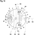
- FIG. 13 a cleaning robot 100 according to a sixth embodiment of the invention is shown.
- the first push chain 21 of the second lifting device 2 is the only push chain of the second lifting device 2. This is advantageously arranged parallel to the forward direction 600 and the longitudinal axis 105 of the cleaning robot 100.
- the cleaning robot 100 can have a drive device 9 with an electric motor 90, which in particular faces a rotation element-side end of the only push chain 21 in the longitudinal axis 105 of the cleaning robot 100.
- a drive device 9 is provided in the cleaning robot 100, which, like the drive devices 9 from Figure 4 or Figure 5 can be trained.
- a further difference between the cleaning robot 100 according to the first embodiment and the sixth embodiment is that two freely rotatable rotation elements 10 are arranged on the single shoe chain 21 of the second lifting device 2.
- Both freely rotatable rotation elements 10 are advantageously arranged on the single push chain 21 of the second lifting device 2 via a guide device 7, in particular a telescope 70.
- the freely rotatable rotation elements 10 are arranged directly on the guide device 7, in particular the telescope 70, with the single push chain 21 of the second lifting device 2 being directly connected to the guide device 7, in particular the telescope 70.
- Moving the single push chain 21 of the second lifting device 2 causes the guide device 7 to move and thus the lowering and raising of the freely rotatable rotation elements 10.
- the guide device 7 serves to guide the single push chain 21 of the second lifting device 2.
- the telescope 70 is extended by extending the single push chain 21 of the second lifting device 2. This allows the freely rotatable rotation elements 10 to be lowered. The retraction of the single push chain 21 of the second lifting device 2 leads to a Retraction of the telescope 70, whereby the freely rotatable rotation elements 10 can be lifted.
- the cleaning robot 100 according to the sixth embodiment further differs from the cleaning robot 100 according to the first embodiment in that a drive wheel 20 is arranged on the first push chain 11 and the second push chain 12 of the first lifting device 1 in the cleaning robot 100 according to the sixth embodiment instead of a freely rotatable rotation element.
- the arrangement of the lifting devices 1, 2 in relation to one another, to the freely rotatable rotation element 4 fixedly arranged on the housing 8 and to the drive wheel 3 fixedly arranged on the housing 8 is the same as that in the cleaning robot 100 according to the first exemplary embodiment.
- the first lifting device 1 is arranged in front of the second lifting device 2 in a forward direction 600 of the cleaning robot 100.
- the first lifting device 1 is the lifting device whose rotation elements, namely the drive wheels 20, can be placed on a step of a staircase in front of the rotation elements of the second lifting device 2, namely the freely rotatable rotation elements 10.
- the drive wheel 3 fixedly arranged on the housing 8 is arranged in front of the first lifting device 1 in the forward direction 600 of the cleaning robot 100. Furthermore, the freely rotatable rotation element 4 fixedly arranged on the housing 8 is arranged behind the first lifting device 1 and in front of the second lifting device 2 in the forward direction 600 of the cleaning robot 100. The freely rotatable rotation element 4 fixedly arranged on the housing 8 is thus positioned between the first lifting device 1 and the second lifting device 2. Furthermore, the first lifting device 1 is positioned between the drive wheel 3 fixedly arranged on the housing 8 and the freely rotatable rotation element 4 fixedly arranged on the housing 8.
- the drive wheel 3 fixedly arranged on the housing 8 is arranged on the first axis 101
- the drive wheels 20 arranged on the push chains 11, 12 of the first lifting device 1 are arranged on the second axis 102
- the freely rotatable rotation element 4 fixedly arranged on the housing 8 is arranged on the third axis 103
- the freely rotatable rotation elements 10 arranged on the single push chain 21 of the second lifting device 2 are arranged on the fourth axis 104.
- the first axis 101 is the front axis, with the fourth axis 104 being the rear axis.
- the second axis 102 and the fourth axis 104 are height-adjustable axes.
- the second axis 102 is located in the forward direction 600 between the first axis 101 and the third axis 103, wherein the third axis 103 is in the forward direction 600 is arranged between the second axis 102 and the fourth axis 104.
- the drive wheels 20 of the push chains 11, 12 of the first lifting device 1 are arranged in the forward direction 600 of the movable cleaning robot 100 in front of the freely rotatable rotation elements 10 of the single push chain 21 of the second lifting device 2. This applies in the extended and retracted state of the push chains 11, 12, 21 of the lifting devices 1, 2.
- the drive wheel 3 fixedly arranged on the housing 8 is arranged in the extended and retracted state of the push chains 11, 12 of the first lifting device 1 in the forward direction 600 in front of the drive wheels 20 of the push chains 11, 12 of the first lifting device 1.
- the freely rotatable drive wheel 4 on the housing 8 is arranged in the extended state and retracted state of the push chains 11, 12 of the first lifting device 1 in the forward direction 600 behind the drive wheels 20 of the push chains 11, 12 of the first lifting device 1.
- the freely rotatable rotation element 4 fixedly arranged on the housing 8 is arranged in the extended state and/or in the retracted state of the single push chain 21 of the second lifting device 2 in the forward direction 600 in front of the freely rotatable rotation elements 10 of the single push chain 21 of the second lifting device 2.
- the cleaning robot 100 must approach the stairs 500.
- the push chains 11, 12 of the first lifting device 1 and the only push chain 21 of the second lifting device 2 are lowered.
- the drive devices 9 are controlled by the control device 6 to move the push chains 11, 12 and 21 from their respective retracted position to their respective extended position.
- the cleaning robot 100 In the retracted position of the lifting devices 1, 2, the cleaning robot 100 is in its folded position, ie in the position of its minimum device height.
- the cleaning robot 100 then moves forwards so that the drive wheel 3 fixed to the housing 8 is positioned above the first step 501 of the stairs 500 and contacts the surface of the first step 501.
- the drive wheels 20 arranged on the push chains 11, 12 of the first lifting device 1 are driven.
- the push chains 11, 12 of the first lifting device 1 are raised, i.e. brought from their respective extended position into their respective retracted position. This state is shown in Figure 16 shown.
- the drive wheel 3 of the cleaning robot 100 which is fixedly arranged on the housing 8, is driven so that the cleaning robot 100 moves forward until the drive wheels 20 are positioned above the first step 501 of the stairs 500 and contact the surface of the first step 501.
- both the drive wheels 20 of the push chains 11, 12 of the first lifting device 1 and the drive wheel 3 fixedly arranged on the housing 8 can be driven until the freely rotatable rotation element 4 fixedly arranged on the housing 8 is positioned above the first step 501 of the stairs 500 and contact the surface of the first step 501.
- the single push chain 21 of the second lifting device 2 is first raised. This state is shown in Figure 17 shown.
- the cleaning robot 100 can now be moved forward by driving the drive wheel 3 fixed to the housing 8 and the drive wheels 20 of the push chains 11, 12 of the first lifting device 1 until the complete cleaning robot 100 is on the first step 501.
- the cleaning robot 100 can move freely on the first step 501 until the first step 501 is cleaned.
- the previously described operating mode of the cleaning robot 100 is repeated so that the cleaning robot 100 is finally positioned on the second step 502.
- the reverse procedure can be followed.
- Figure 18 relates to a cleaning robot 100 according to a seventh embodiment of the invention. In Figure 18 only one area of the cleaning robot 100 is shown.
- the cleaning robot 100 according to the seventh embodiment differs from that according to the sixth embodiment in that the guide device 7 for guiding the single push chain 21 of the second lifting device 2 according to the seventh embodiment does not have a telescope, but a scissor lifting system 72.
- a first region 721, in particular a first end, of the scissor lifting system 72 is attached to the housing 8 and a second area 722 of the scissor lifting system 72 are arranged on the single push chain 21.
- the freely rotatable rotation elements 10 are arranged on the single push chain 21 via the scissor lifting system 72. In other words, the freely rotatable rotation elements 10 are arranged directly on the scissor lifting system 72.
- the scissor lifting system 72 is not designed to raise and lower the freely rotatable rotation elements 10 arranged on the single push chain 21 (by itself).
- the scissor lifting system 72 is not driven by an active drive (e.g. electric motor), but is set in motion by the movement of the push chain 21. This means that the scissor lifting system 72 is moved by the push chain 21, whereby the freely rotatable rotation elements 10 can be lowered and/or raised.
- the push chain 21 is guided during its movement, in particular during its extension.
- the first lifting device 1 has two push chains 11, 12.
- the first lifting device 1 also comprises a single push chain 11 on which two drive wheels 20 are arranged, in particular via the respective guide device 7.
Landscapes
- Engineering & Computer Science (AREA)
- Mechanical Engineering (AREA)
- Manipulator (AREA)
Description
- Die Erfindung betrifft einen verfahrbaren Reinigungsroboter, insbesondere einen treppenfahrenden Reinigungsroboter.
- Der Stand der Technik kennt derartige Reinigungsroboter.
- Beispielsweise ist aus der
KR 10 1016775 B1 - Aus der
DE 10 2016 111819 A1 ist ein weiterer Reinigungsroboter für Treppenstufen bekannt. Dieser Reinigungsroboter arbeitet mit einem vorderen Hebewerk, umfassend einen Schwenkarm, und einem hinteren Hebewerk, umfassend ein Vertikalhubwerk. Das Vertikalhubwerk wird als Scherenhubwerk mit zwei sich kreuzenden Gelenkhebeln ausgeführt. Alternativ dazu werden zwei gegensinnig schwenkbare Gelenkhebel vorgeschlagen. Diese Lösungen weisen den Nachteil auf, dass sowohl das vordere als auch das hintere Hebewerk viel Platz erfordern. Insbesondere beanspruchen das Scherenhubsystem und das Gelenkhebelsystem den kompletten Bauraum in Vertikalrichtung. Somit kann der Reinigungsroboter nicht zum Reinigen von Bodenflächen benutzt werden, wo wenig Platz in der Vertikalrichtung vorhanden ist. Ferner soll mit der Schwenkbewegung des Schwenkarmes, mit der der Roboter auf die nächste Stufe gehoben werden soll, der Schwerpunkt des Roboters verlagert werden, was aufgrund der Hebellänge einen unverhältnismäßig hohen Kraftaufwand erforderlich macht. Bezüglich des hinteren Hebewerks ist sowohl bei der Lösung mit dem Scherenhubwerk als auch bei der Lösung mit den Gelenkhebeln das Problem, dass das Bewegen aus der Ruhelage heraus einen sehr hohen Kraftaufwand erfordert. Ferner kann das Bewegen des Reinigungsroboters beim Befahren einer Treppe wacklig sein.KR-B-101407662 - Insbesondere liegt der vorliegenden Erfindung die Aufgabe zugrunde, einen verfahrbaren Reinigungsroboter vorzuschlagen, der besonders kompakt und platzsparend ist, so dass eine Reinigung einer Bodenfläche unter Möbelstücken möglich ist, aber auch eingerichtet ist, eine Treppe in stabiler Weise und mit relativ niedrigem Kraftaufwand für die Hubbewegung zu befahren.
- Die Lösung dieser Aufgabe erfolgt durch die Merkmalskombination des unabhängigen Anspruchs. Die Unteransprüche haben vorteilhafte Weiterbildungen und Aspekte der Erfindung zum Inhalt.
- Vorgeschlagen wird ein treppenfahrender Reinigungsroboter, der ein Gehäuse, eine erste Hubvorrichtung und eine Reinigungsvorrichtung umfasst. Die erste Hubvorrichtung umfasst eine erste Schubkette. An der ersten Schubkette ist ein Rotationselement angeordnet, wobei die erste Schubkette zum Heben und/oder Senken des Rotationselements am Gehäuse bewegbar angeordnet ist. Die erste Schubkette wirkt dabei in vorteilhafter Weise als ein Hubelement.
- Die erste Hubvorrichtung bietet den Vorteil eines kompakten Aufbaus, wodurch der erfindungsgemäße verfahrbare Reinigungsroboter insbesondere im Vergleich zu einem Reinigungsroboter mit einer verschiedenartigen Hubvorrichtung kompakter und platzsparender ausgebildet werden kann. Dies wird dadurch ermöglicht, dass die erste Schubkette der ersten Hubvorrichtung im eingefahrenen Zustand wenig Speicherplatz benötigt, wodurch der Reinigungsroboter insgesamt mit einer geringen Bauhöhe gebaut werden kann. Somit kann der Reinigungsroboter auch zum Reinigen von Bodenflächen mit Höhenbeschränkungen, wie z.B. unter Möbelstücken mit niedriger Unterfahrhöhe, verwendet werden. Weiterhin kann die erste Schubkette aufgrund ihres kompakten Aufbaus im Gehäuse untergebracht werden. Somit kann die erste Hubvorrichtung vor potentiellen Kollisionen durch das Gehäuse geschützt werden. Die erreichte Platzersparnis durch die Verwendung der ersten Schubkette in der ersten Hubvorrichtung hat ferner zur Folge, dass auch weitere Komponenten des Reinigungsroboters im Gehäuse untergebracht werden können. Somit ist es möglich, dass eine Außenfläche des Gehäuses frei von Komponenten ist, insbesondere von Komponenten, die zerbrechlich und/oder sperrig sind. Außerdem erfordert die erste Schubkette einen geringeren Kraftaufwand für eine Hubbewegung des Reinigungsroboters als andere Hubelemente. Insbesondere kann die erste Schubkette die erforderliche Hubkraft zur Verfügung stellen, um sich aus der eingefahrenen Position (Ruhelage oder Nulllage) aufzurichten. Die Verwendung der ersten Schubkette in der ersten Hubvorrichtung hat ferner den Vorteil, dass das Drehmoment für die Hubbewegung unabhängig von einer Ausfahrhöhe ist. Dadurch wird die Bewegung der ersten Schubkette nicht von der Stufenhöhe und/oder der Treppengeometrie beeinflusst. Der Reinigungsroboter kann somit auch Wendeltreppen befahren. Zudem kann die Stabilität des Reinigungsroboters beim Befahren einer Treppe aufgrund des Aufbaus und der Kinematik der Schubkette verbessert werden.
- Es sei angemerkt, dass der Begriff "verfahrbar" bedeutet, dass der Reinigungsroboter bewegbar ist. Ferner bedeutet der Begriff "Roboter", dass der Reinigungsroboter sich selbständig (autonom) bewegen und die Reinigung einer zu reinigenden Bodenfläche automatisiert durchführen kann.
- Wie schon beschrieben wirkt die erste Schubkette der ersten Hubvorrichtung als Hubelement. Es ist zu verstehen, dass zum Befahren einer Treppe der Reinigungsroboter nicht nur die erste Hubvorrichtung mit der ersten Schubkette, sondern auch zumindest eine weitere Hubvorrichtung mit mindestens einem Hubelement umfasst. Allerdings muss zum Auftreten der oben genannten Vorteile beim Reinigungsroboter die zumindest eine weitere Hubvorrichtung nicht wie die erste Hubvorrichtung ausgebildet sein. Das heißt, dass es ausreichend ist, wenn nur eines der Hubelemente als Schubkette ausgebildet ist. Mit anderen Worten kann gesagt werden, dass der Reinigungsroboter der vorliegenden Erfindung eine Hubvorrichtungsanordnung mit einer Mehrzahl von Hubvorrichtungen aufweisen kann, die eine erste Hubvorrichtung umfasst, welche eine erste Schubkette umfasst, an der ein Rotationselement angeordnet ist und die zum Heben und/oder Senken des Rotationselements am Gehäuse bewegbar angeordnet ist. Der Begriff "Mehrzahl von Hubvorrichtungen" bedeutet hier, dass die Hubvorrichtungsanordnung mindestens zwei Hubvorrichtungen umfasst.
- Nach einer bevorzugten Ausgestaltung der Erfindung ist das Rotationselement als frei rotierbares Rotationselement, insbesondere als frei rotierbares Rad oder frei rotierbare Kugel, ausgebildet. "Frei rotierbar" bedeutet im Rahmen der Erfindung insbesondere, dass das Rotationselement auf einer Fläche rotierbar ist, wenn das Rotationselement den Boden kontaktiert und sich der Reinigungsroboter bewegt. Das heißt, dass das frei rotierbare Rotationselement nicht eingerichtet ist, den Reinigungsroboter in Bewegung zu bringen. Somit kann das frei rotierbare Rotationselement (nur) als Stützelement benutzt werden. Der Begriff "rotierbar" kann im Rahmen der Erfindung, insbesondere in Kombination mit dem Merkmal des als Kugel ausgebildeten Rotationselementes, durch den Begriff "drehbar" ersetzt werden. Der Unterschied zwischen einem frei rotierbaren Rad und einer frei rotierbaren Kugel besteht darin, dass das frei rotierbare Rad nur um eine Achse rotierbar ist, wohingegen die Kugel um mehrere beliebige Achsen rotierbar ist.
- Nach einer alternativen vorteilhaften Ausgestaltung der Erfindung ist das Rotationselement als Antriebsrad ausgebildet. Im Rahmen der Erfindung ist ein Antriebsrad eingerichtet, den Reinigungsroboter in Bewegung zu bringen. Das heißt, dass die Antriebseigenschaft des Antriebsrades sich darauf bezieht, dass das Antriebsrad als Antriebselement des Reinigungsroboters dient. Dazu ist am Antriebsrad in vorteilhafter Weise ein elektrischer Motor derart angebracht, dass das Antriebsrad durch den elektrischen Motor rotiert werden kann.
- Das Antriebsrad kann insbesondere als ein konventionelles Rad ausgebildet sein. Ein konventionelles Rad ist ein Rad, welches eine Laufläche aufweist, deren Drehachse mit der Drehachse des konventionellen Rades übereinstimmt.
- Die Bewegung des Reinigungsroboters wird bevorzugt über die Drehgeschwindigkeiten der Antriebsräder gesteuert.
- Bevorzugt umfasst der verfahrbare Reinigungsroboter ferner eine zweite Hubvorrichtung. Die zweite Hubvorrichtung umfasst eine erste Schubkette, an der ein Rotationselement angeordnet ist und die zum Heben und/oder Senken des Rotationselements am Gehäuse bewegbar angeordnet ist. Die mit Bezug auf die erste Hubvorrichtung beschriebenen Vorteile betreffen auch die zweite Hubvorrichtung.
- Besonders bevorzugt sind die erste Hubvorrichtung und die zweite Hubvorrichtung die einzigen Hubvorrichtungen des verfahrbaren Reinigungsroboters. Mit anderen Worten umfasst der verfahrbare Reinigungsroboter nur die erste Hubvorrichtung und die zweite Hubvorrichtung zum Heben des Reinigungsroboters, insbesondere zum Befahren einer Treppe.
- Vorzugsweise ist das Rotationselement der ersten Schubkette der ersten Hubvorrichtung als frei rotierbares Rotationselement ausgebildet, wobei das Rotationselement der ersten Schubkette der zweiten Hubvorrichtung als Antriebsrad ausgebildet ist.
- Nach einer alternativen vorteilhaften Ausgestaltung der Erfindung ist das Rotationselement der ersten Schubkette der ersten Hubvorrichtung als Antriebsrad ausgebildet, wobei das Rotationselement der ersten Schubkette der zweiten Hubvorrichtung als frei rotierbares Rotationselement ausgebildet ist.
- Vorzugsweise ist die erste Hubvorrichtung in einer Vorwärtsrichtung des verfahrbaren Reinigungsroboters vor der zweiten Hubvorrichtung angeordnet. Mit anderen Worten ist die erste Hubvorrichtung des Reinigungsroboters zum/beim Hochfahren einer Treppe bzw. Aufsetzen des an der ersten Schubkette angeordneten Rotationselementes auf eine Treppenstufe zum Hochfahren der Treppe im Vergleich zur zweiten Hubvorrichtung in vorteilhafter Weise näher zur Treppenstufe angeordnet. Insbesondere wenn das Rotationselement der ersten Schubkette der ersten Hubvorrichtung als Antriebsrad und das Rotationselement der ersten Schubkette der zweiten Hubvorrichtung als frei rotierbares Rotationselement ausgebildet sind, können ein sehr leichter Aufbau und eine sehr gute Gewichtsverteilung des Reinigungsroboters erzielt werden.
- Insbesondere ist das Rotationselement der ersten Schubkette der ersten Hubvorrichtung in der Vorwärtsrichtung des verfahrbaren Reinigungsroboters vor dem Rotationselement der ersten Schubkette der zweiten Hubvorrichtung angeordnet. Dies gilt in vorteilhafter Weise, wenn sich die erste Schubkette der ersten Hubvorrichtung und/oder die erste Schubkette der zweiten Hubvorrichtung im ausgefahrenen Zustand und/oder eingefahrenen Zustand befindet/befinden.
- Als Vorwärtsrichtung ist in vorteilhafter Weise die Hauptbewegungsrichtung des Reinigungsroboters zu verstehen, in der im Wesentlichen der Reinigungsroboter als Einheit bewegbar ist, um eine Treppe hinaufzufahren. Wenn der Reinigungsroboter ein vorderes Ende, ein hinteres Ende, ein rechtes Ende und ein linkes Ende aufweist, dann entspricht die Vorwärtsrichtung des Reinigungsroboters bevorzugt der Richtung vom hinteren Ende zum vorderen Ende. Wenn am Reinigungsroboter, insbesondere in einer Steuervorrichtung des Reinigungsroboters, ein Koordinatensystem mit einer Längsachse, einer Querachse und einer Hochachse analog zu den Achsen eines Fahrzeugs hinterlegt worden ist, entspricht die Vorwärtsrichtung des Reinigungsroboters der positiven Richtung der Längsachse. Die Vorwärtsrichtung ist vorzugsweise horizontal. Besonders bevorzugt entspricht die Vorwärtsrichtung einer Richtung, die senkrecht zur Rotationsachse des Rotationselementes/der Rotationselemente steht und parallel zu der Fläche ist, auf der das Rotationselement/die Rotationselemente rotierbar ist.
- Weiterhin umfasst der verfahrbare Reinigungsroboter vorzugsweise mindestens ein frei rotierbares Rotationselement und/oder mindestens ein Antriebsrad, das/die fest am Gehäuse angeordnet ist/sind, d.h., dass das mindestens eine frei rotierbare Rotationselement und/oder das mindestens eine Antriebsrad relativ zum Gehäuse nicht bewegbar angeordnet ist/sind. Dabei kann/können das mindestens eine frei rotierbare Rotationselement und/oder das mindestens eine Antriebsrad eine Rotationsbewegung/Drehbewegung ausführen. Das mindestens eine am Gehäuse fest angeordnete, frei rotierbare Rotationselement kann wie das an einer jeweiligen Schubkette angeordnete, frei rotierbare Rotationselement auch als frei rotierbares Rad oder frei rotierbare Kugel ausgebildet sein.
- Das mindestens eine am Gehäuse fest angeordnete Antriebsrad ist in vorteilhafter Weise in einer Vorwärtsrichtung des verfahrbaren Reinigungsroboters vor der ersten Hubvorrichtung angeordnet. Mit anderen Worten ist das mindestens eine am Gehäuse fest angeordnete Antriebsrad des Reinigungsroboters zum/beim Hochfahren einer Treppe bzw. Aufsetzen des an der ersten Schubkette angeordneten Rotationselementes auf eine Treppenstufe zum Hochfahren der Treppe im Vergleich zur ersten Hubvorrichtung in vorteilhafter Weise näher zur Treppenstufe angeordnet.
- Insbesondere ist das mindestens eine am Gehäuse fest angeordnete Antriebsrad in der Vorwärtsrichtung des verfahrbaren Reinigungsroboters vor dem Rotationselement der ersten Schubkette der ersten Hubvorrichtung angeordnet. Dies gilt in vorteilhafter Weise, wenn sich die erste Schubkette der ersten Hubvorrichtung im ausgefahrenen Zustand und/oder eingefahrenen Zustand befindet.
- Ferner ist das mindestens eine am Gehäuse fest angeordnete frei rotierbare Rotationselement in vorteilhafter Weise in der Vorwärtsrichtung des verfahrbaren Reinigungsroboters hinter der ersten Hubvorrichtung angeordnet. Mit anderen Worten ist die erste Hubvorrichtung des Reinigungsroboters zum/beim Hochfahren einer Treppe bzw. Aufsetzen des an der ersten Schubkette angeordneten Rotationselementes auf eine Treppenstufe zum Hochfahren der Treppe im Vergleich zum mindestens einen am Gehäuse fest angeordneten frei rotierbaren Rotationselement in vorteilhafter Weise näher zur Treppenstufe angeordnet.
- Insbesondere ist das mindestens eine am Gehäuse frei rotierbare Antriebsrad in der Vorwärtsrichtung des verfahrbaren Reinigungsroboters hinter dem Rotationselement der ersten Schubkette der ersten Hubvorrichtung angeordnet. Dies gilt in vorteilhafter Weise, wenn sich die erste Schubkette der ersten Hubvorrichtung im ausgefahrenen Zustand und/oder eingefahrenen Zustand befindet. Des Weiteren ist das mindestens eine am Gehäuse fest angeordnete, frei rotierbare Rotationselement in vorteilhafter Weise in der Vorwärtsrichtung des verfahrbaren Reinigungsroboters vor der zweiten Hubvorrichtung angeordnet sein. Mit anderen Worten ist das mindestens eine am Gehäuse fest angeordnete frei rotierbare Rotationselement des Reinigungsroboters zum/beim Hochfahren einer Treppe bzw. Aufsetzen des an der ersten Schubkette angeordneten Rotationselementes auf eine Treppenstufe zum Hochfahren der Treppe im Vergleich zur zweiten Hubvorrichtung in vorteilhafter Weise näher zur Treppenstufe angeordnet.
- Insbesondere ist das mindestens eine am Gehäuse fest angeordnete, frei rotierbare Rotationselement in vorteilhafter Weise in der Vorwärtsrichtung des verfahrbaren Reinigungsroboters vor dem Rotationselement der ersten Schubkette der zweiten Hubvorrichtung angeordnet. Dies gilt in vorteilhafter Weise, wenn sich die erste Schubkette der zweiten Hubvorrichtung im ausgefahrenen Zustand und/oder im eingefahrenen Zustand befindet.
- Vorzugsweise umfasst eine jeweilige Hubvorrichtung ferner eine zweite Schubkette. An der zweiten Schubkette ist ein entsprechendes Rotationselement, d.h. ein gleichartiges Rotationselement wie das Rotationselement der ersten Schubkette der jeweiligen Hubvorrichtung angeordnet. Mit anderen Worten kann die erste Hubvorrichtung vorzugsweise eine erste Schubkette und eine zweite Schubkette aufweisen, wobei an jeder Schubkette ein frei rotierbares Rotationselement angeordnet ist. Entsprechend kann die zweite Hubvorrichtung vorzugsweise eine erste Schubkette und eine zweite Schubkette aufweisen, wobei an jeder Schubkette ein Antriebsrad angeordnet ist.
- Wenn die erste Hubvorrichtung eine zweite Schubkette umfasst, sind die Rotationselemente der ersten Schubkette und der zweiten Schubkette der ersten Hubvorrichtung in der Vorwärtsrichtung des verfahrbaren Reinigungsroboters vorzugsweise vor dem Rotationselement der ersten Schubkette der zweiten Hubvorrichtung oder, wenn auch die zweite Hubvorrichtung ferner eine zweite Schubkette umfasst, vor den Rotationselementen der ersten Schubkette und der zweiten Schubkette der zweiten Hubvorrichtung angeordnet. Dies gilt in vorteilhafter Weise, wenn sich die erste Schubkette und die zweite Schubkette der ersten Hubvorrichtung im ausgefahrenen Zustand und/oder im eingefahrenen Zustand befinden, wobei sich die erste Schubkette und ggf. auch die zweite Schubkette der zweiten Hubvorrichtung im ausgefahrenen Zustand und/oder im eingefahrenen Zustand befindet/befinden.
- Wenn die zweite Hubvorrichtung eine zweite Schubkette und die erste Hubvorrichtung eine erste Schubkette umfasst, ist das Rotationselement der ersten Schubkette der ersten Hubvorrichtung in der Vorwärtsrichtung des verfahrbaren Reinigungsroboters vorzugsweise vor den Rotationselementen der ersten Schubkette und der zweiten Schubkette der zweiten Hubvorrichtung angeordnet. Dies gilt in vorteilhafter Weise, wenn sich die erste Schubkette der ersten Hubvorrichtung im ausgefahrenen Zustand und/oder im eingefahrenen Zustand befindet, wobei sich die erste Schubkette und die zweite Schubkette der zweiten Hubvorrichtung im ausgefahrenen Zustand und/oder im eingefahrenen Zustand befinden.
- Wenn die erste Hubvorrichtung eine zweite Schubkette umfasst, ist das mindestens eine am Gehäuse fest angeordnete Antriebsrad in der Vorwärtsrichtung des verfahrbaren Reinigungsroboters vorzugsweise vor den Rotationselementen der ersten Schubkette und der zweiten Schubkette der ersten Hubvorrichtung angeordnet. Dies gilt in vorteilhafter Weise, wenn sich die erste Schubkette und die zweite Schubkette der ersten Hubvorrichtung im ausgefahrenen Zustand und/oder im eingefahrenen Zustand befinden.
- Wenn die erste Hubvorrichtung eine zweite Schubkette umfasst, ist das mindestens eine am Gehäuse frei rotierbare Antriebsrad in der Vorwärtsrichtung des verfahrbaren Reinigungsroboters vorzugsweise hinter den Rotationselementen der ersten Schubkette und der zweiten Schubkette der ersten Hubvorrichtung angeordnet. Dies gilt in vorteilhafter Weise, wenn sich die erste Schubkette und die zweite Schubkette der ersten Hubvorrichtung im ausgefahrenen Zustand und/oder im eingefahrenen Zustand befinden.
- Wenn die zweite Hubvorrichtung eine zweite Schubkette umfasst, ist das mindestens eine am Gehäuse fest angeordnete, frei rotierbare Rotationselement in der Vorwärtsrichtung des verfahrbaren Reinigungsroboters vorzugsweise vor den Rotationselementen der ersten Schubkette und der zweiten Schubkette der zweiten Hubvorrichtung angeordnet. Dies gilt in vorteilhafter Weise, wenn sich die erste Schubkette und die zweite Schubkette der zweiten Hubvorrichtung im ausgefahrenen Zustand und/oder im eingefahrenen Zustand befinden.
- Es ist auch möglich, dass die erste Schubkette einer jeweiligen Hubvorrichtung die einzige Schubkette ist, an der vorzugsweise ein weiteres entsprechendes Rotationselement, d.h. ein gleichartiges Rotationselement wie das schon beschriebene Rotationselement der ersten Schubkette der jeweiligen Hubvorrichtung angeordnet ist. Dies bedeutet, dass an der einzigen Schubkette der jeweiligen Hubvorrichtung vorzugsweise zwei frei rotierbare Rotationselemente oder zwei Antriebsräder angeordnet sein können. Mit anderen Worten kann die erste Schubkette der ersten Hubvorrichtung die einzige Schubkette der ersten Hubvorrichtung sein, an der vorzugsweise zwei frei rotierbare Rotationselemente oder zwei Antriebsräder angeordnet sind. Entsprechend kann die erste Schubkette der zweiten Hubvorrichtung die einzige Schubkette der zweiten Hubvorrichtung sein, an der vorzugsweise zwei frei rotierbare Rotationselemente oder zwei Antriebsräder angeordnet sind.
- Es sei angemerkt, dass es im Rahmen der Erfindung möglich ist, dass die erste Hubvorrichtung eine erste Schubkette und eine zweite Schubkette, wie oben beschrieben, umfasst, wobei die zweite Hubvorrichtung eine einzige Schubkette (entspricht der zuvor beschriebenen ersten Schubkette der zweiten Hubvorrichtung) umfasst. Entsprechend ist es möglich, dass die zweite Hubvorrichtung eine erste Schubkette und eine zweite Schubkette, wie oben beschrieben, umfasst, wobei die erste Hubvorrichtung eine einzige Schubkette (entspricht der zuvor beschriebenen ersten Schubkette der ersten Hubvorrichtung) umfasst. Es ist ferner möglich, dass sowohl die erste Hubvorrichtung als auch die zweite Hubvorrichtung jeweils eine einzige Schubkette umfassen.
- Nach einer besonders vorteilhaften Ausgestaltung der Erfindung ist das mindestens eine am Gehäuse fest angeordnete, frei rotierbare Rotationselement zwischen der ersten Hubvorrichtung und der zweiten Hubvorrichtung angeordnet. Dabei ist ferner die erste Hubvorrichtung zwischen dem mindestens einen am Gehäuse fest angeordneten Antriebsrad und dem mindestens einen am Gehäuse fest angeordneten, frei rotierbaren Rotationselement angeordnet. Mit anderen Worten ist gemäß der besonders vorteilhaften Ausgestaltung der Erfindung das mindestens eine am Gehäuse fest angeordnete Antriebsrad an einer ersten Achse, das Rotationselement/die Rotationselemente an der ersten Schubkette und/oder der zweiten Schubkette der ersten Hubvorrichtung an einer zweiten Achse, das mindestens eine am Gehäuse fest angeordnete, frei rotierbare Rotationselement an einer dritten Achse und das Rotationselement/die Rotationselemente an der ersten Schubkette und/oder der zweiten Schubkette der zweiten Hubvorrichtung an einer vierten Achse angeordnet. Die erste Achse ist vorzugsweise die vordere Achse, wobei die vierte Achse die hintere Achse ist. Es sei angemerkt, dass die zweite Achse und die vierte Achse höhenverschiebliche Achsen sind, da die entsprechenden Rotationselemente mittels Schubketten hebbar und senkbar sind.
- In vorteilhafter Weise befindet sich die zweite Achse in der Vorwärtsrichtung des verfahrbaren Reinigungsroboters zwischen der ersten Achse und der dritten Achse, wobei sich die dritte Achse in der Vorwärtsrichtung des verfahrbaren Reinigungsroboters zwischen der zweiten Achse und der vierten Achse befindet.
- Vorzugsweise sind die erste Schubkette und die zweite Schubkette der jeweiligen Hubvorrichtung mittels einer gemeinsamen Antriebsvorrichtung bewegbar. Mit anderen Worten können die erste Schubkette und die zweite Schubkette der ersten Hubvorrichtung vorzugsweise mittels einer ersten Antriebsvorrichtung bewegbar sein. Entsprechend können die erste Schubkette und die zweite Schubkette der zweiten Hubvorrichtung vorzugsweise mittels einer zweiten Antriebsvorrichtung bewegbar sein.
- Die Antriebsvorrichtung einer jeweiligen Hubvorrichtung umfasst vorzugsweise einen elektrischen Motor und zwei Antriebswellen. Dabei ist der elektrische Motor zwischen der ersten Schubkette und der zweiten Schubkette angeordnet und mit jeder Schubkette über eine Antriebswelle verbunden. Insbesondere kann jede Antriebswelle mit einer Motorwelle über eine Kupplungsvorrichtung gekoppelt sein. Ferner ist in vorteilhafter Weise pro Schubkette ein Getriebe vorgesehen, welches mit der entsprechenden Antriebswelle verbunden und eingerichtet ist, eine Drehbewegung der entsprechenden Antriebswelle in eine lineare Bewegung der entsprechenden Schubkette umzuwandeln, so dass beide Schubketten zusammen heruntergefahren oder hochgefahren werden.
- Alternativ kann die Antriebsvorrichtung vorzugsweise einen elektrischen Motor und einen Zahnriemen umfassen. Dabei ist der elektrische Motor am Gehäuse seitlich angeordnet. Der elektrische Motor ist mit der ersten Schubkette mittels eines ersten Getriebes gekoppelt. Mit der zweiten Schubkette ist der elektrische Motor über den Zahnriemen und ein zweites Getriebe gekoppelt. Mittels des Zahnriemens ist eine Drehbewegung des elektrischen Motors auf das zweite Getriebe übertragbar, wobei das Getriebe eingerichtet ist, die Drehbewegung des elektrischen Motors in eine lineare Bewegung der zweiten Schubkette umzuwandeln, so dass beide Schubketten zusammen heruntergefahren oder hochgefahren werden. Insbesondere kann der elektrische Motor am Gehäuse des Reinigungsroboters über ein Hubvorrichtungsgehäuse der jeweiligen Hubvorrichtung angeordnet sein.
- Bevorzugt sind beide Antriebsvorrichtungen für die erste Hubvorrichtung und die zweite Hubvorrichtung gleich ausgebildet bzw. gleichartig. Es ist allerdings auch möglich, dass die eine Hubvorrichtung mittels der einen aus den oben beschriebenen Antriebsvorrichtungen und die andere Hubvorrichtung mittels der anderen Antriebsvorrichtung angetrieben werden kann.
- Der verfahrbare Reinigungsroboter umfasst vorzugsweise eine Führungsvorrichtung zum Führen einer jeweiligen Schubkette. Dabei umfasst die Führungsvorrichtung vorzugsweise ein Teleskop (Teleskopvorrichtung). Die Führungsvorrichtung sorgt dafür, dass die jeweilige Schubkette beim Herunterfahren geführt wird.
- Vorzugsweise kann das Rotationselement der jeweiligen Schubkette über die Führungsvorrichtung, insbesondere das Teleskop, an der jeweiligen Schubkette angeordnet sein. Mit anderen Worten ist das Rotationselement vorteilhafterweise direkt an der Führungsvorrichtung, insbesondere direkt am Teleskop, angeordnet, wobei die Führungsvorrichtung, insbesondere das Teleskop, mit der Schubkette verbunden ist und somit mit der Schubkette mitbewegbar ist. Das heißt, dass die Führungsvorrichtung, insbesondere das Teleskop durch die Schubkette bewegt wird, wodurch das Rotationselement gesenkt und/oder gehoben werden kann. Wenn die erste Schubkette einer jeweiligen Hubvorrichtung die einzige Schubkette der jeweiligen Hubvorrichtung ist, an der zwei Rotationselemente angeordnet sind, wie oben beschrieben, ist es vorteilhaft, wenn beide Rotationselemente direkt an der Führungsvorrichtung, insbesondere direkt am Teleskop, angeordnet sind. Es ist allerdings auch möglich, dass das Rotationselement einer jeweiligen Schubkette oder, im Falle einer jeweiligen Hubvorrichtung mit einer einzigen Schubkette zwei daran angeordneten Rotationselementen, die beiden Rotationselemente direkt an der jeweiligen Schubkette angeordnet ist/sind.
- Das Teleskop ist in vorteilhafter Weise am Gehäuse, insbesondere senkrecht zu einer Unterseite des Gehäuses, angeordnet. Zum Führen der jeweiligen Schubkette ist das Teleskop eingerichtet, mit der Schubkette mitbewegt zu werden. Dazu ist in vorteilhafter Weise das Teleskop mit der Schubkette verbunden. Das heißt, dass in diesem Fall das Teleskop keinen aktiven Antrieb (z.B. elektrischer Motor) aufweist, sondern das Teleskop wird durch die Bewegung der Schubkette in Bewegung gebracht. Es ist allerdings auch möglich, dass das Teleskop einen aktiven Antrieb aufweist, so dass das Teleskop beim Heben und/oder Senken des an der jeweiligen Schubkette angeordneten Rotationselements beiträgt. Das Teleskop weist eine eingefahrene Position, die vorteilhafterweise der eingefahrenen Position der Schubkette entspricht, und eine ausgefahrene Position, die vorteilhafterweise der ausgefahrenen Position der Schubkette entspricht, auf.
- Besonders bevorzugt umfasst die Führungsvorrichtung einer jeweiligen Schubkette nur ein Teleskop. Mit anderen Worten kann die Führungsvorrichtung einer jeweiligen Schubkette als Teleskop ausgebildet sein.
- Es ist allerdings auch möglich, dass die Führungsvorrichtung zusätzlich zum Teleskop ein Scherenhubsystem umfasst. Dabei ist ein erstes Ende des Scherenhubsystems am Gehäuse und ein zweites Ende des Scherenhubsystems an der jeweiligen Schubkette, insbesondere an einem rotationselementseitigen Ende der Schubkette, angeordnet. Hierzu sei angemerkt, dass das Scherenhubsystem nicht eingerichtet ist, das an der Schubkette angeordnete Rotationselement zu heben und zu senken. Mit anderen Worten wird das Scherenhubsystem nicht durch einen aktiven Antrieb (z.B. elektrischer Motor) angetrieben, sondern wird durch die Bewegung der Schubkette in Bewegung gebracht.
- Es ist ferner möglich, dass die Führungsvorrichtung alternativ zum Teleskop ein Scherenhubsystem umfasst. Dabei ist in vorteilhafter Weise ein erster Bereich, insbesondere ein erstes Ende, des Scherenhubsystems, am Gehäuse und ein zweiter Bereich, insbesondere ein zweites Ende, des Scherenhubsystems an der jeweiligen Schubkette, insbesondere an einem rotationselementseitigen Ende der Schubkette, angeordnet. Hierzu sei angemerkt, dass das Scherenhubsystem nicht eingerichtet ist, das an der Schubkette angeordnete Rotationselement zu heben und zu senken. Mit anderen Worten wird das Scherenhubsystem nicht durch einen aktiven Antrieb (z.B. elektrischer Motor) angetrieben, sondern wird durch die Bewegung der Schubkette in Bewegung gebracht. Vorzugsweise kann dabei das Rotationselement der jeweiligen Schubkette über das Scherenhubsystem an der jeweiligen Schubkette angeordnet sein. Mit anderen Worten ist das Rotationselement vorteilhafterweise direkt am Scherenhubsystem angeordnet, wobei das Scherenhubsystem mit der Schubkette verbunden ist und somit mit der Schubkette mitbewegbar ist. Das heißt, dass das Scherenhubsystem durch die Schubkette bewegt wird, wodurch das am Scherenhubsystem direkt angeordnete Rotationselement gesenkt und/oder gehoben werden kann. Wenn die erste Schubkette einer jeweiligen Hubvorrichtung die einzige Schubkette der jeweiligen Hubvorrichtung ist, an der zwei Rotationselemente angeordnet sind, wie oben beschrieben, ist es vorteilhaft, wenn beide Rotationselemente direkt am entsprechenden Scherenhubsystem angeordnet sind. Es ist allerdings auch möglich, dass das Rotationselement einer jeweiligen Schubkette oder, im Falle einer jeweiligen Hubvorrichtung mit einer einzigen Schubkette mit zwei daran angeordneten Rotationselementen, die beiden Rotationselemente direkt an der jeweiligen Schubkette angeordnet ist/sind.
- Besonders bevorzugt umfasst der Reinigungsroboter eine Führungsvorrichtung pro Schubkette. Mit anderen Worten entspricht eine Anzahl der Führungsvorrichtungen einer Anzahl der Schubketten, wobei jeder Schubkette des Reinigungsroboters eine Führungsvorrichtung zugeordnet ist.
- Wenn eine jeweilige Hubvorrichtung eine erste Schubkette und eine zweite Schubkette umfasst, kann vorzugsweise sowohl die erste Schubkette als auch die zweite Schubkette geführt werden, indem die erste Schubkette und die zweite Schubkette der jeweiligen Hubvorrichtung mittels eines starren Verbindungselementes miteinander verbunden sind. Das starre Verbindungselement kann beispielsweise als Stange ausgebildet sein. Mit anderen Worten können die erste Schubkette und die zweite Schubkette einer jeweiligen Hubvorrichtung vorzugsweise miteinander starr verbunden sein. Die starre Verbindung der ersten Schubkette mit der zweiten Schubkette, z.B. an den rotationselementseitigen Enden der Schubketten, kann zusätzlich oder alternativ zu einer zuvor beschriebenen Führungsvorrichtung für die erste Schubkette oder zu einer zuvor beschriebenen Führungsvorrichtung für die zweite Schubkette vorgesehen sein.
- Wenn eine jeweilige Hubvorrichtung eine erste Schubkette und eine zweite Schubkette umfasst, kann gemäß einer alternativen Formulierung eine Führungsvorrichtung der ersten Schubkette ein starres Verbindungselement und die zweite Schubkette umfassen, wobei eine Führungsvorrichtung der zweiten Schubkette das starre Verbindungselement und die erste Schubkette umfassen kann.
- Die erste Schubkette und/oder die zweite Schubkette einer jeweiligen Hubvorrichtung kann/können nach einer Ausgestaltung der Erfindung in einem Magazin umschlagbar sein. Dies ist besonders vorteilhaft, wenn eine minimale Bauhöhe des Reinigungsroboters erreicht werden soll. Ferner bietet diese Ausgestaltung den Vorteil, dass ein möglichst geringer Abstand zwischen der ersten Schubkette und der zweiten Schubkette einer jeweiligen Hubvorrichtung erreicht werden kann.
- Alternativ oder zusätzlich zu dem Magazin kann/können die erste Schubkette und/oder die zweite Schubkette einer jeweiligen Hubvorrichtung, insbesondere der ersten Hubvorrichtung, am Gehäuse besonders bevorzugt schräg oder parallel zu einer Längsachse des Reinigungsroboters angeordnet sein. Dabei ist die Längsachse parallel zu einer Vorwärtsrichtung des Reinigungsroboters. Somit ist eine größere Kettenlänge für die erste Schubkette und/oder die zweite Schubkette der jeweiligen Hubvorrichtung möglich.
- Es ist aber auch vorstellbar, dass die erste Schubkette und/oder die zweite Schubkette einer jeweiligen Hubvorrichtung am Gehäuse senkrecht zur Längsachse des Reinigungsroboters angeordnet ist.
- Eine jeweilige Schubkette einer jeweiligen Hubvorrichtung, in vorteilhafter Weise jede Schubkette des Reinigungsroboters, ist insbesondere am Gehäuse verschiebbar angeordnet. Ferner weist eine jeweilige Schubkette einer jeweiligen Hubvorrichtung, vorzugsweise jede Schubkette des Reinigungsroboters, eine eingefahrene Position (erste Endposition) und eine ausgefahrene Position (zweite Endposition) auf. In der eingefahrenen Position erstreckt sich die jeweilige Schubkette im Wesentlichen parallel zu einer Fläche des Gehäuses, an der die Schubkette angeordnet ist. Das heißt insbesondere, dass der Teil der Schubkette, der parallel zu dieser Fläche des Gehäuses ist, größer als der Teil der Schubkette, der senkrecht zur Fläche ist. In der ausgefahrenen Position ist der zur Fläche des Gehäuses senkrecht stehende Teil der Schubkette länger als derjenige in der eingefahrenen Position.
- Ferner umfasst der Reinigungsroboter eine Steuervorrichtung, die eingerichtet ist, die Reinigungsvorrichtung und/oder das Bewegen einer jeweiligen Schubkette, insbesondere aller Schubketten, und/oder das Antreiben der Antriebsräder und somit die Bewegung des Reinigungsroboters anzusteuern.
- Vorzugsweise ist jedes Antriebsrad des verfahrbaren Reinigungsroboters als omnidirektionales Rad ausgebildet. Wenn der Reinigungsroboter mindestens vier als omnidirektionale Räder ausgebildete Antriebsräder aufweist, sind eine Bewegung des Reinigungsroboters in jede beliebige Richtung und eine Rotation des Reinigungsroboters um eine senkrechte Achse zur Fläche, auf der sich der Reinigungsroboter bewegt, möglich. Insbesondere sind die omnidirektionalen Räder als Mecanumräder ausgebildet. Andere Arten von omnidirektionalen Rädern wie z.B. das Liddiardrad sind auch möglich. Ein omnidirektionales Rad ist ein Rad, welches Rollen aufweist, deren Drehachsen in einem Winkel zu der Drehachse des omnidirektionalen Rades (Hauptrades) stehen. Ein Mecanumrad ist insbesondere derart ausgestaltet, dass auf seinem Umfang mehrere drehbar gelagerte tonnenförmige Rollen in einem Winkel zur Achse des gesamten Rades angebracht sind. Diese Rollen haben keinen direkten Antrieb und können sich frei um ihre schräge Lagerachse drehen.
- Der Reinigungsroboter kann vorzugsweise als Saugroboter ausgebildet sein. Hierbei ist die Reinigungsvorrichtung als Saugvorrichtung ausgebildet. Es ist aber auch möglich, dass die Reinigungsvorrichtung zwei oder mehrere, insbesondere unterschiedliche, Reinigungsgeräte aufweist, so dass eine Vielzahl von Reinigungsarbeiten mittels des verfahrbaren Reinigungsroboters gewährleistet werden können.
- Weitere Einzelheiten, Vorteile und Merkmale der vorliegenden Erfindung ergeben sich aus nachfolgender Beschreibung von Ausführungsbeispielen anhand der Zeichnung, wobei gleiche bzw. funktional gleiche Bauteile jeweils mit dem gleichen Bezugszeichen versehen sein. Es zeigt:
- Figur 1
- eine vereinfachte schematische perspektivische Ansicht eines Reinigungsroboters gemäß einem ersten Ausführungsbeispiel der vorliegenden Erfindung mit Blickrichtung von oben auf den Reinigungsroboter,
- Figur 2
- eine vereinfachte schematische Ansicht eines Bereichs des Reinigungsroboters aus
Figur 1 , - Figur 3
- eine vereinfachte schematische Ansicht eines weiteren Bereichs des Reinigungsroboters aus
Figur 1 , - Figur 4
- eine vereinfachte schematische perspektivische Ansicht einer Antriebsvorrichtung des Reinigungsroboters gemäß dem ersten Ausführungsbeispiel,
- Figur 5
- eine vereinfachte schematische perspektivische Ansicht einer Antriebsvorrichtung eines Reinigungsroboters gemäß einem zweiten Ausführungsbeispiel der vorliegenden Erfindung,
- Figur 6
- eine vereinfachte schematische perspektivische Ansicht eines Bereichs eines Reinigungsroboters gemäß einem dritten Ausführungsbeispiel der vorliegenden Erfindung,
- Figur 7
- eine vereinfachte schematische perspektivische Ansicht eines Reinigungsroboters gemäß einem vierten Ausführungsbeispiel der vorliegenden Erfindung mit Blickrichtung von oben auf den Reinigungsroboter,
- Figur 8
- eine vereinfachte schematische Draufsicht eines Reinigungsroboters gemäß einem fünften Ausführungsbeispiel der vorliegenden Erfindung,
- Figur 9-12
- stark vereinfachte Seitenansichten eines Reinigungsroboters 100 gemäß der vorliegenden Erfindung in unterschiedlichen Phasen während des Befahrens einer Treppe,
- Figur 13
- eine vereinfachte schematische Draufsicht eines Reinigungsroboters gemäß einem sechsten Ausführungsbeispiel der vorliegenden Erfindung,
- Figuren 14-17
- stark vereinfachte Seitenansichten eines Reinigungsroboters gemäß dem sechsten Ausführungsbeispiel der vorliegenden Erfindung in unterschiedlichen Phasen während des Befahrens einer Treppe, und
- Figur 18
- eine vereinfachte perspektivische Ansicht eines Bereichs eines Reinigungsroboters gemäß einem siebten Ausführungsbeispiel der vorliegenden Erfindung.
- Nachfolgend wird unter Bezugnahme auf die
Figuren 1 bis 4 ein verfahrbarer, insbesondere treppenfahrender, Reinigungsroboter 100, gemäß einem ersten Ausführungsbeispiel der vorliegenden Erfindung im Detail beschrieben. - Wie aus
Figur 1 ersichtlich ist, umfasst der Reinigungsroboter 100 ein Gehäuse 8, in dem eine erste Hubvorrichtung 1, eine zweite Hubvorrichtung 2, eine Reinigungsvorrichtung 5 und eine Steuervorrichtung 6 zumindest teilweise aufgenommen sind. Die Steuervorrichtung 6 ist eingerichtet, die erste Hubvorrichtung 1, die zweite Hubvorrichtung 2 und die Reinigungsvorrichtung 5 entsprechend anzusteuern. - In diesem Ausführungsbeispiel ist die Reinigungsvorrichtung 5 als Saugvorrichtung ausgebildet. Somit ist der Reinigungsroboter 100 ein Saugroboter. Allerdings kann die Reinigungsvorrichtung 5 ein anderes Reinigungsgerät oder eine Vielzahl von unterschiedlichen Reinigungsgeräten aufweisen, so dass eine Vielzahl von Reinigungsarbeiten mittels des verfahrbaren Reinigungsroboters 100 gewährleistet werden können.
- Wie ferner in
Figur 1 zu sehen ist, umfasst die erste Hubvorrichtung 1 eine erste Schubkette 11 und eine zweite Schubkette 12. An den Schubketten 11, 12 ist jeweils ein Rotationselement in der Form eines frei rotierbaren Rotationselements 10 angeordnet. Dabei ist jede Schubkette 11, 12 zum Heben und/oder Senken des entsprechenden Rotationselements 20 am Gehäuse 8 verschiebbar angeordnet. Die frei rotierbaren Rotationselemente 20 sind jeweils insbesondere als Kugel ausgebildet. - Entsprechend umfasst die zweite Hubvorrichtung 2 eine erste Schubkette 21 und eine zweite Schubkette 22. An den Schubketten 21, 22 ist jeweils ein Rotationselement in der Form eines Antriebsrades 20 angeordnet. Dabei ist jede Schubkette 11, 12 zum Heben und/oder Senken des entsprechenden Antriebsrades 20 am Gehäuse 8 verschiebbar angeordnet.
- Das Heben der frei rotierbaren Rotationselemente 10 und der Antriebsräder 20 bewirkt ein Senken des Reinigungsroboters 100, wobei das Senken der frei rotierbaren Rotationselemente 10 und der Antriebsräder 20 zu einem Heben des Reinigungsroboters 100 führt, wenn die frei rotierbaren Rotationselemente 10 und die Antriebsräder 20 den Boden kontaktieren.
- Besonders bevorzugt sind die erste Hubvorrichtung 1 und die zweite Hubvorrichtung 2 die einzigen Hubvorrichtungen des verfahrbaren Reinigungsroboters 100. Mit anderen Worten umfasst der Reinigungsroboter 100 nur die erste Hubvorrichtung 1 und die zweite Hubvorrichtung 2 zum Heben des Reinigungsroboters 100.
- Weiterhin umfasst der Reinigungsroboter 100 ein frei rotierbares Rotationselement 4 und ein Antriebsrad 3, die fest am Gehäuse 8 angeordnet sind. Das frei rotierbare Rotationselement 4 ist als frei rotierbares Rad und das Antriebsrad 3 als ein konventionelles Rad ausgebildet. Die an den Schubketten 21, 22 der zweiten Hubvorrichtung 2 angeordneten Antriebsräder 20 sind auch als konventionelle Räder ausgebildet. Als konventionelles Rad ist ein Rad zu verstehen, welches eine Laufläche aufweist, deren Drehachse mit der Drehachse des gesamten Rades übereinstimmt.
- Die Bewegung des Reinigungsroboters 100 wird bevorzugt über die Drehgeschwindigkeiten der an den Schubketten 21, 22 der zweiten Hubvorrichtung 2 angeordneten Antriebsräder 20 und des am Gehäuse fest angeordneten Antriebsrades 3 gesteuert.
- Aus
Figur 1 ergibt sich ferner, dass die erste Hubvorrichtung 1 in einer Vorwärtsrichtung 600 des Reinigungsroboters 100 vor der zweiten Hubvorrichtung 2 angeordnet ist. Als Vorwärtsrichtung ist in vorteilhafter Weise die Hauptbewegungsrichtung zu verstehen, in der im Wesentlichen der Reinigungsroboter 100 als Einheit bewegbar ist, um eine Treppe hinaufzufahren. Insbesondere entspricht die Vorwärtsrichtung 600 einer Richtung von einem hinteren Ende 82 zu einem vorderen Ende 81 des Gehäuses 8. InFigur 1 sind ferner ein rechtes Ende 83 und ein linkes Ende 84 des Gehäuses 8 gezeigt. Die Vorwärtsrichtung 600 des Reinigungsroboters 100 ist parallel zu einer Längsachse 105 des Reinigungsroboters 100. Ferner ist inFigur 1 eine Querachse 106 des Reinigungsroboters 100 eingezeichnet, die senkrecht zur Längsachse 105 steht. - Das heißt, dass in der Vorwärtsrichtung 600 des Reinigungsroboters 100 die erste Hubvorrichtung 1 die vordere Hubvorrichtung und die zweite Hubvorrichtung 2 die hintere Hubvorrichtung sind. Mit anderen Worten ist die erste Hubvorrichtung 1 die Hubvorrichtung, deren Rotationselemente, nämlich die frei rotierbaren Rotationselemente 10, vor den Rotationselementen der zweiten Hubvorrichtung 2, nämlich den Antriebsrädern 20, auf eine Stufe einer Treppe aufsetzbar sind.
- Das am Gehäuse 8 fest angeordnete Antriebsrad 3 ist in der Vorwärtsrichtung 600 des Reinigungsroboters 100 vor der ersten Hubvorrichtung 1 angeordnet. Ferner ist das am Gehäuse 8 fest angeordnete, frei rotierbare Rotationselement 4 in der Vorwärtsrichtung 600 des Reinigungsroboters 100 hinter der ersten Hubvorrichtung 1 und vor der zweiten Hubvorrichtung 2 angeordnet.
- Somit ist das am Gehäuse 8 fest angeordnete, frei rotierbare Rotationselement 4 zwischen der ersten Hubvorrichtung 1 und der zweiten Hubvorrichtung 2 positioniert. Weiterhin ist die erste Hubvorrichtung 1 zwischen dem am Gehäuse 8 fest angeordneten Antriebsrad 3 und dem am Gehäuse 8 fest angeordneten, frei rotierbaren Rotationselement 4 positioniert. Insbesondere ist das am Gehäuse 8 fest angeordnete Antriebsrad 3 an einer ersten Achse 101, die an den Schubketten 11, 12 der ersten Hubvorrichtung 1 angeordneten, frei rotierbaren Rotationselemente 10 an einer zweiten Achse 102, das am Gehäuse 8 fest angeordnete, frei rotierbare Rotationselement 4 an einer dritten Achse 103 und die an den Schubketten 21, 22 der zweiten Hubvorrichtung 2 angeordneten Antriebsräder 20 an einer vierten Achse 104 angeordnet. Dabei ist die erste Achse 101 die vordere Achse, wobei die vierte Achse 104 die hintere Achse ist. Es sei ferner angemerkt, dass die zweite Achse 102 und die vierte Achse 104 höhenverschiebliche Achsen sind.
- In diesem Ausführungsbeispiel sind die erste Schubkette 11 und die zweite Schubkette 12 der ersten Hubvorrichtung 1 sowie die erste Schubkette 21 und die zweite Schubkette 22 der zweiten Hubvorrichtung 2 am Gehäuse 8 senkrecht zur Längsachse 105 des Reinigungsroboters 100 angeordnet. Das heißt, dass in diesem Ausführungsbeispiel die Schubketten 11, 12, 21, 22 am Gehäuse 8 derart angeordnet sind, dass ihre Längsachsen parallel zur Querachse 106 des Reinigungsroboters 100 sind.
- Ein Abstand 110 zwischen dem vorderen Ende 81 des Gehäuses 8 und der zweiten Hubvorrichtung 2, insbesondere der zweiten Achse 104, in der Längsachse 105 des Reinigungsroboters 100 ist in vorteilhafter Weise kleiner gleich einem Treppenauftritt oder einer Stufenbreite einer Treppe.
- Zum Führen der Schubketten 11, 12 der ersten Hubvorrichtung 1 und der Schubketten 21, 22 der zweiten Hubvorrichtung 2 beim Herunterfahren umfasst der Reinigungsroboter 100 pro Schubkette 11, 12, 21, 22 eine Führungsvorrichtung 7.
- Wie den
Figuren 2, 3 zu entnehmen ist, sind vorzugsweise alle Führungsvorrichtungen 7 als Teleskope 70 ausgebildet. - Die Teleskope 70 sind jeweils über das eine Ende am Gehäuse 8 befestigt und über das andere Ende mit dem rotationselementseitigen Ende der entsprechenden Schubkette verbunden. Die Teleskope 70 weisen keinen aktiven Antrieb auf. Somit werden die Teleskope von den Schubketten 11, 12, 21, 22 während einer Bewegung der Schubketten 11, 12, 21, 22 bewegt. In beiden
Figuren 2, 3 befinden sich die Teleskope 70 sowie die Schubketten 11, 12, 21, 22 in einer ausgefahrenen Position. - Um die erste Schubkette 11 und die zweite Schubkette 12 der ersten Hubvorrichtung 1 und die erste Schubkette 21 und die zweite Schubkette 22 der zweiten Hubvorrichtung 2 zu bewegen, umfasst der Reinigungsroboter 100 pro Hubeinrichtung 1, 2 eine Antriebsvorrichtung 9. Die Antriebsvorrichtung 9 ist in
Figur 4 dargestellt. - Im Folgenden wird der Einfachheit halber die Antriebsvorrichtung 9 für die erste Hubvorrichtung 1 beschrieben. Allerdings kann die Antriebsvorrichtung für die zweite Hubvorrichtung 2 gleich ausgebildet sein.
- Wie aus
Figur 4 ersichtlich ist, umfasst die Antriebsvorrichtung 9 einen elektrischen Motor 90 und zwei Antriebswellen 93. Dabei ist der elektrische Motor 90 zwischen der ersten Schubkette 11 und der zweiten Schubkette 12 der ersten Hubvorrichtung 1 angeordnet. Ferner ist der elektrische Motor 90 mit der ersten Schubkette 11 über eine Antriebswelle 93 und mit der zweiten Schubkette 12 über eine weitere Antriebswelle 93 verbunden. Insbesondere kann jede Antriebswelle 93 mit einer Motorwelle des elektrischen Motors 90 über eine Kupplungsvorrichtung 94 gekoppelt sein. Ferner ist ein erstes Getriebe 91 vorgesehen, welches mit der Antriebswelle 93 verbunden und eingerichtet ist, eine Drehbewegung der Antriebswelle 93 in eine lineare Bewegung der ersten Schubkette 11 umzuwandeln. Entsprechend ist ein zweites Getriebe 92 vorgesehen, welches mit der weiteren Antriebswelle 93 verbunden und eingerichtet ist, eine Drehbewegung der weiteren Antriebswelle 93 in eine lineare Bewegung der zweiten Schubkette 12 umzuwandeln. Das erste Getriebe 91 und das zweite Getriebe 92 sind derart eingerichtet, dass die erste Schubkette 11 und die zweite Schubkette 12 zusammen heruntergefahren oder hochgefahren werden. InFigur 4 ist jeweils nur ein Teil, insbesondere ein motorseitiger Teil, des ersten Getriebes 91 und des zweiten Getriebes 92 gezeigt. Das erste Getriebe 91 und das zweite Getriebe 92 weisen ferner jeweils einen schubkettenseitigen Teil auf. Beispielsweise können die motorseitigen Teile des ersten Getriebes 91 und des zweiten Getriebes 92 jeweils ein Eingriffselement, z.B. ein Zahnrad, aufweisen. Der schubkettenseitige Teil des ersten Getriebes 91 kann einen Eingriffsbereich der ersten Schubkette 11 und der schubkettenseitige Teil des zweiten Getriebes 92 einen Eingriffsbereich der zweiten Schubkette 12 umfassen, wobei die Eingriffsbereiche im Eingriff mit den Eingriffselementen sind. - In
Figur 5 ist eine Antriebsvorrichtung 9 bei einem Reinigungsroboter 100 gemäß einem zweiten Ausführungsbeispiel der vorliegenden Erfindung dargestellt. Der Einfachheit halber wird die Antriebsvorrichtung 9 mit Bezug auf die erste Hubvorrichtung 1 beschrieben. Allerdings kann auch die zweite Hubvorrichtung 2 durch eine gleich ausgebildete Antriebsvorrichtung angetrieben werden. - In diesem Ausführungsbeispiel umfasst die Antriebsvorrichtung 9 einen elektrischen Motor 90 und einen Zahnriemen 95. Dabei ist der elektrische Motor 90 am Gehäuse 8 seitlich angeordnet. Der elektrische Motor 90 ist mit der ersten Schubkette 11 der ersten Hubvorrichtung 1 mittels eines ersten Getriebes 91 gekoppelt. Mit der zweiten Schubkette 12 der ersten Hubvorrichtung 1 ist der elektrische Motor 90 über den Zahnriemen 95 und ein zweites Getriebe 92 gekoppelt. Mittels des Zahnriemens 95 ist eine Drehbewegung des elektrischen Motors 90 auf das zweite Getriebe 92 übertragbar. Dabei ist das zweite Getriebe 92 eingerichtet, die Drehbewegung des elektrischen Motors 90 in eine lineare Bewegung der zweiten Schubkette 12 umzuwandeln, so dass beide Schubketten 11, 12 der ersten Hubvorrichtung 12 zusammen heruntergefahren oder hochgefahren werden. In
Figur 5 ist jeweils nur ein Teil, insbesondere ein motorseitiger Teil, des ersten Getriebes 91 und des zweiten Getriebes 92 gezeigt. Das erste Getriebe 91 und das zweite Getriebe 92 weisen ferner jeweils einen schubkettenseitigen Teil auf. Beispielsweise können die motorseitigen Teile des ersten Getriebes 91 und des zweiten Getriebes 92 jeweils ein Eingriffselement, z.B. ein Zahnrad, aufweisen. Der schubkettenseitige Teil des ersten Getriebes 91 kann einen Eingriffsbereich der ersten Schubkette 11 und der schubkettenseitige Teil des zweiten Getriebes 92 einen Eingriffsbereich der zweiten Schubkette 12 umfassen, wobei die Eingriffsbereiche im Eingriff mit den Eingriffselementen sind. - In
Figur 6 ist ein Bereich eines Reinigungsroboters 100 gemäß einem dritten Ausführungsbeispiel der vorliegenden Erfindung dargestellt. - In diesem Ausführungsbeispiel sind die erste Schubkette 21 und die zweite Schubkette 22, insbesondere die rotationselementseitigen Enden der ersten Schubkette 21 und der zweiten Schubkette 22, der zweiten Hubvorrichtung 2 mittels eines starren Verbindungselementes 71 miteinander verbunden. Das starre Verbindungselement 71 kann beispielsweise als Stange ausgebildet sein. Mit anderen Worten sind die erste Schubkette 21 und die zweite Schubkette 22 der zweiten Hubvorrichtung 2 miteinander starr verbunden. Die starre Verbindung der ersten Schubkette 21 mit der zweiten Schubkette 22 kann zusätzlich oder alternativ zu der Führungsvorrichtung 7 beim Reinigungsroboter 100 gemäß dem ersten Ausführungsbeispiel vorgesehen sein.
- Entsprechend können zusätzlich oder alternativ zu der zuvor beschriebenen Führungsvorrichtung 7 beim Reinigungsroboter 100 gemäß dem ersten Ausführungsbeispiel die erste Schubkette 11 und die zweite Schubkette 12 der ersten Hubvorrichtung 1 mittels eines weiteren starren Verbindungselementes 71 miteinander verbunden sein.
- Der restliche Aufbau des Reinigungsroboters 100 gemäß dem dritten Ausführungsbeispiel entspricht vorzugsweise demjenigen des Reinigungsroboters 100 gemäß dem ersten Ausführungsbeispiel.
- In
Figur 7 ist ein Reinigungsroboter 100 gemäß einem vierten Ausführungsbeispiel der Erfindung gezeigt. - Der Reinigungsroboter 100 gemäß dem vierten Ausführungsbeispiel unterscheidet sich vom Reinigungsroboter 100 gemäß dem ersten Ausführungsbeispiel dadurch, dass beim Reinigungsroboter 100 gemäß dem vierten Ausführungsbeispiel die Schubketten 11, 12 der ersten Hubvorrichtung 1 parallel zur Vorwärtsrichtung 600 angeordnet sind. Das heißt, dass die Schubketten 11, 12 der ersten Hubvorrichtung 1 parallel zur Längsachse 105 des Reinigungsroboters 100 angeordnet sind. Dabei stehen die Längsachsen der Schubketten 11, 12 der ersten Hubvorrichtung 1 jeweils senkrecht zur ersten Achse 101. Es ist auch aber möglich, dass die Schubketten 11, 12 schräg zur ersten Achse 101 angeordnet sind.
- Diese Anordnung der Schubketten 11, 12 kann von großem Vorteil sein, wenn eine Breite des Gehäuses 8 an der Stelle der ersten Achse 101 kleiner als der Hub der Schubketten 11, 12 ist. Dadurch ist eine größere Kettenlänge für die Schubketten 11, 12 der ersten Hubvorrichtung 1 möglich, ohne dass die Schubketten 11, 12 umgeschlagen werden müssen. Somit kann auf ein Magazin, in das die Schubketten 11, 12 der ersten Hubvorrichtung 1 umschlagbar wären, verzichtet werden.
- Ein weiterer Unterschied zwischen den Reinigungsrobotern 100 des ersten Ausführungsbeispiels und des vierten Ausführungsbeispiels liegt darin, dass bei dem vierten Ausführungsbeispiel die Antriebsvorrichtung 9 zum Antreiben der Schubketten 11, 12 der ersten Hubvorrichtung 1 neben dem elektrischen Motor 90 nur eine Antriebswelle 93, nur eine Kupplungsvorrichtung 94, über die die Antriebswelle 93 mit dem elektrischen Motor 90 verbunden ist, und nur das erste Getriebe 91 umfasst. Dabei ist das erste Getriebe 91 derart eingerichtet, dass beide Schubketten 11, 12 der ersten Hubvorrichtung 1 in der gleichen Richtung zusammenbewegbar sind. Das heißt insbesondere, dass das in
Figur 4 gezeigte erste Getriebe 91 entsprechend angepasst ist, sodass sein motorseitiger Teil zwei Eingriffselemente aufweist. - Die Antriebsvorrichtung 9 zum Antreiben der Schubketten 21, 22 der zweiten Hubvorrichtung 2 kann wie die Antriebsvorrichtung 9 von
Figur 4 oder5 ausgebildet sein. - Es sei ferner angemerkt, dass die Schubketten 11, 12 der ersten Hubvorrichtung 1, insbesondere deren rotationselementseitige Enden, alternativ oder zusätzlich zur Führungsvorrichtung 7 starr miteinander verbunden sein können.
- In
Figur 8 ist ein Reinigungsroboter 100 gemäß einem fünften Ausführungsbeispiel der Erfindung gezeigt. - Der Aufbau des Reinigungsroboters 100 gemäß dem fünften Ausführungsbeispiel entspricht grundsätzlich demjenigen des Reinigungsroboters 100 gemäß dem ersten Ausführungsbeispiel.
- Wie sich aus dem Vergleich zwischen diesen Reinigungsrobotern 100 ergibt, unterscheiden sich die Reinigungsroboter 100 dieser Ausführungsbeispiele voneinander dadurch, dass an der ersten Achse 101 des Reinigungsroboters 100 gemäß dem fünften Ausführungsbeispiel zwei Antriebsräder 3 am Gehäuse 8 fest angeordnet sind.
- Ein weiterer Unterschied besteht darin, dass die Antriebsräder 3 an der ersten Achse 101 und die an den Schubketten 21, 22 der zweiten Hubvorrichtung 2 angeordneten Antriebsräder 20 als omnidirektionale Räder, insbesondere als Mecanumräder, und nicht als konventionelle Räder, ausgebildet sind.
- Dabei ist ein Abstand 111 zwischen den Antriebsrädern 3 in einer zur Querachse 106 des Reinigungsroboters 100 parallelen Richtung gleich mit einem Abstand 112 zwischen den Antriebsrädern 20 in der zur Querachse 106 des Reinigungsroboters 100 parallelen Richtung.
- Die Betriebsweise des verfahrbaren Reinigungsroboters 100 gemäß der vorliegenden Erfindung zum Hochfahren einer Treppe 500 wird anhand von
Figuren 9 bis 12 beschrieben. - Zunächst muss sich der Reinigungsroboter 100 an die Treppe 500 annähern. Um die erste Stufe 501 der Treppe 500 zu überwinden, werden die Schubketten 11, 12 der ersten Hubvorrichtung 1 und die Schubketten 21, 22 der zweiten Hubvorrichtung 2 heruntergefahren. Dazu werden die Antriebsvorrichtungen 9 mittels der Steuervorrichtung 6 angesteuert, die Schubketten 11, 12 sowie 21 und 22 aus Ihrer jeweiligen eingefahrenen Position in ihre jeweilige ausgefahrene Position zu bringen. In der eingefahrenen Position der Hubvorrichtungen 1, 2 befindet sich der Reinigungsroboter 100 in seiner eingeklappten Position. Das Herunterfahren der Schubketten 11, 12, 21, 22 hat zur Folge, dass der Reinigungsroboter 100 gehoben wird, so dass zum Schluss sich das am Gehäuse 8 fest angeordnete, frei rotierbare Rotationselement 4 und das am Gehäuse 8 fest angeordnete Antriebsrad 3 in einer Höhe befinden, die größer gleich der Höhe der ersten Stufe 501 ist. Dieser Zustand des Reinigungsroboters 100 ist in
Figur 10 gezeigt.Figur 9 zeigt einen Zustand des Reinigungsroboters 100, in dem die Schubketten 11, 12, 21, 22 teilweise ausgefahren sind. - Danach bewegt sich der Reinigungsroboter 100 nach vorne, so dass das am Gehäuse 8 fest angeordnete Antriebsrad 3 über der ersten Stufe 501 der Treppe 500 positioniert wird und die Fläche der erste Stufe 501 kontaktiert. Dazu werden die an den Schubketten 21, 22 der zweiten Hubvorrichtung 2 angeordneten Antriebsräder 20 angetrieben. Um die an den Schubketten 11, 12 der ersten Hubvorrichtung 1 angeordneten, frei rotierbaren Rotationselementen 10 auch auf die erste Stufe 501 zu positionieren, werden zum einen die Schubketten 11, 12 der ersten Hubeinrichtung 1 hochgefahren, d.h. aus ihrer jeweiligen ausgefahrenen Position in ihre jeweilige eingefahrene Position eingebracht. Dieser Zustand ist in
Figur 11 gezeigt. Zum anderen werden alle Antriebsräder 3, 10 des Reinigungsroboters 100 angetrieben, so dass sich der Reinigungsroboter 100 nach vorne bewegt. Dieser Zustand ist inFigur 12 gezeigt. - Um zum Schluss die an den Schubketten 21, 22 der zweiten Hubvorrichtung 2 angeordneten Antriebsräder 20 auf die erste Stufe 501 zu positionieren, werden zuerst die Schubketten 21, 22 der zweiten Hubvorrichtung 2 hochgefahren. Somit kann jetzt der Reinigungsroboter 100 durch das Antreiben der am Gehäuse 8 fest angeordneten Antriebsräder 3 nach vorne bewegt werden, bis sich der komplette Reinigungsroboter 100 auf der ersten Stufe 501 befindet. Durch ein geeignetes Antreiben der Antriebsräder 3, 20 kann sich der Reinigungsroboter 100 auf der ersten Stufe 501 beliebig bewegen, bis die erste Stufe 501 gereinigt wird. Wenn der Reinigungsprozess der erste Stufe 501 abgeschlossen ist, wird die zuvor beschriebene Betriebsweise des Reinigungsroboters 100 wiederholt, so dass zum Schluss der Reinigungsroboter 100 auf der zweiten Stufe 502 positioniert ist. Beim Herunterfahren der Treppe 500 kann die umgekehrte Vorgehensweise verfolgt werden.
- In
Figur 13 ist ein Reinigungsroboter 100 gemäß einem sechsten Ausführungsbeispiel der Erfindung gezeigt. - Im Gegensatz zum Reinigungsroboter 100 gemäß dem ersten Ausführungsbeispiel ist beim Reinigungsroboter 100 gemäß dem sechsten Ausführungsbeispiel die erste Schubkette 21 der zweiten Hubvorrichtung 2 die einzige Schubkette der zweiten Hubvorrichtung 2. Diese ist in vorteilhafter Weise parallel zur Vorwärtsrichtung 600 und der Längsachse 105 des Reinigungsroboters 100 angeordnet. Zum Antreiben der einzigen Schubkette 21 der zweiten Hubvorrichtung 2 kann der Reinigungsroboter 100 eine Antriebsvorrichtung 9 mit einem elektrischen Motor 90 aufweisen, die insbesondere in der Längsachse 105 des Reinigungsroboters 100 einem rotationselementseitigen Ende der einzigen Schubkette 21 zugewandt ist. Zum Antreiben der Schubketten 11, 12 der ersten Hubvorrichtung 1 ist beim Reinigungsroboter 100 eine Antriebsvorrichtung 9 vorgesehen, die wie die Antriebsvorrichtungen 9 aus
Figur 4 oderFigur 5 ausgebildet sein kann. - Ein weiterer Unterschied zwischen dem Reinigungsroboter 100 gemäß dem ersten Ausführungsbeispiel und dem sechsten Ausführungsbeispiel besteht darin, dass an der einzigen Schuhkette 21 der zweiten Hubvorrichtung 2 zwei frei rotierbare Rotationselemente 10 angeordnet sind. Beide frei rotierbare Rotationselemente 10 sind in vorteilhafter Weise über eine Führungsvorrichtung 7, insbesondere ein Teleskop 70, an der einzigen Schubkette 21 der zweiten Hubvorrichtung 2 angeordnet. D.h., dass die frei rotierbaren Rotationselemente 10 direkt an der Führungsvorrichtung 7, insbesondere dem Teleskop 70, angeordnet sind, wobei die einzige Schubkette 21 der zweiten Hubvorrichtung 2 direkt mit der Führungsvorrichtung 7, insbesondere dem Teleskop 70, verbunden ist. Das Bewegen der einzigen Schubkette 21 der zweiten Hubvorrichtung 2 bewirkt das Bewegen der Führungsvorrichtung 7 und somit das Senken und Heben der frei rotierbaren Rotationselemente 10. Die Führungsvorrichtung 7 dient dabei, die einzige Schubkette 21 der zweiten Hubvorrichtung 2 zu führen. Insbesondere erfolgt ein Ausfahren des Teleskops 70 durch ein Ausfahren der einzigen Schubkette 21 der zweiten Hubvorrichtung 2. Dadurch können die frei rotierbaren Rotationselemente 10 gesenkt werden. Das Einfahren der einzigen Schubkette 21 der zweiten Hubvorrichtung 2 führt zu einem Einfahren des Teleskops 70, wodurch die frei rotierbaren Rotationselemente 10 gehoben werden können.
- Da das Teleskop 70 nur zum Führen der einzigen Schubkette 21 benutzt wird, erfordert das Bewegen des Teleskops 70 aus der Ruhelage heraus keinen hohen Kraftaufwand.
- Der Reinigungsroboter 100 gemäß dem sechsten Ausführungsbeispiel unterscheidet sich vom Reinigungsroboter 100 gemäß dem ersten Ausführungsbeispiel ferner dadurch, dass an der ersten Schubkette 11 und der zweiten Schubkette 12 der ersten Hubvorrichtung 1 beim Reinigungsroboter 100 gemäß dem sechsten Ausführungsbeispiel jeweils ein Antriebsrad 20 statt einem frei rotierbaren Rotationselement angeordnet ist.
- Aus
Figur 13 ergibt sich ferner, dass die Anordnung der Hubvorrichtungen 1, 2 zueinander, zu dem am Gehäuse 8 fest angeordneten, frei rotierbaren Rotationselement 4 und zu dem am Gehäuse 8 fest angeordneten Antriebsrad 3 gleich mit derjenigen beim Reinigungsroboter 100 gemäß dem ersten Ausführungsbeispiel ist. Dementsprechend ist beim Reinigungsroboter 100 gemäß dem sechsten Ausführungsbeispiel die erste Hubvorrichtung 1 in einer Vorwärtsrichtung 600 des Reinigungsroboters 100 vor der zweiten Hubvorrichtung 2 angeordnet. Mit anderen Worten ist die erste Hubvorrichtung 1 die Hubvorrichtung, deren Rotationselemente, nämlich die Antriebsräder 20, vor den Rotationselementen der zweiten Hubvorrichtung 2, nämlich den frei rotierbaren Rotationselementen 10, auf eine Stufe einer Treppe aufsetzbar sind. Das am Gehäuse 8 fest angeordnete Antriebsrad 3 ist in der Vorwärtsrichtung 600 des Reinigungsroboters 100 vor der ersten Hubvorrichtung 1 angeordnet. Ferner ist das am Gehäuse 8 fest angeordnete, frei rotierbare Rotationselement 4 in der Vorwärtsrichtung 600 des Reinigungsroboters 100 hinter der ersten Hubvorrichtung 1 und vor der zweiten Hubvorrichtung 2 angeordnet. Somit ist das am Gehäuse 8 fest angeordnete, frei rotierbare Rotationselement 4 zwischen der ersten Hubvorrichtung 1 und der zweiten Hubvorrichtung 2 positioniert. Weiterhin ist die erste Hubvorrichtung 1 zwischen dem am Gehäuse 8 fest angeordneten Antriebsrad 3 und dem am Gehäuse 8 fest angeordneten, frei rotierbaren Rotationselement 4 positioniert. Insbesondere ist das am Gehäuse 8 fest angeordnete Antriebsrad 3 an der ersten Achse 101, die an den Schubketten 11, 12 der ersten Hubvorrichtung 1 angeordneten Antriebsräder 20 an der zweiten Achse 102, das am Gehäuse 8 fest angeordnete, frei rotierbare Rotationselement 4 an der dritten Achse 103 und die an der einzigen Schubkette 21 der zweiten Hubvorrichtung 2 angeordneten frei rotierbaren Rotationselemente 10 an der vierten Achse 104 angeordnet. Dabei ist die erste Achse 101 die vordere Achse, wobei die vierte Achse 104 die hintere Achse ist. Es sei ferner angemerkt, dass die zweite Achse 102 und die vierte Achse 104 höhenverschiebliche Achsen sind. WieFigur 13 ferner zu entnehmen ist, befindet sich die zweite Achse 102 in der Vorwärtsrichtung 600 zwischen der ersten Achse 101 und der dritten Achse 103, wobei sich die dritte Achse 103 in der Vorwärtsrichtung 600 zwischen der zweiten Achse 102 und der vierten Achse 104 angeordnet ist. - Mit anderen Worten sind die Antriebsräder 20 der Schubketten 11, 12 der ersten Hubvorrichtung 1 in der Vorwärtsrichtung 600 des verfahrbaren Reinigungsroboters 100 vor den frei rotierbaren Rotationselementen 10 der einzigen Schubkette 21 der zweiten Hubvorrichtung 2 angeordnet. Dies gilt im ausgefahrenen und eingefahrenen Zustand der Schubketten 11, 12, 21 der Hubvorrichtungen 1, 2. Ferner ist das am Gehäuse 8 fest angeordnete Antriebsrad 3 im ausgefahrenen und eingefahrenen Zustand der Schubketten 11, 12 der ersten Hubvorrichtung 1 in der Vorwärtsrichtung 600 vor den Antriebsrädern 20 der Schubketten 11, 12 der ersten Hubvorrichtung 1 angeordnet. Weiterhin ist das am Gehäuse 8 frei rotierbare Antriebsrad 4 im ausgefahrenen Zustand und eingefahrenen Zustand der Schubketten 11, 12 der ersten Hubvorrichtung 1 in der Vorwärtsrichtung 600 hinter den Antriebsrädern 20 der Schubketten 11, 12 der ersten Hubvorrichtung 1 angeordnet. Das am Gehäuse 8 fest angeordnete, frei rotierbare Rotationselement 4 ist im ausgefahrenen Zustand und/oder im eingefahrenen Zustand der einzigen Schubkette 21 der zweiten Hubvorrichtung 2 in der Vorwärtsrichtung 600 vor den frei rotierbaren Rotationselementen 10 der einzigen Schubkette 21 der zweiten Hubvorrichtung 2 angeordnet.
- Die Betriebsweise des verfahrbaren Reinigungsroboters 100 gemäß dem sechsten Ausführungsbeispiel zum Hochfahren einer Treppe 500 wird anhand von
Figuren 14 bis 17 beschrieben. - Zunächst muss sich der Reinigungsroboter 100 an die Treppe 500 annähern. Um die erste Stufe 501 der Treppe 500 zu überwinden, werden die Schubketten 11, 12 der ersten Hubvorrichtung 1 und die einzige Schubkette 21 der zweiten Hubvorrichtung 2 heruntergefahren. Dazu werden die Antriebsvorrichtungen 9 mittels der Steuervorrichtung 6 angesteuert, die Schubketten 11, 12 und 21 aus Ihrer jeweiligen eingefahrenen Position in ihre jeweilige ausgefahrene Position zu bringen. In der eingefahrenen Position der Hubvorrichtungen 1, 2 befindet sich der Reinigungsroboter 100 in seiner eingeklappten Position, d.h. in der Position seiner minimalen Gerätehöhe. Das Herunterfahren der Schubketten 11, 12 und 21 hat zur Folge, dass der Reinigungsroboter 100 gehoben wird, so dass zum Schluss sich das am Gehäuse 8 fest angeordnete, frei rotierbare Rotationselement 4 und das am Gehäuse 8 fest angeordnete Antriebsrad 3 in einer Höhe befinden, die größer gleich der Höhe der ersten Stufe 501 ist. Dieser Zustand des Reinigungsroboters 100 ist in
Figur 15 gezeigt.Figur 14 zeigt einen Zustand des Reinigungsroboters 100, in dem die Schubketten 11, 12 der ersten Hubvorrichtung 1 und die einzige Schubkette 21 der zweiten Hubvorrichtung 2 teilweise ausgefahren sind. - Danach bewegt sich der Reinigungsroboter 100 nach vorne, so dass das am Gehäuse 8 fest angeordnete Antriebsrad 3 über der ersten Stufe 501 der Treppe 500 positioniert wird und die Fläche der erste Stufe 501 kontaktiert. Dazu werden die an den Schubketten 11, 12 der ersten Hubvorrichtung 1 angeordneten Antriebsräder 20 angetrieben. Um die an den Schubketten 11, 12 der ersten Hubvorrichtung 1 angeordneten Antriebsräder 20 auch auf die erste Stufe 501 zu positionieren, werden zum einen die Schubketten 11, 12 der ersten Hubeinrichtung 1 hochgefahren, d.h. aus ihrer jeweiligen ausgefahrenen Position in ihre jeweilige eingefahrene Position eingebracht. Dieser Zustand ist in
Figur 16 gezeigt. Zum anderen wird das am Gehäuse 8 fest angeordnete Antriebsrad 3 des Reinigungsroboters 100 angetrieben, so dass sich der Reinigungsroboter 100 nach vorne bewegt, bis die Antriebsräder 20 über der ersten Stufe 501 der Treppe 500 positioniert werden und die Fläche der erste Stufe 501 kontaktieren. Danach können sowohl die Antriebsräder 20 der Schubketten 11, 12 der ersten Hubvorrichtung 1 als auch das am Gehäuse 8 fest angeordnete Antriebsrad 3 angetrieben werden, bis das am Gehäuse 8 fest angeordnete, frei rotierbare Rotationselement 4 über der ersten Stufe 501 der Treppe 500 positioniert wird und die Fläche der erste Stufe 501 kontaktiert. Um zum Schluss das an der einzigen Schubkette 21 der zweiten Hubvorrichtung 2 angeordnete, frei rotierbare Rotationselement 10 auf die erste Stufe 501 zu positionieren, wird zuerst die einzige Schubkette 21 der zweiten Hubvorrichtung 2 hochgefahren. Dieser Zustand ist inFigur 17 gezeigt. - Somit kann jetzt der Reinigungsroboter 100 durch das Antreiben des am Gehäuse 8 fest angeordneten Antriebsrades 3 und der Antriebsräder 20 der Schubketten 11, 12 der ersten Hubvorrichtung 1 nach vorne bewegt werden, bis sich der komplette Reinigungsroboter 100 auf der ersten Stufe 501 befindet. Durch ein geeignetes Antreiben der Antriebsräder 3, 20 kann sich der Reinigungsroboter 100 auf der ersten Stufe 501 beliebig bewegen, bis die erste Stufe 501 gereinigt wird. Wenn der Reinigungsprozess der ersten Stufe 501 abgeschlossen ist, wird die zuvor beschriebene Betriebsweise des Reinigungsroboters 100 wiederholt, so dass zum Schluss der Reinigungsroboter 100 auf der zweiten Stufe 502 positioniert ist. Beim Herunterfahren der Treppe 500 kann die umgekehrte Vorgehensweise verfolgt werden.
-
Figur 18 bezieht sich auf einen Reinigungsroboter 100 gemäß einem siebten Ausführungsbeispiel der Erfindung. InFigur 18 ist nur ein Bereich des Reinigungsroboters 100 gezeigt. - Der Reinigungsroboter 100 gemäß dem siebten Ausführungsbeispiel unterscheidet sich von demjenigen gemäß dem sechsten Ausführungsbeispiel dadurch, dass die Führungsvorrichtung 7 zum Führen der einzigen Schubkette 21 der zweiten Hubvorrichtung 2 gemäß dem siebten Ausführungsbeispiel kein Teleskop aufweist, sondern ein Scherenhubsystem 72. Dabei ist ein erster Bereich 721, insbesondere ein erstes Ende, des Scherenhubsystems 72, am Gehäuse 8 und ein zweiter Bereich 722 des Scherenhubsystems 72 an der einzigen Schubkette 21 angeordnet. Die frei rotierbaren Rotationselemente 10 sind über das Scherenhubsystem 72 an der einzigen Schubkette 21 angeordnet. Mit anderen Worten sind die frei rotierbaren Rotationselemente 10 direkt am Scherenhubsystem 72 angeordnet.
- Das Scherenhubsystem 72 ist dabei nicht eingerichtet, die an der einzigen Schubkette 21 angeordneten frei rotierbaren Rotationselementen 10 (von sich selbst) zu heben und zu senken. Mit anderen Worten wird das Scherenhubsystem 72 nicht durch einen aktiven Antrieb (z.B. elektrischer Motor) angetrieben, sondern wird durch die Bewegung der Schubkette 21 in Bewegung gebracht. Das heißt, dass das Scherenhubsystem 72 durch die Schubkette 21 bewegt wird, wodurch die frei rotierbaren Rotationselemente 10 gesenkt und/oder gehoben werden können. Dabei wird die Schubkette 21 während ihrer Bewegung, insbesondere während ihres Ausfahrens, geführt.
- Da das Scherenhubwerk 72 nur zum Führen der einzigen Schubkette 21 benutzt wird, erfordert das Bewegen des Scherenhubwerks 72 aus der Ruhelage heraus keinen hohen Kraftaufwand.
- Es sei angemerkt, dass im sechsten und siebten Ausführungsbeispiel die erste Hubvorrichtung 1 zwei Schubketten 11, 12 aufweist. Es ist allerdings auch möglich, dass gemäß einer Abänderung des sechsten und/oder siebten Ausführungsbeispiels auch die erste Hubvorrichtung 1 eine einzige Schubkette 11 umfasst, an der zwei Antriebsräder 20, insbesondere über die jeweilige Führungsvorrichtung 7, angeordnet sind.
- Neben der vorstehenden schriftlichen Beschreibung der Erfindung wird zu deren ergänzender Offenbarung hiermit explizit auf die zeichnerische Darstellung der Erfindung in den
Fig. 1 bis 18 Bezug genommen. -
- 1
- erste Hubvorrichtung
- 2
- zweite Hubvorrichtung
- 3
- Antriebsrad
- 4
- frei rotierbares Rotationselement
- 5
- Reinigungsvorrichtung
- 6
- Steuervorrichtung
- 7
- Führungsvorrichtung
- 8
- Gehäuse
- 9
- Antriebsvorrichtung
- 10
- frei rotierbares Rotationselement
- 11
- erste Schubkette der ersten Hubvorrichtung
- 12
- zweite Schubkette der ersten Hubvorrichtung
- 20
- Antriebsrad
- 21
- erste Schubkette der zweiten Hubvorrichtung
- 22
- zweite Schubkette der zweiten Hubvorrichtung
- 70
- Teleskop
- 71
- starres Verbindungselement
- 72
- Scherenhubsystem
- 81
- vorderes Ende
- 82
- hinteres Ende
- 83
- rechtes Ende
- 84
- linkes Ende
- 90
- elektrischer Motor
- 91
- erstes Getriebe
- 92
- zweites Getriebe
- 93
- Antriebswelle
- 94
- Kupplungsvorrichtung
- 95
- Zahnriemen
- 100
- Reinigungsroboter
- 101
- erste Achse
- 102
- zweite Achse
- 103
- dritte Achse
- 104
- vierte Achse
- 105
- Längsachse
- 106
- Querachse
- 110
- Abstand
- 111
- Abstand
- 112
- Abstand
- 500
- Treppe
- 501
- erste Stufe
- 502
- zweite Stufe
- 600
- Vorwärtsrichtung
- 721
- erster Bereich
- 722
- zweiter Bereich
Claims (14)
- Verfahrbarer, insbesondere treppenfahrender, Reinigungsroboter (100), umfassend:• ein Gehäuse (8),• eine erste Hubvorrichtung (1), die eine erste Schubkette (8) umfasst, an der ein Rotationselement (10, 20) angeordnet ist und die zum Heben und/oder Senken des Rotationselements (10, 20) am Gehäuse (8) bewegbar angeordnet ist, und• eine Reinigungsvorrichtung (5).
- Verfahrbarer Reinigungsroboter nach Anspruch 1, wobei das Rotationselement als frei rotierbares Rotationselement (10), insbesondere frei rotierbares Rad oder frei rotierbare Kugel, oder Antriebsrad (20) ausgebildet ist.
- Verfahrbarer Reinigungsroboter (100) nach Anspruch 1, ferner umfassend eine zweite Hubvorrichtung (2), die eine erste Schubkette (21) umfasst, an der ein Rotationselement (20) angeordnet ist und die zum Heben und/oder Senken des Rotationselements (20) am Gehäuse (8) bewegbar angeordnet ist, wobei das Rotationselement der ersten Schubkette (11) der ersten Hubvorrichtung (1) als frei rotierbares Rotationselement (10) und das Rotationselement der ersten Schubkette (21) der zweiten Hubvorrichtung (2) als Antriebsrad (20) ausgebildet sind oder wobei das Rotationselement der ersten Schubkette (11) der ersten Hubvorrichtung (1) als Antriebsrad (20) und das Rotationselement der ersten Schubkette (21) der zweiten Hubvorrichtung (2) als frei rotierbares Rotationselement (10) ausgebildet sind.
- Verfahrbarer Reinigungsroboter (100) nach Anspruch 3, wobei die erste Hubvorrichtung (1) in einer Vorwärtsrichtung (600) des verfahrbaren Reinigungsroboters (100) vor der zweiten Hubvorrichtung (2) angeordnet ist.
- Verfahrbarer Reinigungsroboter (100) nach einem der vorherigen Ansprüche, ferner umfassend mindestens ein frei rotierbares Rotationselement (4) und/oder mindestens ein Antriebsrad (3), wobei das frei rotierbare Rotationselement (4) und/oder das Antriebsrad (3) fest am Gehäuse (8) angeordnet ist/sind.
- Verfahrbarer Reinigungsroboter (100) nach Anspruch 5, wobei das mindestens eine Antriebsrad (3) in einer Vorwärtsrichtung (600) des verfahrbaren Reinigungsroboters (100) vor der ersten Hubvorrichtung (1), insbesondere vor dem Rotationselement der ersten Schubkette (11) der ersten Hubvorrichtung (1), angeordnet ist und/oder das mindestens eine frei rotierbare Rotationselement (4) in der Vorwärtsrichtung (600) des verfahrbaren Reinigungsroboters (100) hinter der ersten Hubvorrichtung (1), insbesondere hinter dem Rotationselement der ersten Schubkette der ersten Hubvorrichtung (1), und vor der zweiten Hubvorrichtung (2), insbesondere vor dem Rotationselement der ersten Schubkette der zweiten Hubvorrichtung (2), angeordnet ist.
- Verfahrbarer Reinigungsroboter (100) nach Anspruch 5 oder 6, wobei die erste Hubvorrichtung (1), insbesondere das Rotationselement der ersten Schubkette (11) der ersten Hubvorrichtung (1), zwischen dem mindestens einen frei rotierbaren Rotationselement (4), das am Gehäuse (8) fest angeordnet ist, und dem mindestens einen Antriebsrad (3), das am Gehäuse (8) fest angeordnet ist, angeordnet ist,
und/oder
wobei das mindestens eine frei rotierbare Rotationselement (4), das am Gehäuse (8) fest angeordnet ist, zwischen der ersten Hubvorrichtung (1), insbesondere dem Rotationselement der ersten Schubkette (11) der ersten Hubvorrichtung (1), und der zweiten Hubvorrichtung (2), insbesondere dem Rotationselement der ersten Schubkette der zweiten Hubvorrichtung (2), angeordnet ist. - Verfahrbarer Reinigungsroboter (100) nach einem der vorherigen Ansprüche, wobei die erste Schubkette (21) einer jeweiligen Hubvorrichtung (2) die einzige Schubkette der jeweiligen Hubvorrichtung (2) ist, an der vorzugsweise ein weiteres entsprechendes Rotationselement (10) angeordnet ist.
- Verfahrbarer Reinigungsroboter (100) nach einem der vorherigen Ansprüche, wobei eine jeweilige Hubvorrichtung (1, 2) ferner eine zweite Schubkette (12, 22) umfasst, an der ein Rotationselement (10, 20) angeordnet ist, wobei die erste Schubkette (11, 21) und die zweite Schubkette (12, 22) der jeweiligen Hubvorrichtung (1, 2) mittels einer gemeinsamen Antriebsvorrichtung (9) bewegbar sind.
- Verfahrbarer Reinigungsroboter (100) nach Anspruch 9, wobei die Antriebsvorrichtung (9) einen elektrischen Motor (90) und zwei Antriebswellen (93) umfasst, wobei der elektrische Motor (90) zwischen der ersten Schubkette (11, 21) und der zweiten Schubkette (12, 22) angeordnet ist und mit jeder Schubkette (11, 21, 12, 22) über eine Antriebswelle (93) verbunden ist, oder wobei die Antriebsvorrichtung (9) einen elektrischen Motor (90) und einen Zahnriemen (95) umfasst, wobei der elektrische Motor (90) am Gehäuse (8) seitlich angeordnet ist und mittels des Zahnriemens (95) mit den zweiten Schubketten (12, 22) verbunden ist.
- Verfahrbarer Reinigungsroboter (100) nach einem der vorherigen Ansprüche, ferner umfassend eine Führungsvorrichtung (7) zum Führen einer jeweiligen Schubkette (11, 12, 21, 22), wobei die Führungsvorrichtung (7) ein Teleskop (70) und/oder ein Scherenhubsystem (72) umfasst.
- Verfahrbarer Reinigungsroboter (100) nach Anspruch 11, wobei das Rotationselement (10, 20) der jeweiligen Schubkette (11, 12, 21, 22) über die Führungsvorrichtung (7), insbesondere das Teleskop (70) und/oder das Scherenhubsystem (72), an der jeweiligen Schubkette (11, 12, 21, 22) angeordnet ist.
- Verfahrbarer Reinigungsroboter (100) nach einem der Ansprüche 8 bis 12, wobei die erste Schubkette (11, 21) und die zweite Schubkette (12, 22) einer jeweiligen Hubvorrichtung (1, 2) mittels eines starren Verbindungselementes (71) miteinander verbunden sind.
- Verfahrbarer Reinigungsroboter (100) nach einem der vorherigen Ansprüche, wobei eine jeweilige Schubkette (11, 12, 21) parallel zur Vorwärtsrichtung (600) angeordnet ist.
Applications Claiming Priority (2)
| Application Number | Priority Date | Filing Date | Title |
|---|---|---|---|
| DE102020133682.9A DE102020133682B4 (de) | 2020-12-16 | 2020-12-16 | Verfahrbarer Reinigungsroboter |
| PCT/EP2021/085731 WO2022129076A1 (de) | 2020-12-16 | 2021-12-14 | Verfahrbarer reinigungsroboter |
Publications (3)
| Publication Number | Publication Date |
|---|---|
| EP4262504A1 EP4262504A1 (de) | 2023-10-25 |
| EP4262504B1 true EP4262504B1 (de) | 2024-11-06 |
| EP4262504C0 EP4262504C0 (de) | 2024-11-06 |
Family
ID=79316687
Family Applications (1)
| Application Number | Title | Priority Date | Filing Date |
|---|---|---|---|
| EP21840455.6A Active EP4262504B1 (de) | 2020-12-16 | 2021-12-14 | Verfahrbarer reinigungsroboter |
Country Status (3)
| Country | Link |
|---|---|
| EP (1) | EP4262504B1 (de) |
| DE (1) | DE102020133682B4 (de) |
| WO (1) | WO2022129076A1 (de) |
Families Citing this family (1)
| Publication number | Priority date | Publication date | Assignee | Title |
|---|---|---|---|---|
| US11564548B2 (en) * | 2021-01-29 | 2023-01-31 | Poolelf Smart Technology Co., Ltd. | Cleaning robot capable of simultaneously driving a driving wheel and an impeller by single motor |
Citations (1)
| Publication number | Priority date | Publication date | Assignee | Title |
|---|---|---|---|---|
| EP3380387B1 (de) * | 2015-11-23 | 2021-04-28 | Quantum Robotic Systems Inc. | Treppenlaufvorrichtung |
Family Cites Families (7)
| Publication number | Priority date | Publication date | Assignee | Title |
|---|---|---|---|---|
| KR101016775B1 (ko) | 2010-12-01 | 2011-02-25 | 인천대학교 산학협력단 | 계단 로봇청소기 |
| KR101407662B1 (ko) * | 2013-02-21 | 2014-07-01 | 한국교통대학교산학협력단 | 전방향 이동 메커니즘을 이용한 계단 청소 로봇 |
| DE102014005815B4 (de) | 2014-04-24 | 2016-03-24 | Falk Kühnert | Fahrbarer Roboter |
| DE102014011235A1 (de) | 2014-08-05 | 2016-02-25 | Gerald Amler | Vorrichtung und Verfahren zum Überwinden von Treppen und ähnliche Hindernissen für Haushaltsroboter wie Staubsauger oder andere autonome Geräte |
| DE102016111819A1 (de) | 2015-07-21 | 2017-01-26 | Miele & Cie. Kg | Selbstfahrendes treppengängiges Bodenreinigungsgerät |
| WO2017042730A1 (en) | 2016-06-24 | 2017-03-16 | Universidad Tecnológica De Panamá | Mobile and automatized equipment for surface cleaning |
| CN108433646A (zh) | 2018-04-09 | 2018-08-24 | 杭州杭睿科技有限公司 | 一种能够用于清理楼梯的防打滑扫地机器人 |
-
2020
- 2020-12-16 DE DE102020133682.9A patent/DE102020133682B4/de active Active
-
2021
- 2021-12-14 WO PCT/EP2021/085731 patent/WO2022129076A1/de not_active Ceased
- 2021-12-14 EP EP21840455.6A patent/EP4262504B1/de active Active
Patent Citations (1)
| Publication number | Priority date | Publication date | Assignee | Title |
|---|---|---|---|---|
| EP3380387B1 (de) * | 2015-11-23 | 2021-04-28 | Quantum Robotic Systems Inc. | Treppenlaufvorrichtung |
Also Published As
| Publication number | Publication date |
|---|---|
| EP4262504A1 (de) | 2023-10-25 |
| DE102020133682A1 (de) | 2022-06-23 |
| EP4262504C0 (de) | 2024-11-06 |
| WO2022129076A1 (de) | 2022-06-23 |
| DE102020133682B4 (de) | 2022-07-28 |
Similar Documents
| Publication | Publication Date | Title |
|---|---|---|
| EP3663488B1 (de) | Parkroboter für ein kraftfahrzeug | |
| DE3882917T2 (de) | Vorrichtung und Verfahren zum Heben und Transportieren eines Kraftfahrzeug-Wechselrades. | |
| DE69012135T2 (de) | Hubwagen fuer schmalen korridor. | |
| DE4100333A1 (de) | Mechanismus zur hoeheneinstellung von bodenreinigungsgeraeten | |
| DE3323023A1 (de) | Gleiskettenfahrzeug | |
| DE19713500C1 (de) | Fahrwerk einer schienenverfahrbaren Hebevorrichtung | |
| DE202014011395U1 (de) | Wagen für den Transport einer Last auf Treppen | |
| EP4262504B1 (de) | Verfahrbarer reinigungsroboter | |
| DE1291218B (de) | Schreitwerk fuer schwere Geraete | |
| WO2004045932A1 (de) | Aufnahmeeinrichtung für ein fahrzeug | |
| WO2023217315A1 (de) | Biaxial ausfahrbarer und einfahrbarer rad-bein-mechanismus sowie fahrzeug mit einem solchen rad-bein-mechanismus | |
| WO2021063666A1 (de) | Flurgebundenes fahrzeug | |
| EP0678443B1 (de) | Fahrwerk, insbesondere für mobile Arbeitsgeräte und Fahrzeuge | |
| DE68917475T2 (de) | Wagen zum transport von gegenständen. | |
| EP3806802B1 (de) | Transportsystem | |
| DE202014103931U1 (de) | Radleitschiene und Fahrzeugbehandlungsanlage | |
| DE959798C (de) | Fahrzeug mit kombiniertem Gleisketten-Rad-Antrieb | |
| DE102017119523A1 (de) | Hebevorrichtung für eine im Kofferraum eines Fahrzeugs angeordnete Antriebsbatterie und Fahrzeug mit solcher Hebevorrichtung | |
| DE3612891A1 (de) | Rollstuhl | |
| DE102019124537A1 (de) | Fahrzeug zur automatischen Bedienung eines mehrere übereinander und miteinander fluchtende Reihen von Fahrschienen aufweisenden Lagerregals | |
| EP2066538B1 (de) | Waschportal und verfahren zur montage eines waschportals | |
| DE102014014704B4 (de) | Bodenfräsmaschine und Verfahren zum Verschwenken einer Fahreinrichtung einer Bodenfräsmaschine | |
| EP0816279A1 (de) | Rangierwagenheber | |
| DE4122155A1 (de) | Vorrichtung an transportfahrzeugen zum transport von grossen, einstueckigen lasten | |
| DE4202064C2 (de) | Handgeführte, fahrbare Bodenreinigungsmaschine |
Legal Events
| Date | Code | Title | Description |
|---|---|---|---|
| STAA | Information on the status of an ep patent application or granted ep patent |
Free format text: STATUS: UNKNOWN |
|
| STAA | Information on the status of an ep patent application or granted ep patent |
Free format text: STATUS: THE INTERNATIONAL PUBLICATION HAS BEEN MADE |
|
| PUAI | Public reference made under article 153(3) epc to a published international application that has entered the european phase |
Free format text: ORIGINAL CODE: 0009012 |
|
| STAA | Information on the status of an ep patent application or granted ep patent |
Free format text: STATUS: REQUEST FOR EXAMINATION WAS MADE |
|
| 17P | Request for examination filed |
Effective date: 20230406 |
|
| AK | Designated contracting states |
Kind code of ref document: A1 Designated state(s): AL AT BE BG CH CY CZ DE DK EE ES FI FR GB GR HR HU IE IS IT LI LT LU LV MC MK MT NL NO PL PT RO RS SE SI SK SM TR |
|
| DAV | Request for validation of the european patent (deleted) | ||
| DAX | Request for extension of the european patent (deleted) | ||
| GRAP | Despatch of communication of intention to grant a patent |
Free format text: ORIGINAL CODE: EPIDOSNIGR1 |
|
| STAA | Information on the status of an ep patent application or granted ep patent |
Free format text: STATUS: GRANT OF PATENT IS INTENDED |
|
| INTG | Intention to grant announced |
Effective date: 20240822 |
|
| GRAS | Grant fee paid |
Free format text: ORIGINAL CODE: EPIDOSNIGR3 |
|
| GRAA | (expected) grant |
Free format text: ORIGINAL CODE: 0009210 |
|
| STAA | Information on the status of an ep patent application or granted ep patent |
Free format text: STATUS: THE PATENT HAS BEEN GRANTED |
|
| AK | Designated contracting states |
Kind code of ref document: B1 Designated state(s): AL AT BE BG CH CY CZ DE DK EE ES FI FR GB GR HR HU IE IS IT LI LT LU LV MC MK MT NL NO PL PT RO RS SE SI SK SM TR |
|
| REG | Reference to a national code |
Ref country code: GB Ref legal event code: FG4D Free format text: NOT ENGLISH |
|
| REG | Reference to a national code |
Ref country code: CH Ref legal event code: EP |
|
| REG | Reference to a national code |
Ref country code: DE Ref legal event code: R096 Ref document number: 502021005767 Country of ref document: DE |
|
| REG | Reference to a national code |
Ref country code: IE Ref legal event code: FG4D Free format text: LANGUAGE OF EP DOCUMENT: GERMAN |
|
| U01 | Request for unitary effect filed |
Effective date: 20241106 |
|
| U07 | Unitary effect registered |
Designated state(s): AT BE BG DE DK EE FI FR IT LT LU LV MT NL PT RO SE SI Effective date: 20241114 |
|
| U20 | Renewal fee for the european patent with unitary effect paid |
Year of fee payment: 4 Effective date: 20241213 |
|
| PG25 | Lapsed in a contracting state [announced via postgrant information from national office to epo] |
Ref country code: IS Free format text: LAPSE BECAUSE OF FAILURE TO SUBMIT A TRANSLATION OF THE DESCRIPTION OR TO PAY THE FEE WITHIN THE PRESCRIBED TIME-LIMIT Effective date: 20250306 Ref country code: HR Free format text: LAPSE BECAUSE OF FAILURE TO SUBMIT A TRANSLATION OF THE DESCRIPTION OR TO PAY THE FEE WITHIN THE PRESCRIBED TIME-LIMIT Effective date: 20241106 |
|
| PG25 | Lapsed in a contracting state [announced via postgrant information from national office to epo] |
Ref country code: ES Free format text: LAPSE BECAUSE OF FAILURE TO SUBMIT A TRANSLATION OF THE DESCRIPTION OR TO PAY THE FEE WITHIN THE PRESCRIBED TIME-LIMIT Effective date: 20241106 |
|
| PG25 | Lapsed in a contracting state [announced via postgrant information from national office to epo] |
Ref country code: NO Free format text: LAPSE BECAUSE OF FAILURE TO SUBMIT A TRANSLATION OF THE DESCRIPTION OR TO PAY THE FEE WITHIN THE PRESCRIBED TIME-LIMIT Effective date: 20250206 |
|
| PG25 | Lapsed in a contracting state [announced via postgrant information from national office to epo] |
Ref country code: GR Free format text: LAPSE BECAUSE OF FAILURE TO SUBMIT A TRANSLATION OF THE DESCRIPTION OR TO PAY THE FEE WITHIN THE PRESCRIBED TIME-LIMIT Effective date: 20250207 |
|
| PG25 | Lapsed in a contracting state [announced via postgrant information from national office to epo] |
Ref country code: PL Free format text: LAPSE BECAUSE OF FAILURE TO SUBMIT A TRANSLATION OF THE DESCRIPTION OR TO PAY THE FEE WITHIN THE PRESCRIBED TIME-LIMIT Effective date: 20241106 |
|
| PG25 | Lapsed in a contracting state [announced via postgrant information from national office to epo] |
Ref country code: RS Free format text: LAPSE BECAUSE OF FAILURE TO SUBMIT A TRANSLATION OF THE DESCRIPTION OR TO PAY THE FEE WITHIN THE PRESCRIBED TIME-LIMIT Effective date: 20250206 |
|
| PG25 | Lapsed in a contracting state [announced via postgrant information from national office to epo] |
Ref country code: SM Free format text: LAPSE BECAUSE OF FAILURE TO SUBMIT A TRANSLATION OF THE DESCRIPTION OR TO PAY THE FEE WITHIN THE PRESCRIBED TIME-LIMIT Effective date: 20241106 |
|
| PG25 | Lapsed in a contracting state [announced via postgrant information from national office to epo] |
Ref country code: SK Free format text: LAPSE BECAUSE OF FAILURE TO SUBMIT A TRANSLATION OF THE DESCRIPTION OR TO PAY THE FEE WITHIN THE PRESCRIBED TIME-LIMIT Effective date: 20241106 |
|
| PG25 | Lapsed in a contracting state [announced via postgrant information from national office to epo] |
Ref country code: CZ Free format text: LAPSE BECAUSE OF FAILURE TO SUBMIT A TRANSLATION OF THE DESCRIPTION OR TO PAY THE FEE WITHIN THE PRESCRIBED TIME-LIMIT Effective date: 20241106 |
|
| REG | Reference to a national code |
Ref country code: CH Ref legal event code: PL |
|
| PLBE | No opposition filed within time limit |
Free format text: ORIGINAL CODE: 0009261 |
|
| STAA | Information on the status of an ep patent application or granted ep patent |
Free format text: STATUS: NO OPPOSITION FILED WITHIN TIME LIMIT |
|
| PG25 | Lapsed in a contracting state [announced via postgrant information from national office to epo] |
Ref country code: MC Free format text: LAPSE BECAUSE OF FAILURE TO SUBMIT A TRANSLATION OF THE DESCRIPTION OR TO PAY THE FEE WITHIN THE PRESCRIBED TIME-LIMIT Effective date: 20241106 |
|
| 26N | No opposition filed |
Effective date: 20250807 |
|
| PG25 | Lapsed in a contracting state [announced via postgrant information from national office to epo] |
Ref country code: CH Free format text: LAPSE BECAUSE OF NON-PAYMENT OF DUE FEES Effective date: 20241231 |
|
| PG25 | Lapsed in a contracting state [announced via postgrant information from national office to epo] |
Ref country code: IE Free format text: LAPSE BECAUSE OF NON-PAYMENT OF DUE FEES Effective date: 20241214 |
|
| REG | Reference to a national code |
Ref country code: CH Ref legal event code: U11 Free format text: ST27 STATUS EVENT CODE: U-0-0-U10-U11 (AS PROVIDED BY THE NATIONAL OFFICE) Effective date: 20260101 |
|
| PGFP | Annual fee paid to national office [announced via postgrant information from national office to epo] |
Ref country code: GB Payment date: 20251218 Year of fee payment: 5 |
|
| U20 | Renewal fee for the european patent with unitary effect paid |
Year of fee payment: 5 Effective date: 20251209 |
|
| PGFP | Annual fee paid to national office [announced via postgrant information from national office to epo] |
Ref country code: CH Payment date: 20260101 Year of fee payment: 5 |