EP4262547B1 - Vorrichtung und verfahren zur tomographischen bilderzeugung mittels mikrowellen - Google Patents
Vorrichtung und verfahren zur tomographischen bilderzeugung mittels mikrowellen Download PDFInfo
- Publication number
- EP4262547B1 EP4262547B1 EP21844400.8A EP21844400A EP4262547B1 EP 4262547 B1 EP4262547 B1 EP 4262547B1 EP 21844400 A EP21844400 A EP 21844400A EP 4262547 B1 EP4262547 B1 EP 4262547B1
- Authority
- EP
- European Patent Office
- Prior art keywords
- antennas
- axis
- main body
- subject
- support
- Prior art date
- Legal status (The legal status is an assumption and is not a legal conclusion. Google has not performed a legal analysis and makes no representation as to the accuracy of the status listed.)
- Active
Links
Images


Classifications
-
- A—HUMAN NECESSITIES
- A61—MEDICAL OR VETERINARY SCIENCE; HYGIENE
- A61B—DIAGNOSIS; SURGERY; IDENTIFICATION
- A61B5/00—Measuring for diagnostic purposes; Identification of persons
- A61B5/05—Detecting, measuring or recording for diagnosis by means of electric currents or magnetic fields; Measuring using microwaves or radio waves
- A61B5/0507—Detecting, measuring or recording for diagnosis by means of electric currents or magnetic fields; Measuring using microwaves or radio waves using microwaves or terahertz waves
-
- G—PHYSICS
- G01—MEASURING; TESTING
- G01T—MEASUREMENT OF NUCLEAR OR X-RADIATION
- G01T1/00—Measuring X-radiation, gamma radiation, corpuscular radiation, or cosmic radiation
- G01T1/29—Measurement performed on radiation beams, e.g. position or section of the beam; Measurement of spatial distribution of radiation
- G01T1/2914—Measurement of spatial distribution of radiation
- G01T1/2985—In depth localisation, e.g. using positron emitters; Tomographic imaging (longitudinal and transverse section imaging; apparatus for radiation diagnosis sequentially in different planes, steroscopic radiation diagnosis)
-
- G—PHYSICS
- G01—MEASURING; TESTING
- G01R—MEASURING ELECTRIC VARIABLES; MEASURING MAGNETIC VARIABLES
- G01R27/00—Arrangements for measuring resistance, reactance, impedance, or electric characteristics derived therefrom
- G01R27/02—Measuring real or complex resistance, reactance, impedance, or other two-pole characteristics derived therefrom, e.g. time constant
- G01R27/08—Measuring resistance by measuring both voltage and current
-
- G—PHYSICS
- G01—MEASURING; TESTING
- G01T—MEASUREMENT OF NUCLEAR OR X-RADIATION
- G01T1/00—Measuring X-radiation, gamma radiation, corpuscular radiation, or cosmic radiation
- G01T1/29—Measurement performed on radiation beams, e.g. position or section of the beam; Measurement of spatial distribution of radiation
- G01T1/2914—Measurement of spatial distribution of radiation
- G01T1/2992—Radioisotope data or image processing not related to a particular imaging system; Off-line processing of pictures, e.g. rescanners
Definitions
- cysts in particular intracranial arachnoid cysts (CAI).
- CAI intracranial arachnoid cysts
- cysts which are sacs closed by a distinct membrane containing a liquid or semi-solid material, reach an incidence of 1.6% in the arachnoid area, calculated in two retrospective cohort studies on a total of 60,155 patients undergoing neuroimaging, [2] [3], potentially involving up to 960,000 Italians [4].
- pathological conditions although generally asymptomatic [2], can lead to the limitation of cognitive and executive functions [5], higher values of anxiety and depression [6] and other more complex pathological pictures [2] [3] [7].
- CT computed tomography
- the present invention proposes an apparatus for the acquisition of first level diagnostic images that solves the problems related to the technologies described above.
- the invention consists of an apparatus for carrying out tomographies by means of microwaves as defined in claim 1, in order to detect any tumour masses and/or cysts in a subject early on.
- the invention also consists of a method for using this apparatus as described below.
- the present disclosure refers to the use of electromagnetic waves (EM) with frequencies between 0.3 and 110 GHz.
- EM electromagnetic waves
- the parts of the electromagnetic spectrum preferred by the present invention are between 0.8 and 8GHz for the frequency band, which is dedicated to resolving details in depth, called for brevity "Inner Band”, and between 70 and 90Ghz for the frequency band which is dedicated to resolving superficial details, called for brevity "External Band”.
- CT computerized tomography
- discontinuities are in our case given by the different composition of the tissues of which the human body is composed [20] [21], including tumour masses and/or cysts, the letter presenting a clear separation with respect to the rest of the tissues.
- different tissues will offer a different absorption and reflection spectrum with respect to one another [20] [21] [22], thus providing further information on what is being observed, both in the scattering parameters and in their spatial position given by the flight times of the different reflections.
- tomography means a technique aimed at the representation in layers or sections, not necessarily planar or parallel to each other, of body tissues or solid samples, for the identification of the composition of the same, at the material and topology level, with respect to layers or sections under analysis.
- tumours and/or cysts for the purposes of the present invention by subject the patient or anatomical part of the same is meant, whose tomographic images are to be acquired in order to diagnose the presence of tumours and/or cysts, by way of example.
- the treating physician, specialist, technician, researcher or staff responsible for the use and control of the apparatus to acquire images of the subject is meant.
- the radio transmitting and radio receiving elements are also called, for the sake of brevity, antennas.
- the proposed apparatus consists of a main body which houses, by means of support means, a multiplicity of antennas, shields from external noise the support of the subject and the high-frequency cables connected to the antennas.
- said main body can form an environment covered inside by radio absorbing material (RAM) suitable for reducing reflections due to the structure of the apparatus itself, during the process of acquiring tomographic images of the subject.
- RAM radio absorbing material
- the main body also provides the environment suitable for the optimal performance of the components therein contained.
- the main body also comprises a conditioning unit of these environmental features.
- the apparatus also includes a mechanism for moving the antennas installed inside or outside the main body.
- the apparatus can be connected to a high-frequency cable system for powering and controlling the movement mechanism of the antennas themselves.
- this also includes a radio frequency signal generation and reception unit (Transceiver) which, starting from the connections to the high frequency cables connected to the antennas mentioned above, is responsible for generating the signals to be transmitted towards the subject and to receive the signals reflected, transmitted and refracted towards the antennas from and through the subject.
- Transceiver may in turn include more connections for receiving and transmitting signals (channels) towards the aforementioned high-frequency cables or a number of connections lower than the number of antennas with the addition of a selection circuit (multiplexer) placed between the transceiver and the high frequency cables.
- the preferred structure proposed in its use of multiplexers instead of numerous transceiver channels, is aimed and optimized to allow easy scalability and expansion of the imaging unit.
- the choice also contributes to reducing the impact on total costs due to the complex electronics present in the transceiver module.
- the apparatus also includes a signal processing unit that performs the task of analysing the signals received by the transceiver and generating the same signals toward the same.
- the signal processing unit implements filtering techniques for the received signals, to reduce the noise injected therein from the environment. It will be clear to the persons skilled in the art that said signal processing unit may be part of the signal generation and receiving unit.
- the same processing unit can also implement the reconstruction algorithm thereby not requiring that it is applied by a computing unit.
- the apparatus therefore makes use of a computing unit and a connection between that and the transceiver or signal processing unit.
- the computing unit can be external to the apparatus or integrated thereinto. Starting from the transceiver or the signal processing unit, the computing unit performs the task of applying the image reconstruction algorithm, controlling the position of the antennas through the movement system of the same, checking the status of the apparatus and monitoring of the subject and the environment.
- the apparatus can be equipped with an interaction interface with the user of the apparatus, to allow its control and use.
- the interface can be implemented as software residing on the computing unit of the apparatus or on an electronic device external to the apparatus itself.
- the apparatus comprises a further external network interface, connected to the computing unit, for processing the signals or on which the interaction interface resides, with the purpose of communicating with a network of apparatuses and/or centralized system, hereinafter referred to as, for brevity, network 901.
- the invention consists of an apparatus for performing tomographies by means of microwaves according to claim 1.
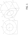
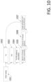
- the main body (12)(21) consists of a hollow cylindrical structure whose axial symmetry axis is coincident with the X axis, adapted to perform linear movements along the X axis and/or circular movements with respect to the same axis, where the elements (72) are oriented towards the axis of the main body (12).
- Said embodiment is represented in Figure 1 .
- R and R ' are the distances of each antenna with respect to any point of the X axis in a first and a second configuration of the apparatus.
- the value of distance R is not necessarily the same for each antenna being part of the apparatus. Instead, it is important that there is at least one antenna associated to an R value between 5 and 50 centimetres. In a completely analogous way, it is not necessary that all the antennas (72) of the apparatus are at the same distance from the reference point, but it is sufficient that at least one value of R', R' being different from R and in any case between 5 and 50 centimetres, is associated to at least one of them.
- the support (41) comprises two blades (42), on which one or more elements (72) are respectively housed, and such as to make a rotation movement on plane YZ around one fixing means (43), placed near one of the two ends of each blade (42).
- This configuration is shown in Figure 4 .
- blade one elongated element having two main ends is intended; at one of the two ends it is equipped with a fixing means, for example one pin (43) (44), around which it can perform rotational movements on the YZ plane, which in fact result in approaching or moving away movements of the antennas anchored thereto, with respect to a reference point, on the X axis.
- the support (41) comprises a single blade (42), on which at least two elements (72) are housed, such as to make one rotation movement on plane YZ around one fixing means (43), placed near one of the two ends of the blade (42).
- a single blade on which at least two elements (72) are housed, such as to make one rotation movement on plane YZ around one fixing means (43), placed near one of the two ends of the blade (42).
- the support (41) can house a multiplicity of antennas capable of performing linear movements along the radial direction with respect to the X axis, purely by way of example, by linear guides (42). Said embodiment is shown in Figure 5 .
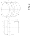
- the main body (31) comprises two plates interposed with each other and with respect to the X axis, each of said plates comprising at least one support (41) whose radio transmitting and radio receiving elements are oriented parallel with each other, along one second axis Z, perpendicular to the X axis. Said embodiment is shown in Figure 3 .
- the values of distances R and R ' are between 5 and 50 centimetres. That range of values implies that the distance between the two interposed plates is between 10 centimetres and about 1 meter, making the apparatus adaptable to specific applications.
- the distance of which between the plates is between 12 and 30 centimetres.
- the diameter of said plates it varies between 30 and 200 cm depending on the final application.
- the preferred dimensions of the present invention, in its third variant of Figure 3 are comprised between 60 and 90 cm as a trade-off between the coverage of the anatomical part concerned and the small dimensions, to facilitate clinical use.
- the main body (12)(21)(31) consists of a structure supporting all the internal components, made of materials compatible with the apparatus.
- materials such as for example the support (71) of the antennas (72 ) in Figure 7
- Preferred materials may, by way of example, include plastics, among which there is polytetrafluoroethylene (PTFE), synthetic polyamides such as Nylon and Kevlar, and specially synthesized fluoropolymers.
- the main body includes one shielding made of conductive materials with a thickness of between 0.02 and 10 mm in proximity of its external walls, which can also act as a structural support.
- the shielding isolates the internal environment of the main body and relative imaging area (11)(22)(33) from the external environment. As will be evident to those skilled in the art, this insulation contributes to the reduction of external electromagnetic disturbances, thereby improving the performance of the apparatus, but it is not necessary for its operation and can be omitted where the degree of electromagnetic interference, from the external environment to the apparatus and vice versa, can be overlooked.
- the shielding can be made of metallic or plastic materials loaded with magnetic or conductive powders.
- the main body is equipped with a mechanical structure for moving the antennas, shown in Figure 4 , Figure 5 and Figure 7 .
- the aforesaid structure allows the antennas to assume different positions as described below, in addition to supporting them together with the high frequency cables connected thereto.
- the parts of the structure located outside the main body are made of any material that has the required necessary mechanical features required for the correct operation of the apparatus and ensure the safety margins required by the existing standards.
- the parts of the structure placed inside the main body follow the indications mentioned above regarding the material features of the components exposed directly or indirectly to the electromagnetic waves generated by the apparatus towards the imaging area (11)(22)(33), where the subject is positioned.
- the aforementioned movement structure is also composed of the motors whose purpose is to move the structure supporting the antennas (41) and the various parts connected thereto (42)(43).
- the positioning of the motors preferably occurs outside the main body, to reduce noise and reflections internal thereto.
- the motors have sufficient torque to ensure correct movement, thereby limiting the temperatures reached by them, and providing the operating margins required by current regulations.
- the movement mechanical structure is also composed of the organs for transmitting the movement from the motors to itself and of motor control units required to preferably ensure an accurate movement and maintenance of the position at at least 1/10 of the vacuum wavelength associated to the maximum frequency emitted by the antennas in the internal band.
- the motor control units also ensure a smooth movement of the structure that does not cause harmful vibrations to the apparatus or that slow down its operations and verify the correct movement of the motors, after and during each control operation.
- the antennas whose purpose is to emit and receive electromagnetic waves from and to the patient, are preferably obtained on Printed Circuit Board (PCB) or Flexible Printed Circuit Board (FPCB) technology, to minimize the costs attributable thereto. More specifically, it is preferable that the aforementioned antennas are characterized by a directivity, understood as the ratio between electromagnetic energy transmitted in the direction of the subject with respect to the energy transmitted in the opposite direction, as high as possible in order to minimize interactions of the antenna with the main body, and to minimize reflections given by the latter.
- PCB Printed Circuit Board
- FPCB Flexible Printed Circuit Board
- the antennas must also preferably have an aperture at -3dB, defined as the width in degrees of the main electromagnetic energy emission lobe of the antenna itself when it reaches 50% from its peak, which is as narrow as possible in addition to minimizing the number of secondary lobes and their amplitudes, to focus the emitted energy only in the desired direction, thus increasing the performance of the apparatus having to consider a smaller wave interaction area.
- the high-frequency cables that connect the antennas to the transceiver unit, being located within the main body, preferably have a reduced cross section to minimize reflections in the main body.
- the aforementioned high frequency cables preferably have a diameter of the internal conductor large enough to allow the signal generated and received by the transceiver not to be too attenuated during its path.
- the high frequency cables are made of flexible materials that can guarantee nominal performance even after a high number of bending due to the continuous movement of the antennas.
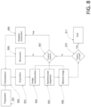
- the apparatus in addition to having a main body (12)(21)(31) comprises a connection system (34)(23)(13) which can include the transceiver unit, signal processing unit, the connection between the two just mentioned, the computing unit and the external network interface as well as the interaction interface.
- That system includes, among other components, the connection between the high frequency cables connected to the antennas and the transceiver.
- the transceiver can be achieved through a Vector Network Analyser (VNA), a combination of Spectrum Analyser and Function Generator or, as in the preferred implementation of the apparatus described here, by a Software Defined Radio (SDR).
- VNA Vector Network Analyser
- SDR Software Defined Radio
- the transceiver unit generates and receives all signals from and to the antennas and has a passband for the generation and reception of signals at least as wide as the internal band.
- the transceiver has a number of channels compatible with that of the antennas or a lower number, by exploiting additional external electronics (multiplexer).
- the additional external electronics has the purpose of guiding the signals to and from certain antennas, towards the individual channels of the transceiver module.
- the aforementioned high frequency multiplexers have a pass band at least equal to the internal band and preferably introduce the least number of distortions and attenuations to the signal circulating therein.
- Preferred parameters of the multiplexers for the present apparatus are an attenuation from the input port to the output port of less than 3dB, a return-loss greater than 15dB and an isolation between channel and channel greater than 20dB.
- the multiplexers have a number of output and input channels equal to at least the sum of the antennas and channels present in the transceiver module, in order to be able to direct each antenna on the desired transceiver module channel.
- the apparatus also includes the signal processing unit which, connected to the transceiver module, is responsible for filtering the noise collected by the antennas, by eliminating it from the signal to be analysed, calculating the flight times of the signals from antenna to antenna, extracting the parameters of scattering and transmission, eliminating from the signals all those features and defects due to the reflections, attenuations and distortions of the signal due to the single cables, multiplexers and to the main body itself.
- the signal processing unit can also take care of the application of the image extraction algorithm, where it is convenient and possible.
- Possible implementations of the signal processing unit are discrete component PCB boards, Computer, or the transceiver module itself in its implementation with VNA or Spectrum Analyser having an operating system installed therein, or, as in the preferred implementation of the apparatus here proposed, can be implemented using reprogrammable electronics in the form of a Field Programmable Gate Array (FPGA), or a Complex Programmable Logic Device (CPLD).
- FPGA Field Programmable Gate Array
- CPLD Complex Programmable Logic Device
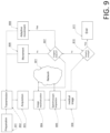
- the apparatus further includes a calculation unit whose purpose is the control of the movement of the antennas, the control of the status of the apparatus, the control of the status of the environment wherein the apparatus operates, the control of the condition of the subject, the communication of the apparatus with the network of apparatuses, communication of the apparatus with the user interface, and of all the operations necessary for the correct functioning of the apparatus.
- the computing unit preferably has numerous connections for communication with dedicated electronics, such as, for example, connections for 12C, SPI, USB, 10Gbit Ethernet, Pcie, Wifi and Bluetooth protocols and non-specialized adaptable connections.
- the computing unit deals with the movement of the antennas by sending commands to the motor control units which will then perform the movement providing telemetry signals, at the end and during the execution of the same.
- the apparatus may also include a power supply system and any batteries for its operation, once disconnected from the mains.
- the power supply system of the apparatus is responsible for converting the mains voltage into the voltages that can be used by the same as well as monitoring the mains voltage for dangerous conditions such as overvoltages, overcurrents, undervoltages or black outs. If one of these aforementioned danger conditions occurs, the power system disconnects the apparatus from the mains and switches it, where present, to battery-only operation as long as the dangerous condition persists.
- the apparatus may also include a unit for conditioning and monitoring the environment inside the main body with the aim of maintaining the relative humidity and the internal temperature between values that allow the apparatus and the components therein contained to function properly.
- the relative humidity inside the primary body should preferably be kept between 30 and 60%, while the internal temperature between 16 and 26 degrees.
- the air conditioning unit of the environment preferably filters the air entering the apparatus with anti-particulate filters to reduce the quantity of dust introduced therein, which could contribute to a reduction in the time between maintenance interventions, and damage the equipment or not allow to function optimally.
- a second conditioning unit of the external environment is used, in order to provide information to the conditioning unit of the internal environment, on how to best adapt it to improve the comfort of the subject and to avoid condensation phenomena.
- the apparatus may also comprise an external network interface, connected to the computing unit, for processing signals or on which the user interaction interface resides, with the purpose of communicating with the network (901).
- the interface is preferably obtained using physical media and/or protocols capable of guaranteeing a high upload bit rate toward the network and low response latency therefrom.
- the interface is made in standard Ethernet or optical fibre, the latter, as will be evident to the person skilled in the art, also intrinsically providing isolation from electromagnetic disturbances which would otherwise be brought from and to the apparatus along electrically conductive cables connected thereto.
- a further preferred implementation is obtained using wireless communication standards to ensure the operation of the apparatus even while moving or at locations where a wired network is not available.
- wireless communication can take place via standard 802.11ax, 802.11ac, 802.11b/g/n/a to a local network or with LTE, WiMAX, 5G standards toward a wide area network.
- the apparatus may comprise the apparatus user interface, with the aim of allowing the user to control the medical diagnostic functions of the apparatus as well as to control the state of the apparatus itself, the network and the environment wherein the apparatus is located.
- the interface is preferably made with digital colour screens connected to the computing unit and showing on said screens the controls necessary to operate the apparatus graphically.
- a second preferred implementation is achieved using a communicating wireless interface, by way of example with one of the protocols previously mentioned for the external interface, with computers already in the user's possession.
- the user apparatus interface is implemented in the form of graphic software that can be installed on commonly used devices, such as smartphones, tablets or personal computers.
- the acquisition of the subject's tomographic images is carried out by performing the following main steps:
- the value of the distance R is specific for each antenna and it is not required that all the antennas, in a first positioning, be associated with the same value of R; the same applies to the value of R' in the second positioning and to the P and P' values.
- spectral contrast it is meant the ability of the same to distinguish two tissues characterized by different dielectric physical properties. By way of example, the ability to distinguish between the presence of grey, white matter and cerebrospinal fluid.
- the number of acquisitions and the accuracy of the apparatus understood as spatial resolution, sharpness and spectral contrast, has a proportionality relationship with the number of acquisitions.
- the aforementioned accuracy of the apparatus is therefore a function of the acquisition time which, where necessary due to clinical doubts or doubts resulting from preliminary images, can be protracted over time or shortened if no clear doubts exists about the condition of the subject (810)(807).
- the acquisition times of the apparatus in the here detailed preferred configuration vary from a minimum of a few seconds for the first low-accuracy images up to require several minutes for the more detailed ones, depending on the requests that the user or the network make to confirm or deny a certain diagnostic hypothesis.
- the movement (808) of the antennas can be carried out by means of any of the systems described in the discussion of the apparatus or with similar systems without thereby going beyond the scope of the patent.
- a variant of the method also includes the step of conducting a spectroscopic investigation of the dielectric (805).
- One variant of the method also includes the step of conducting a comparison of the image obtained from the single apparatus with all those contained by a network of devices (901), for recognizing patterns or recurring structures that can speed up and improve the diagnosis in terms of accuracy.
- the antennas are arranged in such a way as to better resolve the area of interest to speed up the diagnosis (809).
- Figure 4d One example is given by Figure 4d .
- the user is asked to enter through the interface available thereto the symptoms, signs and the clinical picture of the subject, in addition to the diagnosis hypotheses that the user has of the subject's condition, to facilitate the analysis operations by the network.
- results of the analysis are presented to the user on the previously described interface (806) and are updated in real time, allowing the user to identify a zone to be solved with greater accuracy than the others or to conclude the analysis, once the required degree of detail and uncertainty on the image itself required (810)(811) has been reached.
- Each tissue the subject is composed of has distinctive dielectric features and properties [20][21] that define a Z wave impedance seen by the microwaves emitted by the antennas (72).
- an initial medium T0 which for the apparatus described here is the air inside the main body, and knowing the dielectric features of the tissues present in the body of the subject, by analysing the spectrum of reflections it is possible to extract information that not only regards the internal structure of the subject (tomography) but also the material composition of the aforementioned structure (spectrography), thus helping the user and the same network of apparatuses in the diagnostic phase.
- the instrument proceeds with the following proto-algorithm.
- two or more apparatuses according to the invention can be connected, in order to share the generated data and constitute an anonymous database capable of supporting the diagnosis by the user.
- the above mentioned database preferably comprises:
- the apparatuses in use in the context of the execution of a protocol, share with the network the data acquired on the subject and related information during the execution of the analysis itself.
- the data once collected from the network, are compared and analysed with the database available to the network and, where there are recurring features, the network generates an uncertainty estimate of the diagnostic hypothesis related to the aforementioned features and identifies the subsequent actions to be followed, to validate or not validate the hypothesis that the identified features are consistent with the analysis of the subject.
- the validation or dispute of the identified hypothesis is quantified in the increase or decrease of the uncertainty therewith associated.
- a possible action to be performed to validate or not validate the hypothesis includes the adaptive movement of the antennas to focus the apparatus on a certain area of the subject.
Landscapes
- Health & Medical Sciences (AREA)
- Life Sciences & Earth Sciences (AREA)
- Physics & Mathematics (AREA)
- General Physics & Mathematics (AREA)
- Molecular Biology (AREA)
- High Energy & Nuclear Physics (AREA)
- Spectroscopy & Molecular Physics (AREA)
- Engineering & Computer Science (AREA)
- Computer Vision & Pattern Recognition (AREA)
- Theoretical Computer Science (AREA)
- Biophysics (AREA)
- Surgery (AREA)
- Nuclear Medicine, Radiotherapy & Molecular Imaging (AREA)
- Pathology (AREA)
- Biomedical Technology (AREA)
- Heart & Thoracic Surgery (AREA)
- Medical Informatics (AREA)
- Radiology & Medical Imaging (AREA)
- Animal Behavior & Ethology (AREA)
- General Health & Medical Sciences (AREA)
- Public Health (AREA)
- Veterinary Medicine (AREA)
- Magnetic Resonance Imaging Apparatus (AREA)
- Apparatus For Radiation Diagnosis (AREA)
Claims (12)
- Vorrichtung zur Durchführung von Tomographien mittels Mikrowellen mit einem Hauptkörper (12, 21, 31), der sich um eine X-Achse entwickelt, umfassend:- eine Vielzahl von Funksende- und Funkempfangselementen (72);- mindestens einen Träger (41), der so konfiguriert ist, dass er die Vielzahl von Funksende- und Funkempfangselementen (72) aufnimmt, um eine erste Positionierung in einem Abstand R von einem gegebenen Punkt der X-Achse und eine zweite Positionierung zu ermöglichen, bei der mindestens ein der Elemente in einem Abstand R' von diesem Punkt liegt, wobei R' von R verschieden ist; wobei der Träger (41) eine kreisförmige Struktur ist, deren Mittelpunkt auf der X-Achse liegt;- wobei die Vielzahl von Funksende- und Funkempfangselementen (72) eine mehrere Antennen (72) sind, die Daten bezüglich der Reflexion und Absorption von elektromagnetischer Strahlung (EM) übertragen und erfassen, wobei mindestens eine der Antennen einem R-Wert zwischen 5 und 50 Zentimetern zugeordnet ist,- einen Mechanismus, der so konfiguriert ist, dass er die Antennen mittels des Trägers (41), der innerhalb oder außerhalb des Hauptkörpers installiert ist, zur ersten und zur zweiten Positionierung bewegt, und eine Recheneinheit zur Steuerung der Bewegung;- eine Signalverarbeitungseinheit, die so konfiguriert ist, dass sie die Aufgabe der von der Vielzahl von Antennen (72) empfangenen Signale zu analysieren und Signale in Richtung der Antennen (72) zu erzeugen;- eine Recheneinheit, die so konfiguriert ist, dass sie die Aufgabe der Anwendung eines Bildrekonstruktionsalgorithmus durchführt, der die Position der Antennen über den Mechanismus zum Bewegen der Antennen kontrolliert;- der eine Träger (41) weiter zwei Klingen (42) umfasst, die sich von der kreisförmigen Struktur in Richtung der X-Achse erstrecken, wobei jede Klinge (42) als längliches Element mit zwei Hauptenden ausgebildet ist und jedes Hauptende mit einem Befestigungsmittel (43, 44) ausgestattet ist, das eine Drehbewegung der Klingen in der YZ-Ebene ermöglicht, wobei die Klingen an einem ihrer Enden durch die Befestigungsmittel (44) verbunden sind, auf denen eine oder mehrere der mehreren Antennen (72) untergebracht sind, wobei die Befestigungsmittel (43) des anderen der beiden Enden jeder Klinge (42) die entsprechende Klinge (42) an dem Träger (41) befestigen.
- Vorrichtung nach Anspruch 1, wobei der Hauptkörper (12, 21) aus einer hohlzylindrischen Struktur besteht, deren Achse mit der X-Achse zusammenfällt, wobei die hohlzylindrische Struktur geeignet ist, lineare Bewegungen entlang der X-Achse und/oder kreisförmige Bewegungen in Bezug auf dieselbe Achse auszuführen, wobei die Elemente (72) auf die Achse des Hauptkörpers (12, 21) ausgerichtet sind.
- Vorrichtung nach Anspruch 2, wobei die hohlzylindrische Struktur eine Teilöffnung umfasst.
- Vorrichtung nach Anspruch 1, wobei der Hauptkörper (31) zwei Platten umfasst, die in Bezug aufeinander und in Bezug auf die X-Achse angeordnet sind, wobei jede dieser Platten mindestens einen Träger (41) umfasst, dessen Funksende- und Funkempfangselemente parallel zueinander und entlang einer zweiten Achse (Z) senkrecht zur X-Achse ausgerichtet sind.
- Vorrichtung nach einem der vorhergehenden Ansprüche, wobei der mindestens ein Träger (41) aus nichtmetallischen Materialien mit einer relativen dielektrischen Permeabilität nahe 1 und einem Dissipationsfaktor nahe 0 hergestellt ist.
- Vorrichtung nach einem der vorhergehenden Ansprüche, wobei der Hauptkörper (12, 21, 31) eine Abschirmung aus leitfähigem Material mit einer Dicke zwischen 0,02 mm und 10 mm aufweist, wobei die Abschirmung als strukturelle Unterstützung wirkt und sich in der Nähe der Außenwände des Hauptkörpers befindet.
- Vorrichtung nach einem der vorhergehenden Ansprüche, wobei die Antennen durch eine möglichst hohe Richtwirkung gekennzeichnet sind, um Wechselwirkungen der Antennen mit dem Hauptkörper zu minimieren und um Reflexionen durch den Hauptkörper zu minimieren.
- Vorrichtung nach einem der vorhergehenden Ansprüche, wobei genannte Antennen eine Apertur bei -3dB haben, die als die Breite in Grad einem Hauptlappen der elektromagnetischen Energieabstrahlung der Antenne definiert ist, wenn der Lappen 50 % von seiner Spitze erreicht, wobei der Emissionslappen so schmal wie möglich ist, um eine Anzahl von Nebenlappen und deren Amplituden zu minimieren.
- Vorrichtung nach einem der vorhergehenden Ansprüche, wobei die Vorrichtung eine Netzwerkschnittstelle umfasst, die mit der gennannten Recheneinheit verbunden ist, wobei die gennannte Netzwerkschnittstelle angepasst ist, um mit einem Netzwerk (901) der Vorrichtungen zu kommunizieren.
- Verfahren zur Tomographischen Bilderzeugung mit dem Vorrichtung nach einem der Ansprüche 1 bis 9, umfassend die folgenden Hauptschritte:a. Anordnen der Vorrichtung und Platzieren eines Subjekts (801) auf der X-Achse innerhalb des Abbildungsbereichs (11)(22)(33);b. Durchführung einer ersten Erfassung (802)(803) der vom Subjekt absorbierten und reflektierten Mikrowellen mit Hilfe der Funksende- und Funkempfangselemente (72), die in einem Abstand R von einem gegebenen Punkt und/oder in einer relativen Position P in Bezug auf die Achsen Z und Y der Achse angeordnet sind, und Rekonstruktion des erhaltenen Bildes (804)(805);c. Durchführung einer zweiten Erfassung (802)(803) der vom Subjekt absorbierten und reflektierten Mikrowellen mittels der Funksende- und Funkempfangselemente (72) in einem Abstand R' von diesem Punkt und/oder in einer relativen Position P' in Bezug auf die Achsen Z und Y, die sich von der relativen Position P unterscheidet, und Rekonstruktion des erhaltenen Bildes (804)(805).
- Verfahren zur Tomographischen Bilderzeugung nach Anspruch 10, weiter den Schritt der Durchführung einer dielektrischen spektroskopischen Untersuchung des Objekts durch genannte Vorrichtung umfasst.
- Verfahren zur Tomographischen Bilderzeugung nach Anspruch 10 oder 11, das den Schritt der Durchführung eines Vergleichs eines von einem die Vorrichtungen erhaltenen Bildes mit allen in dem Netz von Vorrichtungen (901) enthaltenen Bildern umfasst, um Muster oder wiederkehrende Strukturen zu erkennen.
Applications Claiming Priority (2)
| Application Number | Priority Date | Filing Date | Title |
|---|---|---|---|
| IT202000031724 | 2020-12-21 | ||
| PCT/IB2021/062085 WO2022137108A1 (en) | 2020-12-21 | 2021-12-21 | Apparatus and method for acquiring tomographic images using microwaves |
Publications (3)
| Publication Number | Publication Date |
|---|---|
| EP4262547A1 EP4262547A1 (de) | 2023-10-25 |
| EP4262547C0 EP4262547C0 (de) | 2024-12-18 |
| EP4262547B1 true EP4262547B1 (de) | 2024-12-18 |
Family
ID=75111682
Family Applications (1)
| Application Number | Title | Priority Date | Filing Date |
|---|---|---|---|
| EP21844400.8A Active EP4262547B1 (de) | 2020-12-21 | 2021-12-21 | Vorrichtung und verfahren zur tomographischen bilderzeugung mittels mikrowellen |
Country Status (3)
| Country | Link |
|---|---|
| US (1) | US12481077B2 (de) |
| EP (1) | EP4262547B1 (de) |
| WO (1) | WO2022137108A1 (de) |
Family Cites Families (8)
| Publication number | Priority date | Publication date | Assignee | Title |
|---|---|---|---|---|
| US20130166004A1 (en) | 2004-07-01 | 2013-06-27 | Joel Fallik | 3d microwave system and methods |
| WO2013005134A2 (en) * | 2011-07-01 | 2013-01-10 | University Of Manitoba | Imaging using probes |
| EP2922464B1 (de) * | 2012-11-21 | 2021-09-08 | Emtensor GmbH | Elektromagnetische tomografielösungen für abtastkopf |
| FR3006576B1 (fr) | 2013-06-06 | 2016-08-19 | Satimo Ind | Systeme d'imagerie medicale a emission/reception microondes |
| US10197508B2 (en) * | 2014-07-07 | 2019-02-05 | Univeristy Of Manitoba | Imaging using reconfigurable antennas |
| US10610122B2 (en) * | 2015-09-29 | 2020-04-07 | Avraham Suhami | Linear velocity imaging tomography |
| US9869641B2 (en) | 2016-04-08 | 2018-01-16 | Ellumen, Inc. | Microwave imaging device |
| WO2018217726A1 (en) | 2017-05-22 | 2018-11-29 | Washington University | Systems and methods for imaging, locating, and tracking a patient |
-
2021
- 2021-12-21 EP EP21844400.8A patent/EP4262547B1/de active Active
- 2021-12-21 US US18/268,942 patent/US12481077B2/en active Active
- 2021-12-21 WO PCT/IB2021/062085 patent/WO2022137108A1/en not_active Ceased
Also Published As
| Publication number | Publication date |
|---|---|
| EP4262547C0 (de) | 2024-12-18 |
| US20240053496A1 (en) | 2024-02-15 |
| US12481077B2 (en) | 2025-11-25 |
| EP4262547A1 (de) | 2023-10-25 |
| WO2022137108A1 (en) | 2022-06-30 |
Similar Documents
| Publication | Publication Date | Title |
|---|---|---|
| Bevacqua et al. | Millimeter-waves breast cancer imaging via inverse scattering techniques | |
| Epstein et al. | 3D parallel-detection microwave tomography for clinical breast imaging | |
| Stancombe et al. | Portable microwave head imaging system using software-defined radio and switching network | |
| Mobashsher et al. | On-site rapid diagnosis of intracranial hematoma using portable multi-slice microwave imaging system | |
| Mohammed et al. | Microwave system for head imaging | |
| Santorelli et al. | A time-domain microwave system for breast cancer detection using a flexible circuit board | |
| Ruvio et al. | Breast cancer detection using interferometric MUSIC: Experimental and numerical assessment | |
| EP0984722A1 (de) | Emit vorrichtung zur elektromagnetischen abbbildung und therapie | |
| KR101308409B1 (ko) | 물체형상 3차원 측정 장치 | |
| Abbosh et al. | Clinical electromagnetic brain scanner | |
| Lopez Rios et al. | Size‐adaptable 13‐channel receive array for brain MRI in human neonates at 3 T | |
| Thiel et al. | Combining magnetic resonance imaging and ultrawideband radar: A new concept for multimodal biomedical imaging | |
| Bourqui et al. | Measurement and analysis of microwave frequency signals transmitted through the breast | |
| US20240302293A1 (en) | Detecting and imaging using dielectric tomography | |
| Nohava et al. | A modular system of flexible receive-only coil arrays for 3 T Magnetic Resonance Imaging | |
| EP4262547B1 (de) | Vorrichtung und verfahren zur tomographischen bilderzeugung mittels mikrowellen | |
| Meaney et al. | Addressing multipath signal corruption in microwave tomography and the influence on system design and algorithm development | |
| US20140002106A1 (en) | Microwave imaging breast phantom, method for testing reliability of breast cancer diagnostic apparatus using the phantom, and breast cancer diagnostic apparatus including the phantom | |
| KR101082322B1 (ko) | 마이크로파 토모그램의 데이터를 다이콤 파일로 변환하는 방법 | |
| KR20190004511A (ko) | 테라헤르츠 전자기파를 이용한 영상 처리장치 | |
| US20240298914A1 (en) | Detecting and imaging using dielectric tomography | |
| KR102860258B1 (ko) | 인체 조직의 생물학적 변화 인식 시스템 | |
| Petrović et al. | Detection of Human Bodypart Abnormalities by Microwaves–A New Approach | |
| RU2103920C1 (ru) | Компьютерный томограф | |
| Sarwar | Microwave Imaging Specialized Hardware for Biomedical Applications |
Legal Events
| Date | Code | Title | Description |
|---|---|---|---|
| STAA | Information on the status of an ep patent application or granted ep patent |
Free format text: STATUS: UNKNOWN |
|
| STAA | Information on the status of an ep patent application or granted ep patent |
Free format text: STATUS: THE INTERNATIONAL PUBLICATION HAS BEEN MADE |
|
| PUAI | Public reference made under article 153(3) epc to a published international application that has entered the european phase |
Free format text: ORIGINAL CODE: 0009012 |
|
| STAA | Information on the status of an ep patent application or granted ep patent |
Free format text: STATUS: REQUEST FOR EXAMINATION WAS MADE |
|
| 17P | Request for examination filed |
Effective date: 20230721 |
|
| AK | Designated contracting states |
Kind code of ref document: A1 Designated state(s): AL AT BE BG CH CY CZ DE DK EE ES FI FR GB GR HR HU IE IS IT LI LT LU LV MC MK MT NL NO PL PT RO RS SE SI SK SM TR |
|
| DAV | Request for validation of the european patent (deleted) | ||
| DAX | Request for extension of the european patent (deleted) | ||
| GRAP | Despatch of communication of intention to grant a patent |
Free format text: ORIGINAL CODE: EPIDOSNIGR1 |
|
| STAA | Information on the status of an ep patent application or granted ep patent |
Free format text: STATUS: GRANT OF PATENT IS INTENDED |
|
| RIC1 | Information provided on ipc code assigned before grant |
Ipc: G01R 27/08 20060101ALI20240831BHEP Ipc: G01R 27/26 20060101ALI20240831BHEP Ipc: A61B 5/0507 20210101AFI20240831BHEP |
|
| INTG | Intention to grant announced |
Effective date: 20240920 |
|
| GRAS | Grant fee paid |
Free format text: ORIGINAL CODE: EPIDOSNIGR3 |
|
| GRAA | (expected) grant |
Free format text: ORIGINAL CODE: 0009210 |
|
| STAA | Information on the status of an ep patent application or granted ep patent |
Free format text: STATUS: THE PATENT HAS BEEN GRANTED |
|
| RAP3 | Party data changed (applicant data changed or rights of an application transferred) |
Owner name: ISTITUTO NAZIONALE DI FISICA NUCLEARE |
|
| AK | Designated contracting states |
Kind code of ref document: B1 Designated state(s): AL AT BE BG CH CY CZ DE DK EE ES FI FR GB GR HR HU IE IS IT LI LT LU LV MC MK MT NL NO PL PT RO RS SE SI SK SM TR |
|
| REG | Reference to a national code |
Ref country code: CH Ref legal event code: EP |
|
| REG | Reference to a national code |
Ref country code: DE Ref legal event code: R096 Ref document number: 602021023697 Country of ref document: DE |
|
| REG | Reference to a national code |
Ref country code: IE Ref legal event code: FG4D |
|
| U01 | Request for unitary effect filed |
Effective date: 20250110 |
|
| U07 | Unitary effect registered |
Designated state(s): AT BE BG DE DK EE FI FR IT LT LU LV MT NL PT RO SE SI Effective date: 20250120 |
|
| U20 | Renewal fee for the european patent with unitary effect paid |
Year of fee payment: 4 Effective date: 20250117 |
|
| PG25 | Lapsed in a contracting state [announced via postgrant information from national office to epo] |
Ref country code: HR Free format text: LAPSE BECAUSE OF FAILURE TO SUBMIT A TRANSLATION OF THE DESCRIPTION OR TO PAY THE FEE WITHIN THE PRESCRIBED TIME-LIMIT Effective date: 20241218 |
|
| PG25 | Lapsed in a contracting state [announced via postgrant information from national office to epo] |
Ref country code: NO Free format text: LAPSE BECAUSE OF FAILURE TO SUBMIT A TRANSLATION OF THE DESCRIPTION OR TO PAY THE FEE WITHIN THE PRESCRIBED TIME-LIMIT Effective date: 20250318 |
|
| PG25 | Lapsed in a contracting state [announced via postgrant information from national office to epo] |
Ref country code: GR Free format text: LAPSE BECAUSE OF FAILURE TO SUBMIT A TRANSLATION OF THE DESCRIPTION OR TO PAY THE FEE WITHIN THE PRESCRIBED TIME-LIMIT Effective date: 20250319 |
|
| PG25 | Lapsed in a contracting state [announced via postgrant information from national office to epo] |
Ref country code: RS Free format text: LAPSE BECAUSE OF FAILURE TO SUBMIT A TRANSLATION OF THE DESCRIPTION OR TO PAY THE FEE WITHIN THE PRESCRIBED TIME-LIMIT Effective date: 20250318 |
|
| PG25 | Lapsed in a contracting state [announced via postgrant information from national office to epo] |
Ref country code: SM Free format text: LAPSE BECAUSE OF FAILURE TO SUBMIT A TRANSLATION OF THE DESCRIPTION OR TO PAY THE FEE WITHIN THE PRESCRIBED TIME-LIMIT Effective date: 20241218 |
|
| PG25 | Lapsed in a contracting state [announced via postgrant information from national office to epo] |
Ref country code: PL Free format text: LAPSE BECAUSE OF FAILURE TO SUBMIT A TRANSLATION OF THE DESCRIPTION OR TO PAY THE FEE WITHIN THE PRESCRIBED TIME-LIMIT Effective date: 20241218 |
|
| PG25 | Lapsed in a contracting state [announced via postgrant information from national office to epo] |
Ref country code: ES Free format text: LAPSE BECAUSE OF FAILURE TO SUBMIT A TRANSLATION OF THE DESCRIPTION OR TO PAY THE FEE WITHIN THE PRESCRIBED TIME-LIMIT Effective date: 20241218 |
|
| PG25 | Lapsed in a contracting state [announced via postgrant information from national office to epo] |
Ref country code: IS Free format text: LAPSE BECAUSE OF FAILURE TO SUBMIT A TRANSLATION OF THE DESCRIPTION OR TO PAY THE FEE WITHIN THE PRESCRIBED TIME-LIMIT Effective date: 20250418 |
|
| PG25 | Lapsed in a contracting state [announced via postgrant information from national office to epo] |
Ref country code: SK Free format text: LAPSE BECAUSE OF FAILURE TO SUBMIT A TRANSLATION OF THE DESCRIPTION OR TO PAY THE FEE WITHIN THE PRESCRIBED TIME-LIMIT Effective date: 20241218 |
|
| PG25 | Lapsed in a contracting state [announced via postgrant information from national office to epo] |
Ref country code: CZ Free format text: LAPSE BECAUSE OF FAILURE TO SUBMIT A TRANSLATION OF THE DESCRIPTION OR TO PAY THE FEE WITHIN THE PRESCRIBED TIME-LIMIT Effective date: 20241218 |
|
| REG | Reference to a national code |
Ref country code: CH Ref legal event code: PL |
|
| PG25 | Lapsed in a contracting state [announced via postgrant information from national office to epo] |
Ref country code: MC Free format text: LAPSE BECAUSE OF FAILURE TO SUBMIT A TRANSLATION OF THE DESCRIPTION OR TO PAY THE FEE WITHIN THE PRESCRIBED TIME-LIMIT Effective date: 20241218 |
|
| PG25 | Lapsed in a contracting state [announced via postgrant information from national office to epo] |
Ref country code: CH Free format text: LAPSE BECAUSE OF NON-PAYMENT OF DUE FEES Effective date: 20241231 |
|
| PG25 | Lapsed in a contracting state [announced via postgrant information from national office to epo] |
Ref country code: IE Free format text: LAPSE BECAUSE OF NON-PAYMENT OF DUE FEES Effective date: 20241221 |
|
| PLBE | No opposition filed within time limit |
Free format text: ORIGINAL CODE: 0009261 |
|
| STAA | Information on the status of an ep patent application or granted ep patent |
Free format text: STATUS: NO OPPOSITION FILED WITHIN TIME LIMIT |
|
| 26N | No opposition filed |
Effective date: 20250919 |
|
| U20 | Renewal fee for the european patent with unitary effect paid |
Year of fee payment: 5 Effective date: 20251203 |
|
| PGFP | Annual fee paid to national office [announced via postgrant information from national office to epo] |
Ref country code: GB Payment date: 20251229 Year of fee payment: 5 |