EP4262943B1 - Détection de la présence de liquide dans un nébuliseur à membrane vibrante - Google Patents
Détection de la présence de liquide dans un nébuliseur à membrane vibrante Download PDFInfo
- Publication number
- EP4262943B1 EP4262943B1 EP21839916.0A EP21839916A EP4262943B1 EP 4262943 B1 EP4262943 B1 EP 4262943B1 EP 21839916 A EP21839916 A EP 21839916A EP 4262943 B1 EP4262943 B1 EP 4262943B1
- Authority
- EP
- European Patent Office
- Prior art keywords
- aerosol
- inhalation
- controller
- vibrator
- membrane
- Prior art date
- Legal status (The legal status is an assumption and is not a legal conclusion. Google has not performed a legal analysis and makes no representation as to the accuracy of the status listed.)
- Active
Links
Images


Classifications
-
- B—PERFORMING OPERATIONS; TRANSPORTING
- B05—SPRAYING OR ATOMISING IN GENERAL; APPLYING FLUENT MATERIALS TO SURFACES, IN GENERAL
- B05B—SPRAYING APPARATUS; ATOMISING APPARATUS; NOZZLES
- B05B12/00—Arrangements for controlling delivery; Arrangements for controlling the spray area
- B05B12/08—Arrangements for controlling delivery; Arrangements for controlling the spray area responsive to condition of liquid or other fluent material to be discharged, of ambient medium or of target ; responsive to condition of spray devices or of supply means, e.g. pipes, pumps or their drive means
- B05B12/081—Arrangements for controlling delivery; Arrangements for controlling the spray area responsive to condition of liquid or other fluent material to be discharged, of ambient medium or of target ; responsive to condition of spray devices or of supply means, e.g. pipes, pumps or their drive means responsive to the weight of a reservoir or container for liquid or other fluent material; responsive to level or volume of liquid or other fluent material in a reservoir or container
-
- A—HUMAN NECESSITIES
- A61—MEDICAL OR VETERINARY SCIENCE; HYGIENE
- A61M—DEVICES FOR INTRODUCING MEDIA INTO, OR ONTO, THE BODY; DEVICES FOR TRANSDUCING BODY MEDIA OR FOR TAKING MEDIA FROM THE BODY; DEVICES FOR PRODUCING OR ENDING SLEEP OR STUPOR
- A61M11/00—Sprayers or atomisers specially adapted for therapeutic purposes
- A61M11/005—Sprayers or atomisers specially adapted for therapeutic purposes using ultrasonics
-
- A—HUMAN NECESSITIES
- A61—MEDICAL OR VETERINARY SCIENCE; HYGIENE
- A61M—DEVICES FOR INTRODUCING MEDIA INTO, OR ONTO, THE BODY; DEVICES FOR TRANSDUCING BODY MEDIA OR FOR TAKING MEDIA FROM THE BODY; DEVICES FOR PRODUCING OR ENDING SLEEP OR STUPOR
- A61M15/00—Inhalators
- A61M15/0001—Details of inhalators; Constructional features thereof
- A61M15/0021—Mouthpieces therefor
-
- A—HUMAN NECESSITIES
- A61—MEDICAL OR VETERINARY SCIENCE; HYGIENE
- A61M—DEVICES FOR INTRODUCING MEDIA INTO, OR ONTO, THE BODY; DEVICES FOR TRANSDUCING BODY MEDIA OR FOR TAKING MEDIA FROM THE BODY; DEVICES FOR PRODUCING OR ENDING SLEEP OR STUPOR
- A61M15/00—Inhalators
- A61M15/0085—Inhalators using ultrasonics
-
- A—HUMAN NECESSITIES
- A61—MEDICAL OR VETERINARY SCIENCE; HYGIENE
- A61M—DEVICES FOR INTRODUCING MEDIA INTO, OR ONTO, THE BODY; DEVICES FOR TRANSDUCING BODY MEDIA OR FOR TAKING MEDIA FROM THE BODY; DEVICES FOR PRODUCING OR ENDING SLEEP OR STUPOR
- A61M16/00—Devices for influencing the respiratory system of patients by gas treatment, e.g. ventilators; Tracheal tubes
- A61M16/0003—Accessories therefor, e.g. sensors, vibrators, negative pressure
-
- B—PERFORMING OPERATIONS; TRANSPORTING
- B05—SPRAYING OR ATOMISING IN GENERAL; APPLYING FLUENT MATERIALS TO SURFACES, IN GENERAL
- B05B—SPRAYING APPARATUS; ATOMISING APPARATUS; NOZZLES
- B05B17/00—Apparatus for spraying or atomising liquids or other fluent materials, not covered by the preceding groups
- B05B17/04—Apparatus for spraying or atomising liquids or other fluent materials, not covered by the preceding groups operating with special methods
- B05B17/06—Apparatus for spraying or atomising liquids or other fluent materials, not covered by the preceding groups operating with special methods using ultrasonic or other kinds of vibrations
- B05B17/0607—Apparatus for spraying or atomising liquids or other fluent materials, not covered by the preceding groups operating with special methods using ultrasonic or other kinds of vibrations generated by electrical means, e.g. piezoelectric transducers
- B05B17/0638—Apparatus for spraying or atomising liquids or other fluent materials, not covered by the preceding groups operating with special methods using ultrasonic or other kinds of vibrations generated by electrical means, e.g. piezoelectric transducers spray being produced by discharging the liquid or other fluent material through a plate comprising a plurality of orifices
- B05B17/0646—Vibrating plates, i.e. plates being directly subjected to the vibrations, e.g. having a piezoelectric transducer attached thereto
-
- A—HUMAN NECESSITIES
- A61—MEDICAL OR VETERINARY SCIENCE; HYGIENE
- A61M—DEVICES FOR INTRODUCING MEDIA INTO, OR ONTO, THE BODY; DEVICES FOR TRANSDUCING BODY MEDIA OR FOR TAKING MEDIA FROM THE BODY; DEVICES FOR PRODUCING OR ENDING SLEEP OR STUPOR
- A61M15/00—Inhalators
- A61M15/0065—Inhalators with dosage or measuring devices
- A61M15/0068—Indicating or counting the number of dispensed doses or of remaining doses
- A61M15/0083—Timers
-
- A—HUMAN NECESSITIES
- A61—MEDICAL OR VETERINARY SCIENCE; HYGIENE
- A61M—DEVICES FOR INTRODUCING MEDIA INTO, OR ONTO, THE BODY; DEVICES FOR TRANSDUCING BODY MEDIA OR FOR TAKING MEDIA FROM THE BODY; DEVICES FOR PRODUCING OR ENDING SLEEP OR STUPOR
- A61M16/00—Devices for influencing the respiratory system of patients by gas treatment, e.g. ventilators; Tracheal tubes
- A61M16/0003—Accessories therefor, e.g. sensors, vibrators, negative pressure
- A61M2016/0015—Accessories therefor, e.g. sensors, vibrators, negative pressure inhalation detectors
- A61M2016/0018—Accessories therefor, e.g. sensors, vibrators, negative pressure inhalation detectors electrical
- A61M2016/0024—Accessories therefor, e.g. sensors, vibrators, negative pressure inhalation detectors electrical with an on-off output signal, e.g. from a switch
-
- A—HUMAN NECESSITIES
- A61—MEDICAL OR VETERINARY SCIENCE; HYGIENE
- A61M—DEVICES FOR INTRODUCING MEDIA INTO, OR ONTO, THE BODY; DEVICES FOR TRANSDUCING BODY MEDIA OR FOR TAKING MEDIA FROM THE BODY; DEVICES FOR PRODUCING OR ENDING SLEEP OR STUPOR
- A61M16/00—Devices for influencing the respiratory system of patients by gas treatment, e.g. ventilators; Tracheal tubes
- A61M16/0003—Accessories therefor, e.g. sensors, vibrators, negative pressure
- A61M2016/0027—Accessories therefor, e.g. sensors, vibrators, negative pressure pressure meter
-
- A—HUMAN NECESSITIES
- A61—MEDICAL OR VETERINARY SCIENCE; HYGIENE
- A61M—DEVICES FOR INTRODUCING MEDIA INTO, OR ONTO, THE BODY; DEVICES FOR TRANSDUCING BODY MEDIA OR FOR TAKING MEDIA FROM THE BODY; DEVICES FOR PRODUCING OR ENDING SLEEP OR STUPOR
- A61M2202/00—Special media to be introduced, removed or treated
- A61M2202/04—Liquids
- A61M2202/0468—Liquids non-physiological
-
- A—HUMAN NECESSITIES
- A61—MEDICAL OR VETERINARY SCIENCE; HYGIENE
- A61M—DEVICES FOR INTRODUCING MEDIA INTO, OR ONTO, THE BODY; DEVICES FOR TRANSDUCING BODY MEDIA OR FOR TAKING MEDIA FROM THE BODY; DEVICES FOR PRODUCING OR ENDING SLEEP OR STUPOR
- A61M2205/00—General characteristics of the apparatus
- A61M2205/02—General characteristics of the apparatus characterised by a particular materials
- A61M2205/0272—Electro-active or magneto-active materials
- A61M2205/0294—Piezoelectric materials
-
- A—HUMAN NECESSITIES
- A61—MEDICAL OR VETERINARY SCIENCE; HYGIENE
- A61M—DEVICES FOR INTRODUCING MEDIA INTO, OR ONTO, THE BODY; DEVICES FOR TRANSDUCING BODY MEDIA OR FOR TAKING MEDIA FROM THE BODY; DEVICES FOR PRODUCING OR ENDING SLEEP OR STUPOR
- A61M2205/00—General characteristics of the apparatus
- A61M2205/27—General characteristics of the apparatus preventing use
- A61M2205/276—General characteristics of the apparatus preventing use preventing unwanted use
-
- A—HUMAN NECESSITIES
- A61—MEDICAL OR VETERINARY SCIENCE; HYGIENE
- A61M—DEVICES FOR INTRODUCING MEDIA INTO, OR ONTO, THE BODY; DEVICES FOR TRANSDUCING BODY MEDIA OR FOR TAKING MEDIA FROM THE BODY; DEVICES FOR PRODUCING OR ENDING SLEEP OR STUPOR
- A61M2205/00—General characteristics of the apparatus
- A61M2205/33—Controlling, regulating or measuring
- A61M2205/3317—Electromagnetic, inductive or dielectric measuring means
-
- A—HUMAN NECESSITIES
- A61—MEDICAL OR VETERINARY SCIENCE; HYGIENE
- A61M—DEVICES FOR INTRODUCING MEDIA INTO, OR ONTO, THE BODY; DEVICES FOR TRANSDUCING BODY MEDIA OR FOR TAKING MEDIA FROM THE BODY; DEVICES FOR PRODUCING OR ENDING SLEEP OR STUPOR
- A61M2205/00—General characteristics of the apparatus
- A61M2205/33—Controlling, regulating or measuring
- A61M2205/3331—Pressure; Flow
-
- A—HUMAN NECESSITIES
- A61—MEDICAL OR VETERINARY SCIENCE; HYGIENE
- A61M—DEVICES FOR INTRODUCING MEDIA INTO, OR ONTO, THE BODY; DEVICES FOR TRANSDUCING BODY MEDIA OR FOR TAKING MEDIA FROM THE BODY; DEVICES FOR PRODUCING OR ENDING SLEEP OR STUPOR
- A61M2205/00—General characteristics of the apparatus
- A61M2205/33—Controlling, regulating or measuring
- A61M2205/3379—Masses, volumes, levels of fluids in reservoirs, flow rates
- A61M2205/3386—Low level detectors
-
- A—HUMAN NECESSITIES
- A61—MEDICAL OR VETERINARY SCIENCE; HYGIENE
- A61M—DEVICES FOR INTRODUCING MEDIA INTO, OR ONTO, THE BODY; DEVICES FOR TRANSDUCING BODY MEDIA OR FOR TAKING MEDIA FROM THE BODY; DEVICES FOR PRODUCING OR ENDING SLEEP OR STUPOR
- A61M2205/00—General characteristics of the apparatus
- A61M2205/50—General characteristics of the apparatus with microprocessors or computers
-
- A—HUMAN NECESSITIES
- A61—MEDICAL OR VETERINARY SCIENCE; HYGIENE
- A61M—DEVICES FOR INTRODUCING MEDIA INTO, OR ONTO, THE BODY; DEVICES FOR TRANSDUCING BODY MEDIA OR FOR TAKING MEDIA FROM THE BODY; DEVICES FOR PRODUCING OR ENDING SLEEP OR STUPOR
- A61M2205/00—General characteristics of the apparatus
- A61M2205/60—General characteristics of the apparatus with identification means
- A61M2205/6045—General characteristics of the apparatus with identification means having complementary physical shapes for indexing or registration purposes
-
- A—HUMAN NECESSITIES
- A61—MEDICAL OR VETERINARY SCIENCE; HYGIENE
- A61M—DEVICES FOR INTRODUCING MEDIA INTO, OR ONTO, THE BODY; DEVICES FOR TRANSDUCING BODY MEDIA OR FOR TAKING MEDIA FROM THE BODY; DEVICES FOR PRODUCING OR ENDING SLEEP OR STUPOR
- A61M2205/00—General characteristics of the apparatus
- A61M2205/82—Internal energy supply devices
- A61M2205/8206—Internal energy supply devices battery-operated
Definitions
- the present invention relates to a vibrating membrane nebulizer, and in particular to a method for detecting the presence of liquid in contact with the membrane.
- Aerosols for medical inhalation therapy generally comprise an active ingredient dissolved or suspended in an aerosolisable liquid, often water.
- a homogeneous distribution of aerosol droplets with a droplet size of around 5 ⁇ m is required in order to reach deep into the lungs.
- Vibrating membrane nebulizers are one type of device for producing such aerosols. These devices have an aerosol generator which comprises a vibrator, such as piezoelectric element which is excited at ultrasonic frequencies in order to induce vibration; a membrane (sometimes called a mesh or aperture plate), which has a large number of holes which typically have a diameter of 1 ⁇ m to 10 ⁇ m; and a reservoir, which supplies the liquid drug formulation to the membrane.
- DE10022795 and DE10203079 disclose breath-controlled vibrating membrane nebulizers.
- the nebulizer can indicate the end of the treatment session to the patient and / or turn off the vibrator automatically.
- WO2014/062175 and WO2015/091356 disclose methods for comparing measured and stored spectra, using averages and various mathematical techniques, to improve the reliability of empty detection.
- a comparison is typically performed at regular intervals while the membrane is being vibrated during the treatment session, until it is identified that the liquid has all been used up.
- nebulizer e.g. aerosol generator, driver electronics
- electro-mechanical behaviour can affect the electro-mechanical behaviour.
- methods which rely on comparisons with pre-set values can produce erroneous outcomes if the properties of the aerosol generator and / or driver electronics are differ from those onwhich the standard, stored values are based. Consequently, the vibrator could continue vibrating after the liquid has been used up, which could damage the membrane; or vibration could be stopped while liquid still remains to be aerosolized, so that the full dose is not delivered to the patient.
- improved methods for reliably detecting the presence of liquid in the reservoir / or in contact with the membrane can affect the electro-mechanical behaviour.
- the present invention provides an improved method for determining when the liquid to be nebulized has been used up.
- the inventor recognized that transient effects can be observed in the spectra immediately after vibration starts or stops, and that these can be used to reliably detect the presence or absence of liquid in contact with the membrane.
- the present invention provides a breath-actuated inhalation device comprising: an aerosol generator comprising a vibrator and a membrane; a reservoir for liquid to be aerosolized which is in fluid communication with the membrane; and a controller which provides a driver signal to drive the vibrator so that the membrane vibrates and generates an aerosol; wherein the controller is configured to:
- Previous empty detection methods that measure the values of an electrical parameter while the membrane is being vibrated rely on changes in the electro-mechanical properties of the aerosol generator as the volume of liquid decreases over time.
- the present invention relies on an effect which occurs when the membrane is vibrated intermittently, as in a breath-actuated nebulizer.
- the invention compares spectra obtained during periods of aerosol generation and periods of little or no aerosol generation to identify changes which arise from the formation or dissipation of a standing wave in the reservoir when vibration is started or stopped respectively.
- the invention is much less dependent on the properties of aerosol generator than the previous methods because it does not rely on a comparison with, for example, a stored spectrum; instead it detects a transient change that occurs only when a liquid is present. Consequently, the invention is more robust to variations in the hardware, changes in the hardware over the lifetime of the nebulizer and changes in external conditions.
- the controller may be configured to perform a first scan before each inhalation or period of aerosol generation to obtain a first spectrum; to subsequently perform a second scan during each inhalation or period of aerosol generation to obtain a second spectrum; and to compare the first and second spectra.
- the first scan may be performed immediately before the start of the period of aerosol generation.
- the second scan may be performed at least 50 or 100 ms after the start of the period of aerosol generation. This provides sufficient time for the standing wave to form, so that it is detectable in the second scan.
- the second scan may be performed less than 1000 ms or 500 ms after the start of the period of aerosol generation.
- the time delay between the first and second scans determines the point at which the absence of liquid can be detected. A smaller delay results in earlier empty detection, so the vibration of the membrane can be stopped sooner.
- the inhalation device is breath-actuated, i.e. the aerosol is not generated continuously, but only when the patient inhales.
- the device may comprise a channel having an air inlet opening and an aerosol outlet opening, and a pressure sensor which is pneumatically connected to the channel, and the controller may be configured to: receive a signal from the pressure sensor; sense an inhalation by a patient at the aerosol outlet opening on the basis of the signal from the pressure sensor; and initiate a period of aerosol generation in response to the inhalation.
- the controller may be configured to initiate a period of little or no aerosol generation at a pre-set time after the period of aerosol generation was initiated.
- the controller may be configured to sense when the patient ceases to inhale on the basis of the signal from the pressure sensor and to initiate a period of little or no aerosol generation in response to the cessation of inhalation.
- the method of the invention is particularly suitable for breath-actuated nebulizers, because there is no need to change to the manner in which the nebulizer operates since the aerosol is inherently generated intermittently.
- the aerosol generator may comprise a support member on which the vibrator and / or the membrane are mounted.
- the vibrator may be an annular piezoelectric element.
- the support element may be a transducer in the form of a hollow tubular body having a flange at or close to a first end onto which the piezoelectric element is attached, and a second end into or onto which the membrane is mounted.
- the device may comprise a filling chamber located above, and in fluid communication with, the support member, so that the filling chamber and the hollow tubular body together form the reservoir.
- the support member may comprise an essentially planar annulus or disk, and the membrane and / or the vibrator may be mounted on the support member, for example on opposite sides.
- the controller may be configured to determine a resonant frequency of the aerosol generator from the spectra, and to drive the vibrator at the resonant frequency, or at a frequency that is related to the resonant frequency, such as a fixed offset from the resonant frequency, during the periods of aerosol generation, other than the scans.
- the plurality of frequencies may comprise from about 10 or 15 kHz below the resonant frequency to about 10 or 15 kHz above the resonant frequency, for example from about 75 kHz to about 100 kHz.
- the controller may be configured to perform the comparison of the spectra by calculating an overlap function.
- the controller may further be configured to determine that no liquid is present in the reservoir if the value of the overlap function is above a threshold value.
- the controller may also be configured to cease driving the vibrator if the overlap function is above the threshold for a plurality of consecutive inhalations or periods of aerosol generation, such as three or five inhalations or periods of aerosol generation.
- the overlap function provides a robust comparison method.
- a first scan may be performed before each inhalationto obtain a first spectrum
- a second scan may subsequently be performed during each inhalation to obtain a second spectrum
- the first and second spectra may be compared.
- the periods of aerosol generation may be initiated in response to inhalation by the patient on the basis of a signal from the pressure sensor.
- the periods of little or no aerosol generation may be initiated at a pre-set time after the period of aerosol generation was initiated. Alternatively, the periods of little or no aerosol generation may be initiated in response to the cessation of inhalation by the patient.
- the spectra may be compared by calculating an overlap function. It may be determined that no liquid is present in the reservoir if the overlap function is above a threshold value. Driving the vibrator may cease if the overlap function is above the threshold value for a plurality of consecutive inhalations or periods of aerosol generation, such as three or five inhalations or periods of aerosol generation.
- the invention provides a breath-actuated inhalation device comprising: an aerosol generator comprising a vibrator and a membrane; a reservoir for liquid to be aerosolized which is in fluid communication with the membrane; and a controller which provides a driver signal to drive the vibrator so that the membrane vibrates and generates an aerosol in the channel; wherein the controller is configured to:
- a method of operating a breath-actuated inhalation device comprises:
- period of aerosol generation refers to a period of time in which the vibrator is mainly driven at the normal, intended frequency for generating an aerosol, which is typically at or near (e.g. within 2 kHz of) the resonant frequency.
- a period of aerosol generation may also include short periods of time in which one or more scans are performed.
- a period of aerosol generation may correspond to the typical length of a patient's inhalation, such as from 1 to 10s, 2 to 6s, or 3 to 5s.
- period of little or no aerosol generation refers to the intervals between periods of aerosol generation in which the vibrator is mainly not driven.
- a period of little or no aerosol generation may also include short periods of time in which one or more scans are performed. Since most of the scan frequencies are quite far (e.g. more than 2 kHz) from the resonant frequency, little or no aerosol is generated during a scan. Consequently, little or no aerosol is generated in a period of little or no aerosol generation.
- a period of little or no aerosol generation may correspond to the typical time between a patient's inhalations, such as from 1 to 10s, 2 to 6s, or 3 to 5s. Thus, intermittently driving the vibrator (at the normal driving frequency) results in alternate periods of aerosol generation and no aerosol generation.
- the term “scan” refers to the process of sequentially vibrating the vibrator at a large number of different frequencies in stepwise increments across a defined range, and measuring the value of an electrical parameter at some or all of the frequencies.
- the term “spectrum” refers to a graph which is obtained by plotting the measured values of the electrical parameter as a function of frequency.
- the electrical parameter may be the current, voltage, power, impedance and/or the current / voltage phase shift.
- the electrical parameter may be the current consumption of the vibrator, or of a power converter which provides the power to the vibrator, or the voltage drop at the vibrator.
- FIG. 1 shows an expanded view of a vibrating membrane nebulizer device, which is described in EP2724741 and WO2013/098334 .
- the device comprises three parts: a base unit, a mouthpiece component, and an aerosol head.
- the base unit 100 has one or more air inlet opening(s) in its rear end (not visible in Figure 1 ), an air outlet opening 102, a groove 103 for receiving the mouthpiece component 200, and one or more key lock members 104.
- a channel within the base unit (not visible in Figure 1 ) connects the air inlet opening(s) to the air outlet opening 102.
- the mouthpiece component 200 has an air inlet opening 201 which is attachable to the air outlet opening 102 of the base unit 100, a lateral opening 202 for receiving an aerosol generator 301, and an aerosol outlet opening 203.
- a channel 205 extends from the air inlet opening 201 to the aerosol outlet opening 203.
- the mouthpiece 200 is insertable into the groove 103 of the base unit 100.
- the aerosol head 300 comprises the aerosol generator 301, a filling chamber 302 for the liquid drug formulation to be aerosolized, which is in fluid contact with the upper end of the aerosol generator 301, and one or more key lock members 303 complementary to the key lock members 104 of the base unit 100.
- a lid 304 closes the filling chamber 302 and prevents contamination or spillage of the liquid during use.
- the base unit 100, the mouthpiece 200 and the aerosol head 300 are detachably connectible with one another.
- the device is assembled by inserting the mouthpiece 200 into the groove 103 in the base unit 100, then placing the aerosol head 300 over the mouthpiece 200 and engaging the key lock member(s) 303 of the aerosol head 300 with the key lock member(s) 104 of the base unit 100 by gentle pressure on both the aerosol head and the base unit.
- the aerosol generator 301 is positioned in the aerosol head 300 in such a way that when engaging the key lock member(s), the aerosol generator 301 is inserted into the lateral opening 202 of the mouthpiece 200.
- the base unit 100 has one or more indentation(s) 106 positioned at or near the groove 103, and the mouthpiece 200 has one or more positioning member(s) 204.
- the indentation(s) of the base unit are complementary to (i.e. shaped to receive) the positioning member(s) of the mouthpiece.
- an indentation is a depression whose "negative" shape is complementary to the "positive" shape of a positioning member, such as a flange, projection or the like.
- the indentations and positioning members act to position the mouthpiece correctly in the base unit.
- the indentation(s) and the positioning member(s) may be asymmetrical, so that the mouthpiece can only be inserted into the base unit in one way. This ensures that the device is assembled in such a manner that the position and orientation of the mouthpiece and base unit relative to each other are correct.
- the base unit contains a controller, such as a printed circuit board (PCB) which controls the operation of the nebulizer.
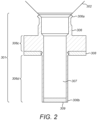
- FIG. 2 shows the aerosol generator, which is described in detail in WO2008/058941 . It comprises a vibrator, e.g. a piezoelectric element 308, a transducer body 306 and a membrane 309.
- the piezoelectric element is preferably an annular single or multi-layer ceramic, which vibrates the transducer body in a longitudinal mode.
- the transducer body is, for example made of stainless steel, titanium or aluminium, and encloses a cavity 307 which contains liquid to be aerosolized.
- the inside of the filling chamber 302 is conical so that liquid flows under gravity into the upstream end 306a of the transducer body and down into the cavity. Together, the filling chamber 302 and cavity 307 form a reservoir for the liquid.
- the membrane 309 is positioned at the downstream end 306b of the transducer body 306.
- the holes in the membrane may be formed by electroforming or by laser drilling, with openings normally in the range from about 1 ⁇ m to about 10 ⁇ m. Without vibration of the membrane, the balance of pressures, the shape of the holes and the nature of the material used for the membrane are such that the liquid does not seep out through the membrane. However, vibration of the membrane leads to the formation and emission of aerosol droplets through the holes.
- the membrane may be made of plastic, silicon, ceramic or more preferably metal, and may be affixed onto or into the downstream end of the transducer body by various means, such as gluing, brazing, crimping or laser welding.
- the membrane at least partially forms a dome in its central region, which causes the jet of nascent aerosol droplets to diverge and hence reduces the risk of droplet coalescence.
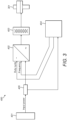
- a driver circuit 400 shown schematically in Figure 3 , generates the driver signal that excites the piezoelectric element and hence causes the membrane to vibrate, typically at a frequency in the range of 50 - 200 kHz.
- the input dc power is provided by a battery 401. This is converted into an ac driving voltage by a power converter 402 and a transformer 403.
- a closed-loop controller 404 controls the power supplied to the aerosol generator 301 by pulse width modulation, by varying the duty cycle, i.e. the fraction of time for which the power is supplied to the aerosol generator.
- the controller 404 inputs the driving frequency and the duty cycle to the power converter 402.
- the controller 404 also measures the current consumed by the aerosol generator 301, by means of a shunt resistor 405 in series with the input of the power converter 402.
- the effective power consumption and the absolute value of the impedance can be derived from the measured current.
- the aerosol generator is driven using near-resonance driving in which the frequency of the driver signal is as a fixed offset (such as 500Hz or 1 kHz) from the resonant frequency of the aerosol generator (typically around 85kHz).
- Excitation of the piezoelectric element causes micronic longitudinal displacements and / or deformations in a direction parallel to the symmetry axis of the transducer body 306.
- the transducer body has a region close to the piezoelectric element 308 with a relatively large wall thickness, which serves as a stress concentration zone 306c, and a region downstream thereof 306d with a relatively low wall thickness which serves as a deformation amplification zone. This configuration amplifies the vibrations or deformations of the transducer body 306 caused by the piezoelectric element 308.
- the piezoelectric element 308 is located at the level of, or adjacent to, the stress concentration zone 306c.
- the internal diameter of the transducer body at the deformation amplification zone may be the same as at the stress concentration zone, so that the differences in wall thickness correspond to different external diameters.
- the external diameter of the transducer body may be constant, while the inner diameters differ at the position of the two zones.
- the nebulizer is breath-actuated so that it only generates aerosol when the patient is inhaling. This avoids wasting the aerosol that is generated when the patient is exhaling, as can occur in nebulizers that operate in a continuous manner.
- a pressure sensor e.g. a barometric pressure sensor
- the pressure sensor measures the pressure in the channel, and sends a signal representing the pressure to the controller.
- the controller determines that the patient has begun to inhale, and causes the piezoelectric element, and hence the membrane to vibrate, so that aerosol droplets are generated.
- the aerosol generated by the membrane 309 is released into the channel 205.
- Air enters through the air inlets in the base unit and passes through the channel in the base unit, the air outlet opening 102, and the air inlet opening 201 of the mouthpiece component, and into the channel 205 where mixes it with the aerosol.
- the air and aerosol then flow along the channel 205, out through the aerosol outlet opening 203 of the mouthpiece and into the patient's airway.
- the controller stops the aerosol generation when a pre-set length of time (for example 3s) has elapsed since the aerosol generation started.
- the pre-set length of time may correspond to the length of a typical inhalation, and may be configurable by the patient. Alternatively, the pre-set length of time may be shorter than a typical inhalation, so that in the final part of the inhalation, the patient receives air but no aerosol. This ensures that the aerosol reaches the central and lower parts of the patient's airway, but is not delivered to the patient's upper airway (e.g. the throat) where it would be ineffective.
- the controller could alternatively detect when the patient ceases to inhale by sensing the increase in pressure in the channel, and then stop aerosol generation.
- the resonant frequency of the aerosol generator changes over the duration of a treatment as the amount of liquid in the reservoir decreases.
- an electrical parameter which relates to the vibration of the aerosol generator is measured, for example the current consumption of the aerosol generator.
- the resulting graph of current as a function of frequency (the spectrum) has a peak at the resonant frequency of the aerosol generator.
- the scans take, for example, about 70 ms to perform.
- the aerosol generator does not operate at the optimum frequency, so the aerosol output rate drops. Consequently, almost all of the aerosol is generated in the time between the scans (430 ms in this case).
- the point at which the membrane becomes dry can be determined from the scans, for example from changes in the shape of the spectrum as a function of time, or in comparison to a standard spectrum, as described, for example in US2006/0102172 , US9272101 , WO2014/062175 and WO2015/091356 .
- these methods may produce erroneous results as a result of variations in the hardware, changes in the hardware over the lifetime of the nebulizer and changes in external conditions.
- the invention is based on a different effect which is independent of these variations, and so is more reliable.
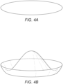
- the nebulizer is switched off, the liquid in the cavity has a flat surface with a meniscus around the edge.
- the aerosol generator is vibrated at or close to its resonant frequency, a standing wave is formed in the liquid within about 50ms.
- the inverse effect is observed when vibration is stopped, although it takes longer (about 1s) for the wave to dissipate and the liquid surface to become flat again.
- Figure 4 shows schematic drawings of the surface of the liquid in the reservoir of a nebulizer of Figure 1 .
- Figure 4A shows the liquid before vibration was started; the surface is flat, i.e. there is a uniform distribution of the liquid across the transducer body.
- Figure 4B shows the surface during vibration; the liquid has formed a standing wave with a peak in the centre.
- Figures 5 and 6 show spectra obtained with the nebulizer of Figure 1 , by vibrating the membrane at a series of different frequencies from 75 kHz to 100 kHz in steps of 0.1khZ with a constant duty cycle, and measuring the current consumption of the power converter at each frequency. Seven scans, each taking 70ms, were performed at 500ms intervals. Between the scans, the membrane was vibrated at its normal near-resonant driving frequency for 430ms.
- Figure 5 shows the resulting spectra when no liquid was present.
- the main peak at 89.5kHz, at which the maximum current consumption occurs, is the resonant frequency of the aerosol generator.
- each spectrum is plotted as a separate line, they almost exactly overlie each other, and it is not possible to distinguish between them.
- Figure 6 shows the spectra obtained when liquid was present. There are differences between the general shape of the spectra compared to those of Figure 5 . Firstly, the main resonance peak is at a lower frequency (86.5 kHz) and is slightly broader than in Figure 5 , i.e. the resonance is slightly less sharp when liquid is present. These changes in the main resonance peak over the course of a number of inhalations form the basis for some known methods of empty detection. Secondly, the smaller peak has disappeared.
- the invention compares a spectrum obtained when aerosol is not being generated with a spectrum obtained after aerosol generation has begun. If no liquid is present, there is no standing wave so the spectra before and during vibration are the same. However, if liquid is present, the spectra are different: the first spectrum reflects the initial, flat liquid surface and the subsequent spectrum reflects the standing wave.
- the effect is most clearly seen between the first and second spectra because most of the redistribution of liquid occurs quickly, typically within about 50ms, i.e. before the second spectrum is obtained. This difference is also present when comparing the first spectrum with any subsequent spectrum.
- the spectra are also affected by the liquid fill level in the reservoir. There is very little change in the fill level between the times at which the first and second spectra are recorded.
- the difference between them would reflect the decrease in the liquid fill level as well as the formation of the standing wave.
- this is less preferred because these spectra reflect a combination of the two effects.
- the degree to which two spectra match each other can be represented by an "overlap function".
- the overlap function can be calculated as the reciprocal of the sum of the absolute value of the difference between the spectra at each frequency.
- the overlap function has a low value.
- the overlap function has a higher value.
- a representative treatment operation was performed using the nebulizer of Figure 1 to nebulize 4mL of 0.9% saline solution.
- Figure 7 shows a graph of the overlap function for each inhalation in the representative treatment operation.
- the overlap function is approximately constant at a low value (mostly below 1000) for the first 180 inhalations. This indicates that the first and second spectra differ in these inhalations, because a standing wave is formed in the liquid when the membrane starts to vibrate. Thereafter, the value of the overlap function rises sharply, indicating that the first and second spectra are becoming more similar in breaths 180 - 190, i.e. the standing wave effect is disappearing because there is very little liquid remaining.
- a pre-set threshold can be used to determine the point at which the reservoir no longer contains liquid.
- a threshold value of e.g. 5000 would be suitable in Figure 7 .
- the determination of when the liquid has been used up can be made more robust by only deciding that the reservoir is empty if the value of the overlap function is greater than the threshold for a number of consecutive breaths (e.g. three or five breaths). This prevents incorrect determinations resulting from noise or an erroneous measurement in the overlap function.
- first and second spectra means that the overlap function can be calculated slightly sooner than if a subsequent spectrum were used, because the time delay between the first and second spectra (0.5s) is smaller than, for example, between the first and seventh spectra (3s). This has the advantage that the determination of when the threshold has been crossed can be made earlier (by 2.5s in this example), so that the vibration of the membrane is stopped as soon as possible.
- the invention is particularly suitable for breath-actuated nebulizers, since the vibrator is necessarily operated intermittently, i.e. only when the patient inhales. It could also be used in nebulizers that normally operate continuously, by introducing periods in which the vibrator is switched off.
- the duration of the off periods should be at least about 0.5s, preferably 1s, in order to allow the liquid to return to a flat surface before vibration is re-commenced.
- the overlap function in Figure 7 was obtained by comparing the spectra immediately before and during a period of aerosol generation, so that the difference between them reflects the formation of a standing wave when the membrane starts to vibrate.
- a spectrum obtained during a period of aerosol generation is compared with a spectrum obtained during the preceding period of little or no aerosol generation.
- the overlap function could equally be obtained by comparing a spectrum obtained during a period of aerosol generation with a spectrum obtained during the succeeding period of little or no aerosol generation.
- the difference between the spectra during and after aerosol generation reflects the dissipation of the standing wave when the membrane ceases to vibrate. This requires that sufficient time has elapsed after vibration ceases before the spectrum is measured.
- the standing wave takes longer to dissipate (500 - 1000ms) than it takes to form (about 50ms). This is not a concern in a breath-actuated inhaler, since the time between inhalations is usually more than 1s.
- a nebulizer which is not breath-actuated the periods in which the membrane is not vibrated would need to be longer to allow for dissipation, which would result in a reduction in the overall aerosol output rate.
- the invention is especially suitable for nebulizers of the type shown in Figure 1 , in which regular scans are performed in order to determine the resonant frequency.
- the method of the invention can use the spectra from these scans, and extract additional information from them. Hence implementing the invention requires only some additional analysis of the spectra, and there is no need to change the way in which the nebulizer is operated.
- the principle of the invention applies to any vibrating membrane nebulizer in which the membrane is in contact with a liquid reservoir in which a standing wave can be formed.
- the invention can be used with other types of nebulizer, for example those described in WO2012/046220 , WO2015/193432 , WO2015/091356 , US2006/0102172 and US9027548 .
- These nebulizers do not have a transducer in the form of a hollow tubular body. Instead, the membrane is mounted directly on the piezoelectric element, or there is an annular, planar support member on which the membrane and / or the piezoelectric element are mounted.
- the method employed in the device of the invention could be used instead of, or in addition to other empty detection methods (for example as in US2006/0102172 , US9272101 , WO2014/062175 and WO2015/091356 which measure the changes in an electrical parameter as the volume of liquid decreases over time) to provide a combined decision process for determining whether membrane is dry. Since the method employed in the device of the invention relies on a completely different effect from these other methods, it provides completely independent information on whether liquid is present. Thus the combination of the method employed in the device of the invention and a different method provides particularly robust empty detection.
Landscapes
- Health & Medical Sciences (AREA)
- Engineering & Computer Science (AREA)
- Life Sciences & Earth Sciences (AREA)
- Animal Behavior & Ethology (AREA)
- Anesthesiology (AREA)
- Biomedical Technology (AREA)
- Heart & Thoracic Surgery (AREA)
- Hematology (AREA)
- Veterinary Medicine (AREA)
- Public Health (AREA)
- General Health & Medical Sciences (AREA)
- Pulmonology (AREA)
- Bioinformatics & Cheminformatics (AREA)
- Emergency Medicine (AREA)
- Special Spraying Apparatus (AREA)
- Investigating Or Analysing Biological Materials (AREA)
Claims (10)
- Dispositif d'inhalation actionné par la respiration comprenant un générateur d'aérosol (301) comportant un vibreur (308) et une membrane (309), un réservoir (302, 307) pour un liquide à transformer en aérosol qui est en communication fluidique avec la membrane, et un dispositif de commande (404) qui fournit un signal d'attaque pour attaquer le vibreur de sorte que la membrane vibre et génère un aérosol, dans lequel le dispositif de commande est configuré pour :• attaquer le vibreur par intermittence de sorte que le générateur d'aérosol subisse de manière répétée des périodes de génération d'aérosol pendant les inhalations d'un patient et des périodes de génération d'aérosol faible ou nulle précédant et/ou suivant les inhalations ; caractérisé en ce que le dispositif de commande est en outre configuré pour :• effectuer des balayages dans lesquels la membrane est mise en vibration à une pluralité de fréquences, et dans lesquels au moins un paramètre électrique du vibreur est mesuré à la pluralité de fréquences pour fournir un spectre ; dans lequel les balayages sont effectués pendant les inhalations et pendant les périodes précédant ou suivant les inhalations ;• comparer un spectre obtenu pendant une inhalation avec un spectre obtenu pendant la période précédant ou suivant cette inhalation ;• déterminer si un liquide est présent dans le réservoir sur la base de la comparaison des spectres ; et• cesser d'attaquer le vibreur si le dispositif de commande détermine qu'aucun liquide n'est présent.
- Dispositif d'inhalation selon la revendication 1 dans lequel le dispositif de commande est configuré pour effectuer un premier balayage avant chaque inhalation pour obtenir un premier spectre, pour effectuer ensuite un second balayage pendant chaque inhalation pour obtenir un second spectre, et pour comparer les premier et second spectres.
- Dispositif d'inhalation selon la revendication 1 ou la revendication 2, qui comprend un canal (205) comportant une ouverture d'entrée d'air (201) et une ouverture de sortie d'aérosol (203), et un capteur de pression qui est pneumatiquement relié au canal, dans lequel le dispositif de commande est configuré pour détecter une inhalation par un patient au niveau de l'ouverture de sortie d'aérosol sur la base d'un signal provenant du capteur de pression, et pour commencer une période de génération d'aérosol en réponse à l'inhalation.
- Dispositif d'inhalation selon la revendication 3, dans lequel le dispositif de commande est configuré pour commencer une période de génération d'aérosol faible ou nulle à un moment prédéfini après le commencement de la période de génération d'aérosol.
- Dispositif d'inhalation selon l'une quelconque des revendications 1 à 4, dans lequel le générateur d'aérosol comporte un élément de support (306) comprenant un corps tubulaire creux ayant une bride au niveau ou près d'une première extrémité sur laquelle est fixé le vibreur (308), et une seconde extrémité (306b) dans ou sur laquelle est montée la membrane (309), et dans lequel le dispositif comprend une chambre de remplissage (302) au-dessus de l'élément de support, de sorte que la chambre de remplissage (302) et le corps tubulaire creux (307) forment ensemble le réservoir.
- Dispositif d'inhalation selon l'une quelconque des revendications 1 à 5, dans lequel le dispositif de commande est configuré pour déterminer la fréquence de résonance du générateur d'aérosol à partir des spectres, et pour attaquer le vibreur à la fréquence de résonance, ou à une fréquence relative à la fréquence de résonance, pendant les périodes de génération d'aérosol autres que les balayages.
- Dispositif d'inhalation selon la revendication 6, dans lequel la pluralité de fréquences comprend d'environ 10 ou 15 kHz en dessous de la fréquence de résonance à environ 10 ou 15 kHz au-dessus de la fréquence de résonance, par exemple de 75 kHz à environ 100 kHz.
- Dispositif d'inhalation selon l'une quelconque des revendications 1 à 7, dans lequel le dispositif de commande est configuré pour comparer les spectres en calculant une fonction de chevauchement.
- Dispositif d'inhalation selon la revendication 8, dans lequel le dispositif de commande est configuré pour déterminer qu'aucun liquide n'est présent dans le réservoir si la fonction de chevauchement est supérieure à une valeur seuil.
- Dispositif d'inhalation selon la revendication 9, dans lequel le dispositif de commande est configuré pour cesser d'attaquer le vibreur si la fonction de chevauchement est supérieure à la valeur seuil pendant une pluralité de périodes consécutives de génération d'aérosol, telles que trois ou cinq périodes.
Applications Claiming Priority (2)
| Application Number | Priority Date | Filing Date | Title |
|---|---|---|---|
| EP20214452 | 2020-12-16 | ||
| PCT/EP2021/085980 WO2022129220A1 (fr) | 2020-12-16 | 2021-12-15 | Détection de la présence de liquide dans un nébuliseur à membrane vibrante |
Publications (2)
| Publication Number | Publication Date |
|---|---|
| EP4262943A1 EP4262943A1 (fr) | 2023-10-25 |
| EP4262943B1 true EP4262943B1 (fr) | 2024-08-07 |
Family
ID=73854740
Family Applications (1)
| Application Number | Title | Priority Date | Filing Date |
|---|---|---|---|
| EP21839916.0A Active EP4262943B1 (fr) | 2020-12-16 | 2021-12-15 | Détection de la présence de liquide dans un nébuliseur à membrane vibrante |
Country Status (6)
| Country | Link |
|---|---|
| US (1) | US20240058556A1 (fr) |
| EP (1) | EP4262943B1 (fr) |
| JP (1) | JP7596541B2 (fr) |
| CN (1) | CN116600842B (fr) |
| CA (1) | CA3201509A1 (fr) |
| WO (1) | WO2022129220A1 (fr) |
Families Citing this family (1)
| Publication number | Priority date | Publication date | Assignee | Title |
|---|---|---|---|---|
| ES2973682B2 (es) * | 2022-11-10 | 2025-10-01 | Zobele Espana Sa | Dispositivo para la difusión de sustancias volátiles |
Citations (2)
| Publication number | Priority date | Publication date | Assignee | Title |
|---|---|---|---|---|
| US20060102172A1 (en) * | 2002-10-30 | 2006-05-18 | Pari Gmbh Spezialisten Fur Effektive Inhalation | Inhalation therapy device |
| WO2015091356A1 (fr) * | 2013-12-16 | 2015-06-25 | Pari Pharma Gmbh | Dispositif d'administration en aérosol et procédé de fonctionnement du dispositif d'administration en aérosol |
Family Cites Families (13)
| Publication number | Priority date | Publication date | Assignee | Title |
|---|---|---|---|---|
| US7628339B2 (en) | 1991-04-24 | 2009-12-08 | Novartis Pharma Ag | Systems and methods for controlling fluid feed to an aerosol generator |
| DE10022795B4 (de) * | 2000-05-10 | 2005-04-14 | Pari GmbH Spezialisten für effektive Inhalation | Atemgesteuertes Inhalationstherapiegerät |
| DE10203079A1 (de) * | 2002-01-28 | 2003-08-21 | Pari Gmbh | Atemflussmessvorrichtung |
| DE102005006374B3 (de) | 2005-02-11 | 2006-07-20 | Pari GmbH Spezialisten für effektive Inhalation | Aerosolerzeugungsvorrichtung und Inhalationstherapiegerät mit einer derartigen Vorrichtung |
| FR2908329B1 (fr) | 2006-11-14 | 2011-01-07 | Telemaq | Dispositif et methode de distribution de fluide par ultrasons |
| ATE523262T1 (de) * | 2007-10-10 | 2011-09-15 | Ep Systems Sa | Adaptives steuersystem für einen piezoelektrischen aktor |
| MX2012008347A (es) | 2010-01-19 | 2012-08-08 | Nektar Therapeutics | Identificacion de elementos secos del nebulizador. |
| NO3181243T3 (fr) | 2010-10-04 | 2018-08-11 | ||
| PT2797652T (pt) | 2011-12-27 | 2019-02-19 | Vectura Gmbh | Dispositivo para inalação com sistema de feedback |
| EP2724741B1 (fr) | 2012-10-26 | 2017-06-14 | Vectura GmbH | Dispositif d'inhalation destiné à être utilisé dans une thérapie par aérosol |
| CN104812429B (zh) * | 2012-10-17 | 2017-09-26 | 内克塔治疗公司 | 用于确认干雾化器元件的方法和系统 |
| CN105592935B (zh) | 2013-07-24 | 2018-10-16 | 斯坦福设备有限公司 | 喷雾器振动孔板驱动频率控制及监测 |
| EP2957349A1 (fr) | 2014-06-20 | 2015-12-23 | PARI Pharma GmbH | Générateur d'aérosol et dispositif de distribution d'aérosol comprenant le générateur |
-
2021
- 2021-12-15 CA CA3201509A patent/CA3201509A1/fr active Pending
- 2021-12-15 US US18/268,079 patent/US20240058556A1/en active Pending
- 2021-12-15 WO PCT/EP2021/085980 patent/WO2022129220A1/fr not_active Ceased
- 2021-12-15 CN CN202180084279.4A patent/CN116600842B/zh active Active
- 2021-12-15 EP EP21839916.0A patent/EP4262943B1/fr active Active
- 2021-12-15 JP JP2023537143A patent/JP7596541B2/ja active Active
Patent Citations (2)
| Publication number | Priority date | Publication date | Assignee | Title |
|---|---|---|---|---|
| US20060102172A1 (en) * | 2002-10-30 | 2006-05-18 | Pari Gmbh Spezialisten Fur Effektive Inhalation | Inhalation therapy device |
| WO2015091356A1 (fr) * | 2013-12-16 | 2015-06-25 | Pari Pharma Gmbh | Dispositif d'administration en aérosol et procédé de fonctionnement du dispositif d'administration en aérosol |
Also Published As
| Publication number | Publication date |
|---|---|
| JP2024503582A (ja) | 2024-01-26 |
| WO2022129220A1 (fr) | 2022-06-23 |
| US20240058556A1 (en) | 2024-02-22 |
| CN116600842A (zh) | 2023-08-15 |
| JP7596541B2 (ja) | 2024-12-09 |
| CA3201509A1 (fr) | 2022-06-23 |
| CN116600842B (zh) | 2025-11-25 |
| EP4262943A1 (fr) | 2023-10-25 |
Similar Documents
| Publication | Publication Date | Title |
|---|---|---|
| EP0432992B1 (fr) | Appareil de distribution | |
| US6978779B2 (en) | Vibrating element liquid discharging apparatus having gas pressure sensing | |
| US6546927B2 (en) | Methods and apparatus for controlling piezoelectric vibration | |
| EP2744541B1 (fr) | Nébuliseur, unité de commande pour le commander et procédé d'actionnement d'un nébuliseur | |
| JP6455961B2 (ja) | ネブライザ、ネブライザを制御する制御ユニット及びネブライザの制御方法 | |
| US20100154793A1 (en) | Medicine ejection device | |
| JP2000225188A (ja) | 超音波ネブライザ | |
| US20230390507A1 (en) | Method for detecting the presence of liquid in a vibrating membrane nebulizer | |
| EP4262943B1 (fr) | Détection de la présence de liquide dans un nébuliseur à membrane vibrante | |
| CA3211358A1 (fr) | Dispositif de generation d'aerosol utilisant un transducteur vibrant et une alimentation en liquide commandee | |
| EP4015094A1 (fr) | Nébuliseur à membrane vibrante | |
| JP2010059792A (ja) | 流体噴射装置、流体噴射ユニット、制御装置、流体噴射装置の制御方法および手術装置 | |
| KR20250038748A (ko) | 작은 스텝 크기 및 고해상도 에어로졸 생성 시스템 및 방법 | |
| US20240226462A1 (en) | Droplet delivery device with high dose confidence mode |
Legal Events
| Date | Code | Title | Description |
|---|---|---|---|
| STAA | Information on the status of an ep patent application or granted ep patent |
Free format text: STATUS: UNKNOWN |
|
| STAA | Information on the status of an ep patent application or granted ep patent |
Free format text: STATUS: THE INTERNATIONAL PUBLICATION HAS BEEN MADE |
|
| PUAI | Public reference made under article 153(3) epc to a published international application that has entered the european phase |
Free format text: ORIGINAL CODE: 0009012 |
|
| STAA | Information on the status of an ep patent application or granted ep patent |
Free format text: STATUS: REQUEST FOR EXAMINATION WAS MADE |
|
| 17P | Request for examination filed |
Effective date: 20230620 |
|
| AK | Designated contracting states |
Kind code of ref document: A1 Designated state(s): AL AT BE BG CH CY CZ DE DK EE ES FI FR GB GR HR HU IE IS IT LI LT LU LV MC MK MT NL NO PL PT RO RS SE SI SK SM TR |
|
| DAV | Request for validation of the european patent (deleted) | ||
| DAX | Request for extension of the european patent (deleted) | ||
| GRAP | Despatch of communication of intention to grant a patent |
Free format text: ORIGINAL CODE: EPIDOSNIGR1 |
|
| STAA | Information on the status of an ep patent application or granted ep patent |
Free format text: STATUS: GRANT OF PATENT IS INTENDED |
|
| GRAJ | Information related to disapproval of communication of intention to grant by the applicant or resumption of examination proceedings by the epo deleted |
Free format text: ORIGINAL CODE: EPIDOSDIGR1 |
|
| STAA | Information on the status of an ep patent application or granted ep patent |
Free format text: STATUS: REQUEST FOR EXAMINATION WAS MADE |
|
| INTG | Intention to grant announced |
Effective date: 20240513 |
|
| GRAP | Despatch of communication of intention to grant a patent |
Free format text: ORIGINAL CODE: EPIDOSNIGR1 |
|
| STAA | Information on the status of an ep patent application or granted ep patent |
Free format text: STATUS: GRANT OF PATENT IS INTENDED |
|
| INTC | Intention to grant announced (deleted) | ||
| GRAS | Grant fee paid |
Free format text: ORIGINAL CODE: EPIDOSNIGR3 |
|
| INTG | Intention to grant announced |
Effective date: 20240607 |
|
| GRAA | (expected) grant |
Free format text: ORIGINAL CODE: 0009210 |
|
| STAA | Information on the status of an ep patent application or granted ep patent |
Free format text: STATUS: THE PATENT HAS BEEN GRANTED |
|
| AK | Designated contracting states |
Kind code of ref document: B1 Designated state(s): AL AT BE BG CH CY CZ DE DK EE ES FI FR GB GR HR HU IE IS IT LI LT LU LV MC MK MT NL NO PL PT RO RS SE SI SK SM TR |
|
| REG | Reference to a national code |
Ref country code: GB Ref legal event code: FG4D |
|
| REG | Reference to a national code |
Ref country code: CH Ref legal event code: EP |
|
| REG | Reference to a national code |
Ref country code: IE Ref legal event code: FG4D |
|
| REG | Reference to a national code |
Ref country code: DE Ref legal event code: R096 Ref document number: 602021017017 Country of ref document: DE |
|
| P01 | Opt-out of the competence of the unified patent court (upc) registered |
Free format text: CASE NUMBER: APP_44742/2024 Effective date: 20240801 |
|
| REG | Reference to a national code |
Ref country code: LT Ref legal event code: MG9D |
|
| REG | Reference to a national code |
Ref country code: NL Ref legal event code: MP Effective date: 20240807 |
|
| PG25 | Lapsed in a contracting state [announced via postgrant information from national office to epo] |
Ref country code: NO Free format text: LAPSE BECAUSE OF FAILURE TO SUBMIT A TRANSLATION OF THE DESCRIPTION OR TO PAY THE FEE WITHIN THE PRESCRIBED TIME-LIMIT Effective date: 20241107 |
|
| REG | Reference to a national code |
Ref country code: AT Ref legal event code: MK05 Ref document number: 1710252 Country of ref document: AT Kind code of ref document: T Effective date: 20240807 |
|
| PG25 | Lapsed in a contracting state [announced via postgrant information from national office to epo] |
Ref country code: NL Free format text: LAPSE BECAUSE OF FAILURE TO SUBMIT A TRANSLATION OF THE DESCRIPTION OR TO PAY THE FEE WITHIN THE PRESCRIBED TIME-LIMIT Effective date: 20240807 Ref country code: FI Free format text: LAPSE BECAUSE OF FAILURE TO SUBMIT A TRANSLATION OF THE DESCRIPTION OR TO PAY THE FEE WITHIN THE PRESCRIBED TIME-LIMIT Effective date: 20240807 Ref country code: PL Free format text: LAPSE BECAUSE OF FAILURE TO SUBMIT A TRANSLATION OF THE DESCRIPTION OR TO PAY THE FEE WITHIN THE PRESCRIBED TIME-LIMIT Effective date: 20240807 Ref country code: PT Free format text: LAPSE BECAUSE OF FAILURE TO SUBMIT A TRANSLATION OF THE DESCRIPTION OR TO PAY THE FEE WITHIN THE PRESCRIBED TIME-LIMIT Effective date: 20241209 Ref country code: GR Free format text: LAPSE BECAUSE OF FAILURE TO SUBMIT A TRANSLATION OF THE DESCRIPTION OR TO PAY THE FEE WITHIN THE PRESCRIBED TIME-LIMIT Effective date: 20241108 |
|
| PG25 | Lapsed in a contracting state [announced via postgrant information from national office to epo] |
Ref country code: BG Free format text: LAPSE BECAUSE OF FAILURE TO SUBMIT A TRANSLATION OF THE DESCRIPTION OR TO PAY THE FEE WITHIN THE PRESCRIBED TIME-LIMIT Effective date: 20240807 |
|
| PG25 | Lapsed in a contracting state [announced via postgrant information from national office to epo] |
Ref country code: LV Free format text: LAPSE BECAUSE OF FAILURE TO SUBMIT A TRANSLATION OF THE DESCRIPTION OR TO PAY THE FEE WITHIN THE PRESCRIBED TIME-LIMIT Effective date: 20240807 |
|
| PG25 | Lapsed in a contracting state [announced via postgrant information from national office to epo] |
Ref country code: AT Free format text: LAPSE BECAUSE OF FAILURE TO SUBMIT A TRANSLATION OF THE DESCRIPTION OR TO PAY THE FEE WITHIN THE PRESCRIBED TIME-LIMIT Effective date: 20240807 Ref country code: IS Free format text: LAPSE BECAUSE OF FAILURE TO SUBMIT A TRANSLATION OF THE DESCRIPTION OR TO PAY THE FEE WITHIN THE PRESCRIBED TIME-LIMIT Effective date: 20241207 |
|
| PG25 | Lapsed in a contracting state [announced via postgrant information from national office to epo] |
Ref country code: HR Free format text: LAPSE BECAUSE OF FAILURE TO SUBMIT A TRANSLATION OF THE DESCRIPTION OR TO PAY THE FEE WITHIN THE PRESCRIBED TIME-LIMIT Effective date: 20240807 |
|
| PG25 | Lapsed in a contracting state [announced via postgrant information from national office to epo] |
Ref country code: ES Free format text: LAPSE BECAUSE OF FAILURE TO SUBMIT A TRANSLATION OF THE DESCRIPTION OR TO PAY THE FEE WITHIN THE PRESCRIBED TIME-LIMIT Effective date: 20240807 Ref country code: RS Free format text: LAPSE BECAUSE OF FAILURE TO SUBMIT A TRANSLATION OF THE DESCRIPTION OR TO PAY THE FEE WITHIN THE PRESCRIBED TIME-LIMIT Effective date: 20241107 |
|
| PG25 | Lapsed in a contracting state [announced via postgrant information from national office to epo] |
Ref country code: RS Free format text: LAPSE BECAUSE OF FAILURE TO SUBMIT A TRANSLATION OF THE DESCRIPTION OR TO PAY THE FEE WITHIN THE PRESCRIBED TIME-LIMIT Effective date: 20241107 Ref country code: PT Free format text: LAPSE BECAUSE OF FAILURE TO SUBMIT A TRANSLATION OF THE DESCRIPTION OR TO PAY THE FEE WITHIN THE PRESCRIBED TIME-LIMIT Effective date: 20241209 Ref country code: PL Free format text: LAPSE BECAUSE OF FAILURE TO SUBMIT A TRANSLATION OF THE DESCRIPTION OR TO PAY THE FEE WITHIN THE PRESCRIBED TIME-LIMIT Effective date: 20240807 Ref country code: NO Free format text: LAPSE BECAUSE OF FAILURE TO SUBMIT A TRANSLATION OF THE DESCRIPTION OR TO PAY THE FEE WITHIN THE PRESCRIBED TIME-LIMIT Effective date: 20241107 Ref country code: NL Free format text: LAPSE BECAUSE OF FAILURE TO SUBMIT A TRANSLATION OF THE DESCRIPTION OR TO PAY THE FEE WITHIN THE PRESCRIBED TIME-LIMIT Effective date: 20240807 Ref country code: LV Free format text: LAPSE BECAUSE OF FAILURE TO SUBMIT A TRANSLATION OF THE DESCRIPTION OR TO PAY THE FEE WITHIN THE PRESCRIBED TIME-LIMIT Effective date: 20240807 Ref country code: IS Free format text: LAPSE BECAUSE OF FAILURE TO SUBMIT A TRANSLATION OF THE DESCRIPTION OR TO PAY THE FEE WITHIN THE PRESCRIBED TIME-LIMIT Effective date: 20241207 Ref country code: HR Free format text: LAPSE BECAUSE OF FAILURE TO SUBMIT A TRANSLATION OF THE DESCRIPTION OR TO PAY THE FEE WITHIN THE PRESCRIBED TIME-LIMIT Effective date: 20240807 Ref country code: GR Free format text: LAPSE BECAUSE OF FAILURE TO SUBMIT A TRANSLATION OF THE DESCRIPTION OR TO PAY THE FEE WITHIN THE PRESCRIBED TIME-LIMIT Effective date: 20241108 Ref country code: FI Free format text: LAPSE BECAUSE OF FAILURE TO SUBMIT A TRANSLATION OF THE DESCRIPTION OR TO PAY THE FEE WITHIN THE PRESCRIBED TIME-LIMIT Effective date: 20240807 Ref country code: ES Free format text: LAPSE BECAUSE OF FAILURE TO SUBMIT A TRANSLATION OF THE DESCRIPTION OR TO PAY THE FEE WITHIN THE PRESCRIBED TIME-LIMIT Effective date: 20240807 Ref country code: BG Free format text: LAPSE BECAUSE OF FAILURE TO SUBMIT A TRANSLATION OF THE DESCRIPTION OR TO PAY THE FEE WITHIN THE PRESCRIBED TIME-LIMIT Effective date: 20240807 Ref country code: AT Free format text: LAPSE BECAUSE OF FAILURE TO SUBMIT A TRANSLATION OF THE DESCRIPTION OR TO PAY THE FEE WITHIN THE PRESCRIBED TIME-LIMIT Effective date: 20240807 |
|
| PG25 | Lapsed in a contracting state [announced via postgrant information from national office to epo] |
Ref country code: DK Free format text: LAPSE BECAUSE OF FAILURE TO SUBMIT A TRANSLATION OF THE DESCRIPTION OR TO PAY THE FEE WITHIN THE PRESCRIBED TIME-LIMIT Effective date: 20240807 Ref country code: SM Free format text: LAPSE BECAUSE OF FAILURE TO SUBMIT A TRANSLATION OF THE DESCRIPTION OR TO PAY THE FEE WITHIN THE PRESCRIBED TIME-LIMIT Effective date: 20240807 |
|
| PG25 | Lapsed in a contracting state [announced via postgrant information from national office to epo] |
Ref country code: EE Free format text: LAPSE BECAUSE OF FAILURE TO SUBMIT A TRANSLATION OF THE DESCRIPTION OR TO PAY THE FEE WITHIN THE PRESCRIBED TIME-LIMIT Effective date: 20240807 |
|
| PG25 | Lapsed in a contracting state [announced via postgrant information from national office to epo] |
Ref country code: CZ Free format text: LAPSE BECAUSE OF FAILURE TO SUBMIT A TRANSLATION OF THE DESCRIPTION OR TO PAY THE FEE WITHIN THE PRESCRIBED TIME-LIMIT Effective date: 20240807 |
|
| PG25 | Lapsed in a contracting state [announced via postgrant information from national office to epo] |
Ref country code: SK Free format text: LAPSE BECAUSE OF FAILURE TO SUBMIT A TRANSLATION OF THE DESCRIPTION OR TO PAY THE FEE WITHIN THE PRESCRIBED TIME-LIMIT Effective date: 20240807 |
|
| REG | Reference to a national code |
Ref country code: DE Ref legal event code: R097 Ref document number: 602021017017 Country of ref document: DE |
|
| PLBE | No opposition filed within time limit |
Free format text: ORIGINAL CODE: 0009261 |
|
| STAA | Information on the status of an ep patent application or granted ep patent |
Free format text: STATUS: NO OPPOSITION FILED WITHIN TIME LIMIT |
|
| PG25 | Lapsed in a contracting state [announced via postgrant information from national office to epo] |
Ref country code: MC Free format text: LAPSE BECAUSE OF FAILURE TO SUBMIT A TRANSLATION OF THE DESCRIPTION OR TO PAY THE FEE WITHIN THE PRESCRIBED TIME-LIMIT Effective date: 20240807 |
|
| 26N | No opposition filed |
Effective date: 20250508 |
|
| REG | Reference to a national code |
Ref country code: CH Ref legal event code: PL |
|
| PG25 | Lapsed in a contracting state [announced via postgrant information from national office to epo] |
Ref country code: LU Free format text: LAPSE BECAUSE OF NON-PAYMENT OF DUE FEES Effective date: 20241215 |
|
| PG25 | Lapsed in a contracting state [announced via postgrant information from national office to epo] |
Ref country code: SE Free format text: LAPSE BECAUSE OF FAILURE TO SUBMIT A TRANSLATION OF THE DESCRIPTION OR TO PAY THE FEE WITHIN THE PRESCRIBED TIME-LIMIT Effective date: 20240807 |
|
| REG | Reference to a national code |
Ref country code: BE Ref legal event code: MM Effective date: 20241231 |
|
| PG25 | Lapsed in a contracting state [announced via postgrant information from national office to epo] |
Ref country code: BE Free format text: LAPSE BECAUSE OF NON-PAYMENT OF DUE FEES Effective date: 20241231 |
|
| PG25 | Lapsed in a contracting state [announced via postgrant information from national office to epo] |
Ref country code: CH Free format text: LAPSE BECAUSE OF NON-PAYMENT OF DUE FEES Effective date: 20241231 |
|
| PG25 | Lapsed in a contracting state [announced via postgrant information from national office to epo] |
Ref country code: IE Free format text: LAPSE BECAUSE OF NON-PAYMENT OF DUE FEES Effective date: 20241215 |
|
| PG25 | Lapsed in a contracting state [announced via postgrant information from national office to epo] |
Ref country code: RO Free format text: LAPSE BECAUSE OF FAILURE TO SUBMIT A TRANSLATION OF THE DESCRIPTION OR TO PAY THE FEE WITHIN THE PRESCRIBED TIME-LIMIT Effective date: 20240807 |
|
| PGFP | Annual fee paid to national office [announced via postgrant information from national office to epo] |
Ref country code: GB Payment date: 20251229 Year of fee payment: 5 |
|
| PGFP | Annual fee paid to national office [announced via postgrant information from national office to epo] |
Ref country code: FR Payment date: 20251226 Year of fee payment: 5 |
|
| PG25 | Lapsed in a contracting state [announced via postgrant information from national office to epo] |
Ref country code: IT Free format text: LAPSE BECAUSE OF FAILURE TO SUBMIT A TRANSLATION OF THE DESCRIPTION OR TO PAY THE FEE WITHIN THE PRESCRIBED TIME-LIMIT Effective date: 20240807 |
|
| PGFP | Annual fee paid to national office [announced via postgrant information from national office to epo] |
Ref country code: DE Payment date: 20251229 Year of fee payment: 5 |