EP4263016B1 - Bouchons d'extrémité et guides de plis pour filtration - Google Patents
Bouchons d'extrémité et guides de plis pour filtration Download PDFInfo
- Publication number
- EP4263016B1 EP4263016B1 EP21847578.8A EP21847578A EP4263016B1 EP 4263016 B1 EP4263016 B1 EP 4263016B1 EP 21847578 A EP21847578 A EP 21847578A EP 4263016 B1 EP4263016 B1 EP 4263016B1
- Authority
- EP
- European Patent Office
- Prior art keywords
- pleat
- guide
- inches
- filter media
- pleat guide
- Prior art date
- Legal status (The legal status is an assumption and is not a legal conclusion. Google has not performed a legal analysis and makes no representation as to the accuracy of the status listed.)
- Active
Links
Images



Classifications
-
- B—PERFORMING OPERATIONS; TRANSPORTING
- B01—PHYSICAL OR CHEMICAL PROCESSES OR APPARATUS IN GENERAL
- B01D—SEPARATION
- B01D46/00—Filters or filtering processes specially modified for separating dispersed particles from gases or vapours
- B01D46/52—Particle separators, e.g. dust precipitators, using filters embodying folded corrugated or wound sheet material
- B01D46/521—Particle separators, e.g. dust precipitators, using filters embodying folded corrugated or wound sheet material using folded, pleated material
- B01D46/523—Particle separators, e.g. dust precipitators, using filters embodying folded corrugated or wound sheet material using folded, pleated material with means for maintaining spacing between the pleats or folds
-
- B—PERFORMING OPERATIONS; TRANSPORTING
- B01—PHYSICAL OR CHEMICAL PROCESSES OR APPARATUS IN GENERAL
- B01D—SEPARATION
- B01D29/00—Filters with filtering elements stationary during filtration, e.g. pressure or suction filters, not covered by groups B01D24/00 - B01D27/00; Filtering elements therefor
- B01D29/11—Filters with filtering elements stationary during filtration, e.g. pressure or suction filters, not covered by groups B01D24/00 - B01D27/00; Filtering elements therefor with bag, cage, hose, tube, sleeve or like filtering elements
- B01D29/13—Supported filter elements
- B01D29/15—Supported filter elements arranged for inward flow filtration
- B01D29/21—Supported filter elements arranged for inward flow filtration with corrugated, folded or wound sheets
-
- B—PERFORMING OPERATIONS; TRANSPORTING
- B01—PHYSICAL OR CHEMICAL PROCESSES OR APPARATUS IN GENERAL
- B01D—SEPARATION
- B01D46/00—Filters or filtering processes specially modified for separating dispersed particles from gases or vapours
- B01D46/24—Particle separators, e.g. dust precipitators, using rigid hollow filter bodies
- B01D46/2403—Particle separators, e.g. dust precipitators, using rigid hollow filter bodies characterised by the physical shape or structure of the filtering element
- B01D46/2411—Filter cartridges
- B01D46/2414—End caps including additional functions or special forms
-
- B—PERFORMING OPERATIONS; TRANSPORTING
- B01—PHYSICAL OR CHEMICAL PROCESSES OR APPARATUS IN GENERAL
- B01D—SEPARATION
- B01D2201/00—Details relating to filtering apparatus
- B01D2201/12—Pleated filters
- B01D2201/127—Pleated filters with means for keeping the spacing between the pleats
-
- B—PERFORMING OPERATIONS; TRANSPORTING
- B01—PHYSICAL OR CHEMICAL PROCESSES OR APPARATUS IN GENERAL
- B01D—SEPARATION
- B01D2201/00—Details relating to filtering apparatus
- B01D2201/29—Filter cartridge constructions
- B01D2201/291—End caps
Definitions
- the pleats of the filter media prepared in a flat-bottomed end cap often suffer from pleat blinding caused by excessive strain during the filtration process, particularly related to high pressure within a system and to the high viscosity of the fluid being filtered.
- pleat blinding caused by excessive strain during the filtration process, particularly related to high pressure within a system and to the high viscosity of the fluid being filtered.
- GB 2 413 510 A relates to a structure of filtering bag combination comprising a filtering member with multiple folds to cover a support having a plurality of bracing members.
- JP H03 32910 U shows a cylindrical filter cartridge having a pleated media and an external support.
- US 5 531 892 A relates to a filter housing and a pleated filter for the filtration of particulate matter from fluids, particularly air.
- the filter has a zigzag pleated filter media and a filter frame.
- EP 0 160 168 A2 relates to a gas filter cartridge comprising a pleated filter medium and a support for use in filter systems designed to remove solid particles or dust from large volumes of gases, including air.
- GB 2 295 971 A relates to filters for gas or air filtration and comprising a filter membrane and support means.
- GB 1 056 263 A relates to an internal support composed together of fin-forming elements which support pleated media during filtering of fluids.
- a filter assembly component having an end cap.
- the end cap can include a pleat guide channel disposed about a circumference of the end cap, the pleat guide channel can have a repeating pattern that includes a plurality of peaks and a plurality of valleys distributed about the circumference of the end cap, where the pleat guide channel is configured to receive and mechanically support a pleated filter media within the pleat guide channel.
- the pleat guide includes an interior pleat guide.
- the pleat guide includes an exterior pleat guide.
- the plurality of peaks extend away from a center point of the pleat guide from 0.635 cm (0.25 inches) to 1.27 cm (0.5 inches).
- the pleat guide can be from 3 mm to 5 mm thick.
- the pleat guide includes a diameter of from 7.62 cm (3 inches) to 12.7 cm (5 inches) in diameter.
- the pleat guide includes a central aperture.
- a filter assembly component can include an end cap and the end cap can include a pleat guide channel disposed about a circumference of the end cap.
- the pleat guide channel can include a repeating pattern which can include a plurality of peaks and a plurality of valleys distributed about the circumference of the end cap, and wherein the pleat guide channel can be configured to receive and mechanically support a pleated filter media within the pleat guide channel.
- the pleat guide channel includes a non-uniform pleat channel depth.
- the end cap in addition to one or more of the preceding or following aspects, or in the alternative to some aspects, includes a diameter of from 7.62 cm (3 inches) to 12.7 cm (5 inches) in diameter.
- Pleat spacing within a pleated filter media of a filter assembly is important to the efficient and effective filtration of various fluids, including, but not to be limited to air, water, oils, fuels, hydraulics, and any high viscosity fluids.
- fluids including, but not to be limited to air, water, oils, fuels, hydraulics, and any high viscosity fluids.
- pleats can become too close together so that they can stick to one another and cause pleat blinding as fluid flows past the filter media and/or when the filter assembly is under pressure.
- a negative effect of close pleat spacing is that it effectively blinds significant surfaces in the filter media and reduces the overall filter surface area available for filtration.
- the decrease in filtration surface area can resulting in an increase in a pressure drop across a filter media and a decrease in loading on the filter media.
- Pleat blinding can significantly affect performance and life of a filter assembly.
- Various structures as described herein can be implemented in a filter assembly in order to control pleat spacing so as to prevent pleat blinding, and to maximize overall filter performance.
- These structures can include components such as end caps configured with pleat guide channels and pleat guides configured to be placed along a length of a filter assembly either on an interior or exterior surface, or both, of a pleated filter media.
- the structures described herein can be placed along targeted locations along the inside or outside of a pleated filter media.
- Sealable mounting element can include a sealing mechanism such as, but not to be limited to an O-ring seal, threaded surface, and the like, for preventing leakage of a fluid therethrough when installed during use.
- the filter assembly 100 can further include a central aperture 114 defined by the filter assembly 100 and open at the first end 102 and/or the second end 104. While the filter assembly 100 is shown as a cylindrical shape, it will be appreciated that other shapes are suitable for the embodiments described herein.
- the filter media suitable for use with the pleat guides herein can have a plurality of pleats ranging from 30 to 65 pleats per filter media unit.
- the number of pleats per filter media unit can be greater than or equal to 30 pleats, 35 pleats, 40 pleats, 45 pleats, 50 pleats, 55 pleats, 60 pleats, or 65 pleats, or can be an amount falling within a range between any of the foregoing.
- the length of the pleats for filter media suitable for use herein can include those having a length extending radially from a center point of the filter unit can be from 1.27 cm (0.5 inches) to 15.24 cm (6 inches).
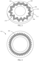
- the pleat guide channel 202 can include a repeating pattern of peaks and valleys distributed about a circumference of an end cap.
- an inner circumference 204 of the pleat guide channel 202 can include a first inner perimeter peak 206 extending away from a longitudinal axis of the end cap, and a first inner perimeter valley 208 extending toward a longitudinal axis of the end cap.
- the outer circumference 210 of the pleat guide channel 202 can include a first outer perimeter peak 212 extending toward a longitudinal axis of the end cap, and a first outer perimeter valley 214 extending away from a longitudinal axis of the end cap.
- the pleat guide channel includes a plurality of inner perimeter peaks, inner perimeter valleys, outer perimeter peaks, and outer perimeter valleys
- the inner perimeter peaks of the inner circumference can be configured to align with the outer perimeter valleys of the outer circumference
- the outer perimeter peaks of the outer circumference can be configured to align with the inner perimeter valleys of the inner circumference. It will be appreciated that this configuration of peaks and valleys provides that the inner circumference and the outer circumference of the pleat guide channel can assume the same profile as each other.
- the repeating pattern of peaks and valleys in FIGS. 2 and 3 are shown as sharp, angular structures, the shape of these peaks and valleys can also include a rounded shape, a square shape, a trapezoidal shape, combinations thereof, and the like.
- the repeating pattern can include a repeating pattern of uniformly distributed peaks and valleys about a circumference of an end cap.
- the repeating pattern can include a repeating pattern of non-uniformly distributed peaks and valleys about a circumference of an end cap.
- Pleat guide channel 202 can be configured to receive a curable resin (not shown), such as a polyurethane resin, to act as a glue to affix a pleated filter media within the pleat guide channel of an end cap.
- a curable resin such as a polyurethane resin
- the bottom of the pleat guide channel can be flat, while in other embodiments the bottom of the pleat guide channel can be rounded, triangular, and the like.
- the pleat guide channel can include a uniform pattern about the circumference of the end cap. In other embodiments, the pleat guide channel can include a non-uniform pattern about the circumference of the end cap. In some embodiments the end cap includes only one pleat guide channel, while in other embodiments the end can include more than one pleat guide channel. In other embodiments, the pleat guide channel can include be included to accommodate a pleated filter media that includes a variable pleat height design.
- the depth of the pleat guide channel can include depths of from 0.635 cm (0.25 inches) to from 1.27 cm (0.5 inches). In various embodiments, the depth of the pleat guide channel can include depths of from 0.3175 cm (0.125 inches) to 2.54 cm (1.0 inches). In some embodiments, the pleat guide channel can include those having depths of from 0.3175 cm (0.125 inches), 0.635 cm (0.25 inches), 0.9525 cm (0.375 inches), 1.27 cm (0.5 inches).
- the pleat guide channel comprises a uniform pleat channel depth. In other embodiments, the pleat guide channel comprises a non-uniform pleat channel depth.
- the width of the pleat guide channel can include widths of from about 15% to 35% greater than the width of a pleated filter media to be placed into the pleat guide channel. In some embodiments, the width of the pleat guide channel can include those having a width of from 20% to 30% greater than the width of a pleated filter media to be placed into the pleat guide channel. In various embodiments, the width of the pleat guide channel can be from 10%, 15%, 20%, 25%, 30%, or 35% greater than the width of a pleated filter media to be placed into the pleat guide channel, or any percentage falling within a range wherein any of the forgoing percentages can serve as the lower or upper bound of the range, provided that the lower bound of the range is a value less than the upper bound of the range.
- the diameter of the end cap can include those having a diameter of 2.54 cm (1 inch), 5.08 cm (2 inches), 7.62 cm (3 inches), 10.16 cm (4 inches), 12.7 cm (5 inches), 15.24 cm (6 inches), 17.78 cm (7 inches), 20.32 cm (8 inches), 22.86 cm (9 inches), or 25.4 cm (10 inches), or any diameter falling within a range wherein any of the forgoing diameters can serve as the lower or upper bound of the range, provided that the lower bound of the range is a value less than the upper bound of the range.
- the diameter of the end cap can include those having a diameter of greater than 25.4 cm (10 inches).
- the peaks and valleys can include configurations where each peak and valley can accept more than one pleat of a pleated filter media.
- a single peak or valley disposed along the inner or outer perimeter can accept 1, 2, or 3 pleats from a pleated filter media, or various combinations thereof.
- each single peak or valley can accept more than 3 pleats, such that the stability of the pleats is maintained.
- some of the peaks and valleys described in reference to the end caps will be skipped such that they do not include a pleat from a pleated filter media.
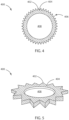
- FIGS. 4 and 5 a schematic top plan view and a schematic perspective view, respectively, of an interior pleat guide 400 is shown in accordance with various embodiments herein.
- the interior pleat guide 400 can include a repeating pattern of peaks and valleys distributed about the outer circumference 406 of the interior pleat guide 400.
- the outer circumference 406 can include a first guide peak 402 extending away from a center point of the interior pleat guide 400, and a first guide valley 404 extending toward a center point of the interior pleat guide 400.
- the guide peaks along the outer circumference of the interior pleat guide 400 can be configured to align with the filter media valleys of a corresponding pleated filter media, and the guide valleys along the outer circumference of the interior pleat guide 400 can be configured to align with the filter media peaks of a corresponding pleated filter media, thus providing spacing between the pleats of the filter media to keep the pleats apart from each other. Such a configuration prevents blinding of various surfaces of the pleated media filter.
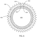
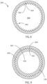
- FIG. 6 a schematic top plan view an interior pleat guide 400 placed in structural contact with an interior surface of a pleated filter media 108 is shown in accordance with various embodiments herein.
- the guide peaks 402 of the outer circumference of the interior pleat guide 400 can be configured to align with the filter media valleys of an inner circumference of a pleated filter media 108
- the guide valleys 404 of the outer circumference of the interior pleat guide 400 can be configured to align with the filter media peaks 602 of the inner circumference of the pleated filter media 108.
- the alignment of peaks and valleys allows the peaks and valleys on the interior pleat guide to interface with the pleated filter media to maintain pleat spacing between corresponding pleats of the pleated filter media.
- spacing control can be maintained between the pleats of the filter media to keep the pleats apart from each other during manufacture, storage, and operation.
- the interior pleat guide can include spacing regions between neighboring peaks and valleys that are equivalent to the width of a pleat of a pleated filter media but do not provide supportive contact thereto.
- the interior pleat guides herein can be configured to skip every n th pleat of a pleated filter media, where n can be 1, 2, 3, 4, 5, 6, 7, 8, 9, 10, or more.
- One or more interior pleat guides can be placed along an interior length of a pleated filter media to provide structural support to the pleats to keep them separated during manufacture, storage and operation.
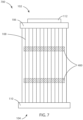
- FIG. 7 a schematic side plan view shows two interior pleat guides 400 placed in structural contact within an interior of a pleated filter media 108 is shown in accordance with various embodiments herein.
- the filter assembly 700 includes a first end 102 and a second end 104, including a first end cap 106 disposed at the first end 102 and a second end cap 110 disposed at the second end 104.
- Filter assembly 700 Disposed between the first end cap 106 and the second end cap 110 is a pleated filter media 108, where pleated filter media 108 includes a plurality of repeating pleats about a circumference of the pleated filter media.
- Filter assembly 700 further includes a sealable mounting element 112 at the first end 102.
- Filter assembly 700 includes two interior pleat guides 400 disposed along the length of the pleated filter media 108. While only two interior pleat guides are shown in FIG. 7 , it will be appreciated that one or more interior pleat guides can be included in the filter assemblies as contemplated herein. In some embodiments, 1, 2, 3, 4, 5, 6, 7, 8, 9, or 10 interior pleat guides can be included along a length of the pleated filter media of the filter assembly. In some embodiments, the filter assemblies described herein can include any number of interior pleat guides falling within a range wherein any of the forgoing numbers of interior pleat guides can serve as the lower or upper bound of the range, provided that the lower bound of the range is a value less than the upper bound of the range.
- one or more interior pleat guides can be connected with struts or other connection means along a length of a pleated filter media to create a cage-like configuration of interior pleat guides. Any number of the interior pleat guides can be attached to the pleated filter media using a glue, heat, or other method of fixation.
- FIG. 8 a schematic top plan view of an exterior pleat guide 800 is shown in accordance with various embodiments herein.
- the exterior pleat guide 800 can include a repeating pattern of peaks and valleys distributed about the inner circumference 806 of the exterior pleat guide 800.
- the inner circumference 806 can include a first guide peak 802 extending toward a center point of the exterior pleat guide 800, and a first guide valley 804 extending away from a center point of the exterior pleat guide 800.
- the exterior pleat guide 800 of FIG. 8 includes a center aperture 808 defined by an interior circumference of the interior pleat guide.
- the center aperture 808 can accommodate the filter media therethrough.
- FIG. 9 a schematic top plan view of an exterior pleat guide 800 placed in structural contact with the exterior surface of a pleated filter media 108 is shown in accordance with various embodiments herein.
- the guide peaks 802 along the outer circumference of the exterior pleat guide 800 can be configured to align with the filter media valleys 604 of an outer circumference of a pleated filter media 108
- the guide valleys 804 along the outer circumference of the exterior pleat guide 800 can be configured to align with the filter media peaks 602 of the outer circumference of the pleated filter media 108.
- peaks and valleys allow the peaks and valleys on the exterior pleat guide to interface with the pleated filter media to maintain pleat spacing between corresponding pleats of the pleated filter media.
- spacing control can be maintained between the pleats of the filter media to keep the pleats apart from each other during manufacture, storage, and operation.
- One or more exterior pleat guides can be placed along an exterior length of a pleated filter media to provide structural support to the pleats to keep them separated during manufacture, storage, and operation.
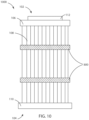
- FIG. 10 a schematic side plan view of two exterior pleat guides 800 placed in structural contact within an exterior of a pleated filter media 108 is shown in accordance with various embodiments herein.
- the filter assembly 1000 includes a first end 102 and a second end 104, including a first end cap 106 disposed at the first end 102 and a second end cap 110 disposed at the second end 104.
- Filter assembly 700 Disposed between the first end cap 106 and the second end cap 110 is a pleated filter media 108, where pleated filter media 108 includes a plurality of repeating pleats about a circumference of the pleated filter media.
- Filter assembly 700 further includes a sealable mounting element 112 at the first end 102.
- Filter assembly 1000 includes two exterior pleat guides 800 disposed along the length of the pleated filter media 108. While only two exterior pleat guides are shown in FIG. 10 , it will be appreciated that one or more exterior pleat guides can be included in the filter assemblies as contemplated herein. In some embodiments, 1, 2, 3, 4, 5, 6, 7, 8, 9, or 10 exterior pleat guides can be included along a length of the pleated filter media of the filter assembly. In some embodiments, the filter assemblies described herein can include any number of exterior pleat guides falling within a range wherein any of the forgoing numbers of exterior pleat guides can serve as the lower or upper bound of the range, provided that the lower bound of the range is a value less than the upper bound of the range.
- one or more exterior pleat guides can be connected with struts or other connection means along a length of a pleated filter media to create a cage-like configuration of exterior pleat guides. Any number of the exterior pleat guides can be attached to the pleated filter media using a glue, heat, or other method of fixation.
- the filter assemblies as described herein can utilize any combination of the end caps having pleat guide channels disposed therein, the interior pleat guides, and the exterior pleat guides, as described herein.
- Both interior pleat guides and exterior pleat guides described herein can include those having guide peaks and guide valleys of varying depths.
- the guide peaks can include those that have a length of from 0.635 cm (0.25 inches) to 1.27 cm (0.5 inches).
- the guide peaks can include those that have a length from 0.3175 cm (0.125 inches) to 2.54 cm (1.0 inches).
- the guide peaks can include those that have a length of 0.3175 cm (0.125 inches), 0.635 cm (0.25 inches), 0.9525 cm (0.375 inches), 1.27 cm (0.5 inches).
- the guide valleys can include those that have a depth of from 0.635 cm (0.25 inches) to 1.27 cm (0.5 inches). In some embodiments, the guide valleys can include those that have depths from 0.3175 cm (0.125 inches) to 2.54 cm (1.0 inches). In some embodiments, the guide valleys can include those that have depth of 0.3175 cm (0.125 inches), 0.635 cm (0.25 inches), 0.9525 cm (0.375 inches), 1.27 cm (0.5 inches).
- the thickness of both interior pleat guides and exterior pleat guides described herein can include those that have a thickness of from 1 millimeter (mm) to 10 mm.
- the thickness of the pleat guides herein can include those having a thickness of from 3 mm to 5 mm thick.
- the thickness of the pleat guides herein can include those having a thickness of 1, 2, 3, 4, 5, 6, 7, 8, 9, or 10 mm, or any thickness falling within a range wherein any of the forgoing thicknesses can serve as the lower or upper bound of the range, provided that the lower bound of the range is a value less than the upper bound of the range.
- the thickness of the end cap can include those having a diameter of greater than 25.4 cm (10 inches).
- the interior pleat guides can further include various configurations as discussed in reference to FIGS. 11-13 .
- FIGS. 11-13 schematic top plan views of various pleat guides are shown in accordance with various embodiments herein.
- the interior pleat guide 1100 shown in FIG. 11 does not include a central aperture.
- Interior pleat guide 1100 can be formed from a material that includes a honeycomb pattern of pores ranging in size such that the porous interior pleat guide can allow for the passage of a fluid therethrough.
- the interior pleat guide 1200 shown in FIG. 12 includes a square-shaped central aperture 1202 defined by an inner circumference of the interior pleat guide 1200.
- FIG. 13 includes a central aperture having four aperture portions 1302, 1304, 1306, and 1308 that are each defined by the body of the interior pleat guide 1300. While the central apertures of FIGS. 12 and 13 are shown to include a square shape or four pie-slice shapes, it will be appreciated that any shape can be utilized to provide a central passageway for the passage of a fluid or other filter assembly component, such as a core structure. Many of these shapes, especially those with multiple aperture portions, also include struts and supports that enhance the structural integrity of the pleat guide.
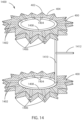
- the plurality of central apertures 1404 can be connected to a hollow central coupling ring 1408 disposed at the center of each of the interior pleat guides 400.
- the hollow central coupling ring 1408 can be an integral component of the interior pleat guide 400 or it can be a separate component to the interior pleat guides 400.
- Each central coupling ring 1408 can be connected by a longitudinal hollow tube 1410. Longitudinal hollow tube 1410 can be further coupled to a compressed air inlet port 1412.
- the interior pleat guides 400 with hollow passages 1402, the hollow central coupling ring 1408, the longitudinal hollow tube 1410, and the compressed air inlet port 1412 can form back-pulsing assembly 1400.
- the back-pulsing assembly 1400 can be placed within an interior of a pleated filter media to provide structural support to the pleats of a pleated filter media to keep them separated during manufacture, storage, and operation. While the back-pulsing assembly 1400 shown in FIG. 14 only includes two pleat guides 400, it will be appreciated that more than two pleat guides can be used in the back-pulsing assembly 1400. In some embodiments, the number of pleat guides used in the back-pulsing assembly 1400 can be greater than or equal to two, three, four, five, six, or seven pleat guides.
- the pleat guides can include those having various scaffold configurations and can be placed within an interior volume of or around an exterior of a pleated filter media to provide structural support to the pleats of a pleated filter media to keep them separated during manufacture, storage, and operation.
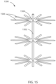
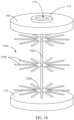
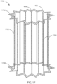
- FIGS. 15-18 schematic perspective views of various pleat guides having a scaffold configuration are shown in accordance with various embodiments herein.
- the scaffold pleat guide 1500 shown in FIG. 15 can include a central longitudinal axle portion 1502.
- Central longitudinal axle portion 1502 can be connected to one or more spoke wheels 1504.
- a first spoke wheel 1504 is spaced apart axially from a second spoke wheel 1504.
- the central longitudinal axle portion 1502 connects the first spoke wheel to the second spoke wheel and maintains the axial spacing between the two spoke wheels.
- Each spoke wheel 1504 can include a plurality of spokes 1506 extending in a radial direction outward from the central longitudinal axle portion 1502.
- the spoke wheels 1504 can include a plurality of spokes 1506 such that there is one spoke 1506 per pleat in the filter medium it is configured to support.
- the spoke wheels 1504 can include a plurality of spokes 1506 such that it can be configured to skip or support every n th pleat of a pleated filter media, where n can be 1, 2, 3, 4, 5, 6, 7, 8, 9, 10, or more.
- Scaffold pleat guide 1500 is shown in FIG. 15 as a stand-alone structure not connected to any other components.
- scaffold pleat guide 1500 can be incorporated as an integral unit with the first end cap 106 and second end cap 110, as shown in FIG. 16 .
- the scaffold pleat guide 1500 can be a single unitary component with the first end cap 106 and the second end cap 110, or it can be a separate component configured to connect to the first end cap 106 and the second end cap 110.
- the scaffold pleat guide 1700 shown in FIG. 17 includes a configuration having an exterior wire frame 1702 that can be disposed about the exterior of a filter media.
- the exterior wire frame 1702 can include one or more axial frames 1706 configured to be shaped complementary to a filter media to be disposed within the center of the scaffold pleat guide 1700.
- the exterior wire frame 1702 can include a plurality of longitudinal rods 1704 extending between valleys 404 on each of the axial frames 1706.
- the longitudinal rods 1704 maintain axial spacing between two axial frames.
- the number of axial frames 1706 used in the scaffold pleat guide 1700 can be greater than or equal to two, three, four, five, six, or seven axial frames 1706.
- the axial frame 1706 can include a plurality of guide peaks 402 and guide valleys 404 as described elsewhere herein, where that there can be one guide peak 402 per pleat in the filter medium it is configured to support. It will be appreciated that in some embodiments, the axial frame 1706 can include a plurality of guide peaks 402 such that it can be configured to support or skip every n th pleat of a pleated filter media, where n can be 1, 2, 3, 4, 5, 6, 7, 8, 9, 10, or more.
- the scaffold pleat guide 1800 shown in FIG. 18 includes a configuration having an interior wire frame 1802 that can be disposed within the interior of a filter media having a corresponding shape.
- the interior wire frame 1802 includes a plurality of longitudinal rods 1804 that are configured to be disposed within the pleat peaks of a filter media.
- the interior wire frame 1802 can further include a first axial frame 1805 including one or more axial struts 1806, and a second axial frame 1808 including one or more axial struts 1806.
- Each axial frame 1805, 1808 can include a plurality of guide peaks 402 and guide valleys 404 as described elsewhere herein, so that there can be one guide peak 402 per pleat in the filter medium it is configured to support.
- each axial frame can include a plurality of guide peaks 402 such that it can be configured to support or skip every n th pleat of a pleated filter media, where n can be 1, 2, 3, 4, 5, 6, 7, 8, 9, 10, or more.
- the end caps and pleat guide structures described herein can be formed using the process of additive manufacturing, referred to herein as 3-dimensional (3D) printing.
- the end caps and pleat guide structures generated using 3D printing can include unique and fine structural detail, including those having a high aspect ratio.
- the fine features incorporated into the end caps and pleat guides can include, but is not to be limited to, a honeycomb pore structure having a varying distribution of varying pore sizes, a honeycomb pore structure having a uniform distribution of uniform pores sizes, fine struts, fine mesh structures, a gradient pore structures throughout the material, threads, ridges, micro-surfaced to confer roughness and additional surface area, open cavities, central apertures, and the like.
- the pleat guides can be 3D printed to include guide peaks and valleys that are highly porous to allow for the transfer of a fluid at the pleat guide/pleated filter media interface.
- the 3D printing process can mix various materials to generate the end caps and pleat guides.
- thermoplastic polymers including, but not to be limited to polyamides, polypropylene, polyurethane, polyethylene, polylactic acid, acrylonitrile butadiene styrene, styrene, and copolymers, mixtures, or derivatives thereof.
- the pleat guides herein can be constructed of a variety of materials that can withstand a range of pressures, temperatures, and chemical conditions in the environments in which they are used in operation.
- the pleat guides should further be constructed of materials that are at least as strong as the filter media that they are designed to support.
- end caps and pleat guides described herein can be made by injection molding manufacturing methods. Examples of procedures for forming end caps and pleat guides by injection molding manufacturing methods are known in the art.
- the open area can fall within a range of 50 % to 85 %, or 52 % to 83 %, or 55 % to 81 %, or 58 % to 79 %, or 60 % to 78 %, or 62 % to 76 %, or 65 % to 74 %, or 68 % to 72 %, or can be about 70 %.
- porosity can also be accomplished is by choosing material for the structure that is itself porous or can be modified after printing to be porous.
- Some 3D printing materials incorporate particles, such as spheres, of thermoplastic material of a different type than the remainder of the material. These particles can be partially cured and dissolved out of the structure after printing.
- Another option is to selectively bake or etch away particles that are included in the materials of the structure. These processes result in void spaces within the printed materials, increasing the porosity of the material.
- pore size refers to spaces formed by materials within a printed structure.
- the pore size of the media can be and estimated by reviewing electron photographs of the media.
- the average pore size of a media can also be calculated using a Capillary Flow Porometer having model no. APP 1200 AEXSC available from Porous Materials Inc. of Ithaca, NY.
- the average pore size for the printed material can be greater than or equal to 0.3 nanometers, 0.6 nanometers, 0.9 nanometers, 1.2 nanometers, or 1.5 nanometers. In some embodiments, the average pore size can be less than or equal to 3.0 nanometers, 2.6 nanometers, 2.2 nanometers, 1.9 nanometers, or 1.5 nanometers. In some embodiments, the average pore size can fall within a range of 0.3 nanometers to 3.0 nanometers, or 0.6 nanometers to 2.6 nanometers, or 0.9 nanometers to 2.2 nanometers, or 1.2 nanometers to 1.9 nanometers, or can be about 1.5 nanometers.
- the average pore size can be greater than or equal to 0.01 micrometers, 0.02 micrometers, 0.03 micrometers, 0.04 micrometers, or 0.05 micrometers, or can be an amount falling within a range between any of the foregoing.
- the average pore size of the printed material can be greater than or equal to 15 microns, 17 microns, 18 microns, or 20 microns. In some embodiments, the average pore size can be less than or equal to 25 microns, 23 microns, 22 microns, or 20 microns. In some embodiments, the average pore size can fall within a range of 15 microns to 25 microns, or 17 microns to 23 microns, or 18 microns to 22 microns, or can be about 20 microns.
- the average pore size can fall within a range of 0.5 mm to 2.0 mm, or 0.6 mm to 1.8 mm, or 0.7 mm to 1.6 mm, or 0.8 mm to 1.4 mm, or 0.9 mm to 1.2 mm, or can be about 1.0 mm.
- pore size refers to spaces formed by materials within a printed structure.
- the pore size of the media can be and estimated by reviewing electron photographs of the media.
- the average pore size of a media can also be calculated using a Capillary Flow Porometer having model no. APP 1200 AEXSC available from Porous Materials Inc. of Ithaca, NY.
- the phrase “configured” describes a system, apparatus, or other structure that is constructed or configured to perform a particular task or adopt a particular configuration.
- the phrase “configured” can be used interchangeably with other similar phrases such as arranged and configured, constructed and arranged, constructed, manufactured and arranged, and the like.
Landscapes
- Chemical & Material Sciences (AREA)
- Chemical Kinetics & Catalysis (AREA)
- Physics & Mathematics (AREA)
- Geometry (AREA)
- Filtering Of Dispersed Particles In Gases (AREA)
- Filtering Materials (AREA)
Claims (15)
- Composant d'ensemble de filtre, comprenant:un guide de plis (400) comprenant un motif répétitif comprenant une pluralité de sommets (402) et une pluralité de creux (404) répartis sur la circonférence du guide de plis (400);la pluralité de sommets (402) et la pluralité de creux (404) étant configurés pour s'interfacer avec un matériau filtrant plissé (108) afin de maintenir l'espacement entre plis entre les plis correspondants du matériau filtrante plissée (108);caractérisé en ce que le guide de plis (400) définit une pluralité de passages creux (1402) qui s'étendent depuis une portion centrale du guide de plis (400) à une surface circonférentielle du guide de plis, chaque passage creux (1402) se connectant à une ouverture centrale (1404) au niveau de la portion centrale et se connectant à une ouverture circonférentielle extérieure (1406) au niveau de la surface circonférentielle du guide de plis, la pluralité d'ouvertures centrales (1404) étant connectées à un anneau de couplage central (1408) creux disposé au niveau du centre de chacun des guides de plis intérieurs (400),le guide de plis (400) définissant en outre un orifice d'entrée de fluide (1412) en communication fluidique avec la pluralité de passages creux (1402),et chaque anneau de couplage central (1408) étant relié par un tube creux longitudinal (1410) qui est en outre couplé à l'orifice d'entrée de fluide (1412).
- Composant d'ensemble de filtre selon la revendication 1, le guide de plis comprenant un guide de plis intérieur (400).
- Composant d'ensemble de filtre selon l'une des revendications 1 et 2, la pluralité de sommets s'étendant à l'écart d'un point central du guide de plis de 0,635 cm (0,25 pouce) à 1,27 cm (0,5 pouce).
- Composant d'ensemble de filtre selon l'une des revendications 1 à 3, le guide de plis ayant une épaisseur de 3 mm à 5 mm.
- Composant d'ensemble de filtre selon l'une des revendications 1 à 4, le guide de plis ayant un diamètre compris entre 7,62 cm (3 pouces) et 12,7 cm (5 pouces).
- Composant d'ensemble de filtre selon l'une des revendications 1 à 5, le guide de plis comprenant une ouverture centrale (408).
- Composant d'ensemble de filtre selon les revendications 1 à 6, comprenant: un capuchon d'extrémité (106, 110) comprenant un canal de guide de plis (202) disposé autour d'une circonférence du capuchon d'extrémité (106, 110), le canal de guide de plis (202) comprenant un motif répétitif comprenant une pluralité de sommets et une pluralité de creux réparties autour de la circonférence du capuchon d'extrémité (106, 110); et le canal de guide de plis (202) étant configuré pour recevoir et supporter mécaniquement un matériau filtrant plissé (108) à l'intérieur du canal de guide de plis (202).
- Composant d'ensemble de filtre selon la revendication 7, le canal de guide de plis (202) comprenant une profondeur de canal de plis uniforme.
- Composant d'ensemble de filtre selon l'une des revendications 7 à 8, le canal de guide de plis (202) comprenant une profondeur de canal de plis non uniforme.
- Composant d'ensemble de filtre selon l'une des revendications 7 à 9, le canal de guide de plis (202) comprenant une profondeur de 0,3175 cm (0,125 pouce) à 2,54 cm (1,0 pouce).
- Composant d'ensemble de filtre selon l'une des revendications 7 à 10, le canal de guide de plis (202) comprenant une épaisseur qui est de 20 % à 30 % supérieure à l'épaisseur d'un matériau filtrant plissé (108) à placer dans le canal de guide de plis (202).
- Composant d'ensemble de filtre selon l'une des revendications 7 à 11, le canal de guide de plis (202) comprenant une épaisseur qui est de 25 % supérieure à l'épaisseur d'un matériau filtrant plissé (108) à placer dans le canal de guide de plis (202).
- Composant d'ensemble de filtre selon l'une des revendications 7 à 12, le capuchon d'extrémité (106, 110) ayant un diamètre de 76,2 mm (3 pouces) à 127 mm (5 pouces).
- Composant d'ensemble de filtre selon l'une des revendications 7 à 13, le motif répétitif comprenant un motif répétitif de sommets et de creux uniformément répartis sur la circonférence du capuchon d'extrémité (106, 110).
- Composant d'ensemble de filtre selon l'une des revendications 7 à 14, le motif répétitif comprenant un motif répétitif de sommets et de creux non uniformément répartis sur la circonférence du capuchon d'extrémité (106, 110).
Applications Claiming Priority (2)
| Application Number | Priority Date | Filing Date | Title |
|---|---|---|---|
| US202063127066P | 2020-12-17 | 2020-12-17 | |
| PCT/US2021/064017 WO2022133204A1 (fr) | 2020-12-17 | 2021-12-17 | Bouchons d'extrémité et guides de plis pour filtration |
Publications (2)
| Publication Number | Publication Date |
|---|---|
| EP4263016A1 EP4263016A1 (fr) | 2023-10-25 |
| EP4263016B1 true EP4263016B1 (fr) | 2025-06-25 |
Family
ID=79830990
Family Applications (1)
| Application Number | Title | Priority Date | Filing Date |
|---|---|---|---|
| EP21847578.8A Active EP4263016B1 (fr) | 2020-12-17 | 2021-12-17 | Bouchons d'extrémité et guides de plis pour filtration |
Country Status (4)
| Country | Link |
|---|---|
| US (1) | US20240001279A1 (fr) |
| EP (1) | EP4263016B1 (fr) |
| CN (1) | CN116829239A (fr) |
| WO (1) | WO2022133204A1 (fr) |
Citations (1)
| Publication number | Priority date | Publication date | Assignee | Title |
|---|---|---|---|---|
| GB1056263A (en) * | 1962-10-02 | 1967-01-25 | Pierre Lucien Theobald | Filtration units |
Family Cites Families (11)
| Publication number | Priority date | Publication date | Assignee | Title |
|---|---|---|---|---|
| US4878930A (en) * | 1984-03-15 | 1989-11-07 | W. L. Gore & Associates, Inc. | Filter cartridge |
| JPH0332910U (fr) * | 1989-08-01 | 1991-03-29 | ||
| GB9425350D0 (en) * | 1994-12-15 | 1995-02-15 | Numatic Int Ltd | Improved filter |
| US5531892A (en) * | 1995-09-15 | 1996-07-02 | Minnesota Mining And Manufacturing Company | Zigzag filter media and frame having triangular pleat stabilizing elements |
| US6955701B2 (en) * | 2002-03-28 | 2005-10-18 | Donaldson Company, Inc. | Filter element and use thereof; methods of manufacture |
| US7147625B2 (en) * | 2003-07-01 | 2006-12-12 | Icet, Inc. | Leg bag accessory |
| GB2413510B (en) * | 2004-04-27 | 2006-07-12 | Read Yes Entpr Co Ltd | Improved structure of filtering bag combination |
| US20130195740A1 (en) * | 2012-01-31 | 2013-08-01 | Shulong Li | Filter for removal of heavy metals |
| WO2015010085A2 (fr) * | 2013-07-19 | 2015-01-22 | Donaldson Company, Inc. | Élément filtrant, filtre à air, et procédés |
| CN208177111U (zh) * | 2018-02-05 | 2018-12-04 | 陕西五洲钒金属材料科技有限公司 | 除尘骨架结构 |
| WO2020243080A1 (fr) * | 2019-05-29 | 2020-12-03 | Donaldson Company, Inc. | Cœur incurvé pour filtre à plis variables |
-
2021
- 2021-12-17 EP EP21847578.8A patent/EP4263016B1/fr active Active
- 2021-12-17 WO PCT/US2021/064017 patent/WO2022133204A1/fr not_active Ceased
- 2021-12-17 CN CN202180084986.3A patent/CN116829239A/zh active Pending
- 2021-12-17 US US18/039,121 patent/US20240001279A1/en not_active Abandoned
Patent Citations (1)
| Publication number | Priority date | Publication date | Assignee | Title |
|---|---|---|---|---|
| GB1056263A (en) * | 1962-10-02 | 1967-01-25 | Pierre Lucien Theobald | Filtration units |
Also Published As
| Publication number | Publication date |
|---|---|
| WO2022133204A1 (fr) | 2022-06-23 |
| CN116829239A (zh) | 2023-09-29 |
| US20240001279A1 (en) | 2024-01-04 |
| EP4263016A1 (fr) | 2023-10-25 |
Similar Documents
| Publication | Publication Date | Title |
|---|---|---|
| EP1554028B1 (fr) | Element de filtre comprenant un milieu de filtration et un support plisse a couches multiples | |
| CA2886303C (fr) | Elements de filtre et methodes de filtrage de liquides | |
| EP2969117B1 (fr) | Cartouches de filtre tubulaires ovoïdes et systèmes de filtre les utilisant | |
| EP4438151A2 (fr) | Élément filtrant doté de saillies | |
| US20120211408A1 (en) | Extended Area Filter With Internal Support Structures | |
| EP3331618A1 (fr) | Cartouche pour masque de protection respiratoire et masque de protection respiratoire | |
| JP2018023979A (ja) | フィルターエレメント | |
| US10799815B2 (en) | High pressure resistant filter | |
| US6910589B1 (en) | Annular pleated filter cartridge for liquid filtration apparatus | |
| US20100206810A1 (en) | Fluid treatment elements and fluid treatment arrangements with spaces between fluid treatment elements and methods for making and using them | |
| US20240001279A1 (en) | End caps and pleat guides for filtration | |
| US8911633B2 (en) | Fluid treatment elements and fluid treatment arrangements with posts and/or bands between fluid treatment elements and methods for making and using them | |
| EP4263221A1 (fr) | Structures imprimées pour supporter des fibres électrofilées pour filtration | |
| TWI878987B (zh) | 包括具有混合褶皺高度的過濾元件的圓柱形多孔過濾器及處理流體之方法 | |
| WO2025059559A1 (fr) | Cartouche de filtre | |
| JP3688477B2 (ja) | 筒状フィルタ部材及びその製造方法並びに筒状フィルタ | |
| US20100206819A1 (en) | Fluid treatment elements and fluid treatment arrangements with fluid treatment elements having uneven surfaces and methods for making and using them | |
| JPH07265612A (ja) | 内燃機関のオイルフィルタ |
Legal Events
| Date | Code | Title | Description |
|---|---|---|---|
| STAA | Information on the status of an ep patent application or granted ep patent |
Free format text: STATUS: UNKNOWN |
|
| STAA | Information on the status of an ep patent application or granted ep patent |
Free format text: STATUS: THE INTERNATIONAL PUBLICATION HAS BEEN MADE |
|
| PUAI | Public reference made under article 153(3) epc to a published international application that has entered the european phase |
Free format text: ORIGINAL CODE: 0009012 |
|
| STAA | Information on the status of an ep patent application or granted ep patent |
Free format text: STATUS: REQUEST FOR EXAMINATION WAS MADE |
|
| 17P | Request for examination filed |
Effective date: 20230717 |
|
| AK | Designated contracting states |
Kind code of ref document: A1 Designated state(s): AL AT BE BG CH CY CZ DE DK EE ES FI FR GB GR HR HU IE IS IT LI LT LU LV MC MK MT NL NO PL PT RO RS SE SI SK SM TR |
|
| DAV | Request for validation of the european patent (deleted) | ||
| DAX | Request for extension of the european patent (deleted) | ||
| STAA | Information on the status of an ep patent application or granted ep patent |
Free format text: STATUS: EXAMINATION IS IN PROGRESS |
|
| 17Q | First examination report despatched |
Effective date: 20240517 |
|
| GRAP | Despatch of communication of intention to grant a patent |
Free format text: ORIGINAL CODE: EPIDOSNIGR1 |
|
| STAA | Information on the status of an ep patent application or granted ep patent |
Free format text: STATUS: GRANT OF PATENT IS INTENDED |
|
| INTG | Intention to grant announced |
Effective date: 20250203 |
|
| GRAS | Grant fee paid |
Free format text: ORIGINAL CODE: EPIDOSNIGR3 |
|
| GRAA | (expected) grant |
Free format text: ORIGINAL CODE: 0009210 |
|
| STAA | Information on the status of an ep patent application or granted ep patent |
Free format text: STATUS: THE PATENT HAS BEEN GRANTED |
|
| AK | Designated contracting states |
Kind code of ref document: B1 Designated state(s): AL AT BE BG CH CY CZ DE DK EE ES FI FR GB GR HR HU IE IS IT LI LT LU LV MC MK MT NL NO PL PT RO RS SE SI SK SM TR |
|
| REG | Reference to a national code |
Ref country code: GB Ref legal event code: FG4D |
|
| REG | Reference to a national code |
Ref country code: CH Ref legal event code: EP |
|
| REG | Reference to a national code |
Ref country code: CH Ref legal event code: EP |
|
| REG | Reference to a national code |
Ref country code: IE Ref legal event code: FG4D |
|
| REG | Reference to a national code |
Ref country code: DE Ref legal event code: R096 Ref document number: 602021033038 Country of ref document: DE |
|
| P01 | Opt-out of the competence of the unified patent court (upc) registered |
Free format text: CASE NUMBER: APP_30742/2025 Effective date: 20250626 |
|
| PG25 | Lapsed in a contracting state [announced via postgrant information from national office to epo] |
Ref country code: FI Free format text: LAPSE BECAUSE OF FAILURE TO SUBMIT A TRANSLATION OF THE DESCRIPTION OR TO PAY THE FEE WITHIN THE PRESCRIBED TIME-LIMIT Effective date: 20250625 |
|
| REG | Reference to a national code |
Ref country code: LT Ref legal event code: MG9D |
|
| PG25 | Lapsed in a contracting state [announced via postgrant information from national office to epo] |
Ref country code: NO Free format text: LAPSE BECAUSE OF FAILURE TO SUBMIT A TRANSLATION OF THE DESCRIPTION OR TO PAY THE FEE WITHIN THE PRESCRIBED TIME-LIMIT Effective date: 20250925 Ref country code: GR Free format text: LAPSE BECAUSE OF FAILURE TO SUBMIT A TRANSLATION OF THE DESCRIPTION OR TO PAY THE FEE WITHIN THE PRESCRIBED TIME-LIMIT Effective date: 20250926 |
|
| PG25 | Lapsed in a contracting state [announced via postgrant information from national office to epo] |
Ref country code: BG Free format text: LAPSE BECAUSE OF FAILURE TO SUBMIT A TRANSLATION OF THE DESCRIPTION OR TO PAY THE FEE WITHIN THE PRESCRIBED TIME-LIMIT Effective date: 20250625 |
|
| PG25 | Lapsed in a contracting state [announced via postgrant information from national office to epo] |
Ref country code: HR Free format text: LAPSE BECAUSE OF FAILURE TO SUBMIT A TRANSLATION OF THE DESCRIPTION OR TO PAY THE FEE WITHIN THE PRESCRIBED TIME-LIMIT Effective date: 20250625 |
|
| PG25 | Lapsed in a contracting state [announced via postgrant information from national office to epo] |
Ref country code: RS Free format text: LAPSE BECAUSE OF FAILURE TO SUBMIT A TRANSLATION OF THE DESCRIPTION OR TO PAY THE FEE WITHIN THE PRESCRIBED TIME-LIMIT Effective date: 20250925 |
|
| PG25 | Lapsed in a contracting state [announced via postgrant information from national office to epo] |
Ref country code: LV Free format text: LAPSE BECAUSE OF FAILURE TO SUBMIT A TRANSLATION OF THE DESCRIPTION OR TO PAY THE FEE WITHIN THE PRESCRIBED TIME-LIMIT Effective date: 20250625 |
|
| REG | Reference to a national code |
Ref country code: NL Ref legal event code: MP Effective date: 20250625 |
|
| PG25 | Lapsed in a contracting state [announced via postgrant information from national office to epo] |
Ref country code: NL Free format text: LAPSE BECAUSE OF FAILURE TO SUBMIT A TRANSLATION OF THE DESCRIPTION OR TO PAY THE FEE WITHIN THE PRESCRIBED TIME-LIMIT Effective date: 20250625 |
|
| PG25 | Lapsed in a contracting state [announced via postgrant information from national office to epo] |
Ref country code: PT Free format text: LAPSE BECAUSE OF FAILURE TO SUBMIT A TRANSLATION OF THE DESCRIPTION OR TO PAY THE FEE WITHIN THE PRESCRIBED TIME-LIMIT Effective date: 20251027 |
|
| REG | Reference to a national code |
Ref country code: AT Ref legal event code: MK05 Ref document number: 1805906 Country of ref document: AT Kind code of ref document: T Effective date: 20250625 |
|
| PG25 | Lapsed in a contracting state [announced via postgrant information from national office to epo] |
Ref country code: IS Free format text: LAPSE BECAUSE OF FAILURE TO SUBMIT A TRANSLATION OF THE DESCRIPTION OR TO PAY THE FEE WITHIN THE PRESCRIBED TIME-LIMIT Effective date: 20251025 |
|
| PG25 | Lapsed in a contracting state [announced via postgrant information from national office to epo] |
Ref country code: AT Free format text: LAPSE BECAUSE OF FAILURE TO SUBMIT A TRANSLATION OF THE DESCRIPTION OR TO PAY THE FEE WITHIN THE PRESCRIBED TIME-LIMIT Effective date: 20250625 Ref country code: SM Free format text: LAPSE BECAUSE OF FAILURE TO SUBMIT A TRANSLATION OF THE DESCRIPTION OR TO PAY THE FEE WITHIN THE PRESCRIBED TIME-LIMIT Effective date: 20250625 |
|
| PG25 | Lapsed in a contracting state [announced via postgrant information from national office to epo] |
Ref country code: CZ Free format text: LAPSE BECAUSE OF FAILURE TO SUBMIT A TRANSLATION OF THE DESCRIPTION OR TO PAY THE FEE WITHIN THE PRESCRIBED TIME-LIMIT Effective date: 20250625 |
|
| PG25 | Lapsed in a contracting state [announced via postgrant information from national office to epo] |
Ref country code: PL Free format text: LAPSE BECAUSE OF FAILURE TO SUBMIT A TRANSLATION OF THE DESCRIPTION OR TO PAY THE FEE WITHIN THE PRESCRIBED TIME-LIMIT Effective date: 20250625 |
|
| PG25 | Lapsed in a contracting state [announced via postgrant information from national office to epo] |
Ref country code: EE Free format text: LAPSE BECAUSE OF FAILURE TO SUBMIT A TRANSLATION OF THE DESCRIPTION OR TO PAY THE FEE WITHIN THE PRESCRIBED TIME-LIMIT Effective date: 20250625 |
|
| PG25 | Lapsed in a contracting state [announced via postgrant information from national office to epo] |
Ref country code: SK Free format text: LAPSE BECAUSE OF FAILURE TO SUBMIT A TRANSLATION OF THE DESCRIPTION OR TO PAY THE FEE WITHIN THE PRESCRIBED TIME-LIMIT Effective date: 20250625 |
|
| PG25 | Lapsed in a contracting state [announced via postgrant information from national office to epo] |
Ref country code: ES Free format text: LAPSE BECAUSE OF FAILURE TO SUBMIT A TRANSLATION OF THE DESCRIPTION OR TO PAY THE FEE WITHIN THE PRESCRIBED TIME-LIMIT Effective date: 20250625 |
|
| PG25 | Lapsed in a contracting state [announced via postgrant information from national office to epo] |
Ref country code: RO Free format text: LAPSE BECAUSE OF FAILURE TO SUBMIT A TRANSLATION OF THE DESCRIPTION OR TO PAY THE FEE WITHIN THE PRESCRIBED TIME-LIMIT Effective date: 20250625 |
|
| REG | Reference to a national code |
Ref country code: DE Ref legal event code: R097 Ref document number: 602021033038 Country of ref document: DE |
|
| PG25 | Lapsed in a contracting state [announced via postgrant information from national office to epo] |
Ref country code: DK Free format text: LAPSE BECAUSE OF FAILURE TO SUBMIT A TRANSLATION OF THE DESCRIPTION OR TO PAY THE FEE WITHIN THE PRESCRIBED TIME-LIMIT Effective date: 20250625 |
|
| PG25 | Lapsed in a contracting state [announced via postgrant information from national office to epo] |
Ref country code: IT Free format text: LAPSE BECAUSE OF FAILURE TO SUBMIT A TRANSLATION OF THE DESCRIPTION OR TO PAY THE FEE WITHIN THE PRESCRIBED TIME-LIMIT Effective date: 20250625 |
|
| PLBE | No opposition filed within time limit |
Free format text: ORIGINAL CODE: 0009261 |
|
| STAA | Information on the status of an ep patent application or granted ep patent |
Free format text: STATUS: NO OPPOSITION FILED WITHIN TIME LIMIT |
|
| REG | Reference to a national code |
Ref country code: CH Ref legal event code: L10 Free format text: ST27 STATUS EVENT CODE: U-0-0-L10-L00 (AS PROVIDED BY THE NATIONAL OFFICE) Effective date: 20260507 |
|
| 26N | No opposition filed |
Effective date: 20260326 |
|
| PG25 | Lapsed in a contracting state [announced via postgrant information from national office to epo] |
Ref country code: LT Free format text: LAPSE BECAUSE OF FAILURE TO SUBMIT A TRANSLATION OF THE DESCRIPTION OR TO PAY THE FEE WITHIN THE PRESCRIBED TIME-LIMIT Effective date: 20250625 |
|
| PG25 | Lapsed in a contracting state [announced via postgrant information from national office to epo] |
Ref country code: MC Free format text: LAPSE BECAUSE OF FAILURE TO SUBMIT A TRANSLATION OF THE DESCRIPTION OR TO PAY THE FEE WITHIN THE PRESCRIBED TIME-LIMIT Effective date: 20250625 |
|
| REG | Reference to a national code |
Ref country code: CH Ref legal event code: H13 Free format text: ST27 STATUS EVENT CODE: U-0-0-H10-H13 (AS PROVIDED BY THE NATIONAL OFFICE) Effective date: 20260723 |
|
| PG25 | Lapsed in a contracting state [announced via postgrant information from national office to epo] |
Ref country code: SE Free format text: LAPSE BECAUSE OF FAILURE TO SUBMIT A TRANSLATION OF THE DESCRIPTION OR TO PAY THE FEE WITHIN THE PRESCRIBED TIME-LIMIT Effective date: 20250625 |