EP4263094B1 - Drehkopfbearbeitungseinheit - Google Patents
Drehkopfbearbeitungseinheit Download PDFInfo
- Publication number
- EP4263094B1 EP4263094B1 EP21854737.0A EP21854737A EP4263094B1 EP 4263094 B1 EP4263094 B1 EP 4263094B1 EP 21854737 A EP21854737 A EP 21854737A EP 4263094 B1 EP4263094 B1 EP 4263094B1
- Authority
- EP
- European Patent Office
- Prior art keywords
- control
- machining unit
- bush
- unit according
- rotor
- Prior art date
- Legal status (The legal status is an assumption and is not a legal conclusion. Google has not performed a legal analysis and makes no representation as to the accuracy of the status listed.)
- Active
Links
Images


Classifications
-
- B—PERFORMING OPERATIONS; TRANSPORTING
- B23—MACHINE TOOLS; METAL-WORKING NOT OTHERWISE PROVIDED FOR
- B23B—TURNING; BORING
- B23B3/00—General-purpose turning-machines or devices, e.g. centre lathes with feed rod and lead screw; Sets of turning-machines
- B23B3/22—Turning-machines or devices with rotary tool heads
- B23B3/26—Turning-machines or devices with rotary tool heads the tools of which perform a radial movement; Rotary tool heads thereof
-
- B—PERFORMING OPERATIONS; TRANSPORTING
- B23—MACHINE TOOLS; METAL-WORKING NOT OTHERWISE PROVIDED FOR
- B23B—TURNING; BORING
- B23B3/00—General-purpose turning-machines or devices, e.g. centre lathes with feed rod and lead screw; Sets of turning-machines
- B23B3/22—Turning-machines or devices with rotary tool heads
-
- B—PERFORMING OPERATIONS; TRANSPORTING
- B23—MACHINE TOOLS; METAL-WORKING NOT OTHERWISE PROVIDED FOR
- B23B—TURNING; BORING
- B23B29/00—Holders for non-rotary cutting tools; Boring bars or boring heads; Accessories for tool holders
- B23B29/24—Tool holders for a plurality of cutting tools, e.g. turrets
Definitions
- the present invention relates to a machining unit with a rotary head carrying at least two pivoting tools, for machining a non-rotating part centered on the axis of rotation of the rotary head, comprising a frame on which is mounted a rotor supported by means of two external bearings, said rotor being provided with an axial conduit and, coupled to rotational drive means, means for axially guiding said non-rotating part, these means being carried by bearings in the rotor and by the fixed support, means for holding and axially moving said non-rotating part, at least two tool supports, mounted in said rotary head so as to pivot about respective axes parallel to the axis of rotation, each support comprising a control lever arranged transversely, pivoting control means, cooperating with said lever and comprising a control element, which is movable in axial translation in the rotor and coupled to a translation control device, and pairs of support members arranged respectively on each control lever and on the corresponding control element, each pair of support members comprising a
- the machining head of this type described in European patent No. EP 0 869 858 comprises a tool spindle equipped with two coupled tools, the pair of tools being controlled by a digital axis.
- the advancement of the workpiece is achieved by two profiled discs gripping the workpiece, one being driven by the axis motor and the other carried by a shaft ensuring the clamping of the workpiece.
- the workpiece is clamped by a collet in the feed system.
- the diameter of the workpiece becomes smaller than about 1 to 1.5 mm, any resistance due to machining can cause buckling of the workpiece between the collet used for feed and the guide system called bush, knowing that the minimum distance between these two elements must correspond at least to the length of the workpiece.
- Feeding by rotating disc allows for a short and fixed distance between the feed system and the guide, which allows the machining of workpieces with a diameter of a few tenths of a millimeter.
- the present invention proposes a solution to this problem, by making it possible to produce in the same space as current machining heads, heads capable of carrying up to four selectable tools during the machining cycle, without requiring rotation to be stopped.
- the machining unit having the characteristics of claim 1 according to the invention, characterized in that it comprises a control sleeve mounted coaxially on said spindle, this sleeve being arranged to slide axially and to occupy a first advanced position, a second retracted position, this sleeve carrying at one of its ends a control surface of ellipsoidal shape, arranged to cooperate with the helical guide surfaces and to carry out the plunging of the tools, means for axially moving said control sleeve and a phase shift device arranged to bring said control sleeve into two, three or four predetermined angular positions around its axis.
- the phase shift system is implemented electronically. It consists of two separate drive motors, one for the rotor and the other for the control sleeve. Each motor is equipped with a system for measuring its angular position.
- a special feature of the digital control makes it possible to control the two motors so that their rotation is perfectly synchronous, but also so that it is possible during rotation to control an angular shift of one relative to the other.
- the choice of This solution allows for the complete elimination of a complex and expensive mechanical system and greatly simplifies construction. It is the result of a thorough examination of technical possibilities, as well as a forecast analysis of the costs of the various versions.
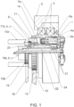
- the three-tool spindle consists of a rotor 1 carried by a pair of bearings 3, the whole being mounted in a casing 2.
- the rotational drive is provided by the toothed belt 13 meshing with the toothed pulley 12.
- a non-rotating tube 22 which is supported at one end in the fixed support 23 which also serves as a guide for the control rods 10a, 10b of the Figure 2A , and supported at the other end by a pair of precision bearings 21 housed in the rotor 1. It is inside this tube that the guide bushes 24 are slid, precisely adjusted to the diameter of the part to be machined.
- rotor In this rotor are mounted three tool holder axes 4a, 4b, 4c, all identical. On each end outside the spindle, a hexagon 4g, 4h, 4i allows the mounting of different cutting tool holders 5a, 5b and 5c.
- Each lever-shaped rear part 4j, 4k, 4l supports the propeller portion 4d, 4e, 4f which will be in contact with the control sleeve.
- Each axle is supported radially by two needle bearings 6a, 6b, 6c and 7a, 7b, 7c; the axial clearance is adjusted with elements 8a, 8b, 8c.
- the axial movement of the control rods 10a, 10b is transmitted to the spool 11.
- the pair of bearings 9 provides the connection between the non-rotating spool 11 and the rotating control sleeve 14, which slides on the tail of the rotor 1 and rotates with it.
- This sleeve has its own rotational drive via the belt 16 and the pulley 15.
- Three pins 17a, 17b, 17c are integral with the pulley 15 and the sleeve 14 and located at 120° to each other ( FIG 3B and 3C ).
- the rotor 1 In the rotor 1 are also provided three longitudinal grooves 18a, 18b, 18c, machined at 120°.
- the pins 17a, 17b, 17c will be opposite these grooves; it is then possible to advance the sleeve 14 via the control rods 10a and 10b, and thus to plunge one of the tools.
- the contact point 20 will come into contact with the helix portion 4d or 4e or 4f of the selected tool holder 1, 2, 3, and therefore cause a pivoting of the axis 4a, 4b, 4c and thus cause the selected tool to penetrate into the part to be machined.
- FIGS. 4A to 4D illustrate this functionality for tool holder 2.
- the Figure 4A shows in section the control sleeve 14 in the retracted position, which corresponds to a position clear of the tip of the tool 2 visible on the Figure 4B .
- socket 14 is fully advanced, and on the figure 4D , this position of the control sleeve 14 caused the tip of the tool 2 to move beyond the axis of the spindle, and therefore beyond the part to be machined.
- a spring 26a, 26b, 26c maintains the contact of the helix portion 4d, 4e, 4f with the point 20 of the sleeve, even in the event of the sleeve moving back.
- a boss 25a, 25b, 25c on the rotor 1 serves as a stop for each tool-holder axis 4a, 4b, 4c according to the Figure 5 . It thus limits the angular movement of the axes during the maximum retraction of the sleeve 14.
- This position also brings the pins 17a, 17b, 17c into a position corresponding to the groove 19.
- the sleeve 14 in the retracted position, can be rotated freely relative to the rotor 1. After having angularly positioned the sleeve 14 in such a way that the three pins 17a, 17b, 17c are located opposite the longitudinal grooves 18a, 18b, 18c, which corresponds to three possibilities all spaced 120° apart, it is possible to advance the sleeve 14 and therefore to plunge the selected tool.
- each of these three angular positions allows, by axially moving the sleeve 14, the point 20 to be brought into contact with the helix portion 4d or 4e or 4f of one of the three different tool holders. It thus makes it possible to plunge the chosen tool so that the tool selection is therefore carried out.
- FIGS. 6A and 6B illustrate the case of the first tool-holder axis whose tip is completely immersed. To do this, the contact point 20 was brought opposite the helix portion 4d of axis no. 1 and the sleeve 14 pushed forward. We see on the Figure 6B that the lever 4j is well detached from the stop 25a. On the other hand, we see that the other two axes are themselves resting on their respective stops 25b and 25c.
- FIGS 7A and 7B respectively 8A and 8B illustrate the cases of the second and third tool holders, with the tool tip in a position analogous to that of the Figure 6A .
- FIGs 7B And 8B the different angular positions of the contact point 20 in each case and the fact that only the controlled axis is detached from its stop.
- each of the belts 13 and 16 is driven by a separate motor, 27 respectively 29, each carrying a toothed pulley 28, respectively.
- the motor/spindle transmission ratio should preferably be an integer; in a particular case, the ratio chosen is equal to 1.
- Each motor has an electronic encoder measuring its angular position and providing a reference index once per revolution.
- the electronic control system (CNC) makes it possible to drive the two spindle elements in a perfectly synchronous manner, the motor 29 matching its angular position at all times to that of the motor 27. It also has instructions making it possible to command the motor 29 to shift its angular position by a defined value relative to that of the motor 27, and this while the spindle is working, that is to say with the two motors rotating.
- This feature thus makes it possible, during spindle rotation, to freely choose to work with one of the three tool holders 4a or 4b or 4c.
- the advantages provided by the machining unit according to the invention compared to the system of the prior art are as follows:
- the key point is the special arrangement of the 3 main bearings. This provides significant advantages in terms of rigidity and load capacity. It also allows for a specific lubrication point for the 3 bearings, which guarantees absolute control of the quantity of lubricant supplied, and therefore of the temperature and operating conditions of the spindle.
- This arrangement finally makes it possible to simply bring cutting oil through the guide barrel to the tools, without having to pass through the curtain formed by the rotating tools passing in front of the jet.
- the solution described is that of three tools; the version with two tools by controlled angular offset does not bring any significant advantage by compared to the classic solution. With three tools, the gain is much more interesting, while maintaining a layout that is not too tight compared to the four-tool version. There is more freedom in the shapes of the tool holders and also more space for chip evacuation.
Landscapes
- Engineering & Computer Science (AREA)
- Mechanical Engineering (AREA)
- Turning (AREA)
- Jigs For Machine Tools (AREA)
- Drilling And Boring (AREA)
Claims (11)
- Bearbeitungseinheit mit rotierendem Kopf, der mindestens zwei schwenkbare Werkzeuge trägt, zur Bearbeitung eines nicht rotierenden Werkstücks, das auf der Rotationsachse des rotierenden Kopfes zentriert ist, das einen Rahmen (2) umfasst, auf dem ein Rotor (1) montiert ist, der über zwei Außenlager (3) getragen wird, wobei der besagte Rotor (1) mit einem axialen Kanal und, gekoppelt mit Mitteln zum rotierenden Antrieb (12) und (15), Mitteln zur axialen Führung des besagten nicht rotierenden Teils (22) und (24) versehen ist, wobei diese Mittel von Lagern (21) in dem Rotor (1) und von dem festen Halter (23) getragen werden, Mitteln zum Halten und axialen Bewegen des besagten nicht rotierenden Teils, mindestens zwei Werkzeughaltern (4a-4c), die in dem besagten rotierenden Kopf so montiert sind, dass sie um entsprechende Achsen parallel zur Rotationsachse schwenken, wobei jeder Halter einen quer angeordneten Steuerhebel (4j-4l), Schwenksteuermittel, die mit dem besagten Hebel zusammenwirken und ein Steuerelement (14) umfassen, das in axialer Translation in dem Rotor beweglich ist und mit einer Vorrichtung zur Translationssteuerung gekoppelt ist, und Paare von Stützelementen umfasst, die jeweils an jedem Steuerhebel und an dem entsprechenden Steuerelement angeordnet sind, wobei jedes Paar von Stützelementen eine Führungsfläche (4d-4f) und eine Stützfläche (20) umfasst, die abhängig von der Translation des besagten Steuerelements (14) in einer variablen Position an der Führungsfläche anliegt, wobei sich die besagte Führungsfläche (4d-4f) auf dem Werkzeughalter befindet und sich die entsprechende Stützfläche (20) auf dem Steuerelement (14) befindet, und wobei jede Führungsfläche einem schwenkbaren Werkzeughalter entspricht, der die Form eines Helixabschnitts hat, wobei die Achse mit der Schwenkachse des besagten Halters zusammenfällt, dadurch gekennzeichnet, dass sie eine Steuerhülse (14) umfasst, die koaxial auf der besagten Spindel montiert ist, wobei die besagte Hülse (14) so angeordnet ist, dass sie axial gleitet und eine erste vorgeschobene Position und eine zweite zurückgezogene Position einnimmt, wobei die besagte Steuerhülse (14) an einem ihrer Enden eine ellipsoidförmige Steuerfläche (20) aufweist, die so angeordnet ist, dass sie mit den spiralförmigen Führungsflächen (4d-4f) zusammenwirkt und das Eintauchen der Werkzeuge ausführt, Mittel zum axialen Bewegen der besagten Steuerhülse (14) und eine Phasenverschiebungsvorrichtung, die so angeordnet ist, dass sie die besagte Steuerhülse (14) in zwei, drei oder vier vorbestimmten Winkelpositionen um ihre Achse bringt.
- Bearbeitungseinheit mit rotierendem Kopf nach Anspruch 1, dadurch gekennzeichnet, dass das Phasenverschiebungssystem aus zwei getrennten Antriebsmotoren (27) und (29) besteht, einer für den Rotor (1) über die Riemenscheibe (28), den Riemen (13) und die Riemenscheibe (12), der andere für die Hülse (14) über die Riemenscheibe (30), den Riemen (16) und die Riemenscheibe (15), wobei jeder Motor mit einem System zur Messung seiner Winkelposition ausgestattet ist.
- Bearbeitungseinheit mit rotierendem Kopf nach den Ansprüchen 1 und 2, dadurch gekennzeichnet, dass sie numerische Steuermittel umfasst, die es ermöglichen, die beiden Motoren so zu steuern, dass ihre Rotation perfekt synchron ist, aber auch so, dass es möglich ist, während der Rotation jeden Winkelversatz des einen im Verhältnis zu dem anderen zu steuern.
- Bearbeitungseinheit nach den Ansprüchen 1 und 2, dadurch gekennzeichnet, dass sie Mittel umfasst, die einen vollständigen Austausch des Mittelteils (22) und (21) ermöglichen, das die axialen Führungsmittel (24) aufnimmt, wodurch der einfache Austausch der Lager (21) und die mögliche Anpassung anderer Systeme zur Führung des Werkstücks ermöglicht wird, ohne dass die Spindel selbst modifiziert werden muss.
- Bearbeitungseinheit nach den vorhergehenden Ansprüchen, dadurch gekennzeichnet, dass in dem Rotor drei werkzeugtragende Achsen (4a, 4b, 4c) montiert sind, alle identisch, wobei an jedem Ende außerhalb der Spindel ein Sechskant (4g, 4h, 4i) die Montage unterschiedlicher Schneidwerkzeughalter (5a, 5b, 5c) ermöglicht.
- Bearbeitungseinheit mit rotierendem Kopf nach Anspruch 1, wobei jeder hebelförmige hintere Teil (4j, 4k, 4l) den Helixabschnitt (4d, 4e, 4f) trägt, der mit der Steuerhülse (14) in Kontakt kommt.
- Bearbeitungseinheit mit rotierendem Kopf nach den vorhergehenden Ansprüchen, dadurch gekennzeichnet, dass jede Achse radial durch zwei Nadellager (6a, 6b, 6c) und (7a, 7b, 7c) getragen wird, wobei das Axialspiel mit den Elementen (8a, 8b, 8c) eingestellt wird.
- Bearbeitungseinheit mir rotierendem Kopf nach den vorhergehenden Ansprüchen, dadurch gekennzeichnet, dass die axiale Bewegung der Steuerstangen (10a, 10b) auf die Spule (11) übertragen wird und dass das Lagerpaar (9) die Verbindung zwischen der nicht rotierenden Spule (11) und der rotierenden Steuerhülse (14) herstellt, die auf dem Ende des Rotors (1) gleitet und sich mit diesem dreht.
- Bearbeitungseinheit mit rotierendem Kopf nach Anspruch 8, dadurch gekennzeichnet, dass die Rotationssteuerhülse (14) über den Riemen (16) und die Riemenscheibe (15) einen eigenen Rotationsantrieb aufweist und dass drei Stifte (17a, 17b, 17c) mit der Riemenscheibe (15) und der Hülse (14) verbunden sind und in einem Winkel von 120° zueinander angeordnet sind.
- Bearbeitungseinheit mit rotierendem Kopf nach Anspruch 1, dadurch gekennzeichnet, dass die Mittel zum Bewegen der Steuerhülse (14) zwei Stangen (10a und 10b) umfassen, die von einem Linearaktuator angetrieben werden, der von dem Rahmen, der den Bearbeitungskopf trägt, zurückversetzt montiert ist.
- Bearbeitungseinheit mit rotierendem Kopf nach Anspruch 10, dadurch gekennzeichnet, dass die besagten beiden Stangen über zwei vorgespannte Schrägkugellager (9) auf ein an der Steuerhülse (14) montiertes Gehäuse (12) wirken.
Applications Claiming Priority (2)
| Application Number | Priority Date | Filing Date | Title |
|---|---|---|---|
| CH001633/2020A CH718197B1 (fr) | 2020-12-21 | 2020-12-21 | Unité d'usinage à tête rotative. |
| PCT/CH2021/000004 WO2022133615A1 (fr) | 2020-12-21 | 2021-12-13 | Unité d'usinage à tête rotative |
Publications (3)
| Publication Number | Publication Date |
|---|---|
| EP4263094A1 EP4263094A1 (de) | 2023-10-25 |
| EP4263094C0 EP4263094C0 (de) | 2025-04-02 |
| EP4263094B1 true EP4263094B1 (de) | 2025-04-02 |
Family
ID=76502632
Family Applications (1)
| Application Number | Title | Priority Date | Filing Date |
|---|---|---|---|
| EP21854737.0A Active EP4263094B1 (de) | 2020-12-21 | 2021-12-13 | Drehkopfbearbeitungseinheit |
Country Status (8)
| Country | Link |
|---|---|
| US (1) | US20240051032A1 (de) |
| EP (1) | EP4263094B1 (de) |
| JP (1) | JP2024511892A (de) |
| KR (1) | KR20230118865A (de) |
| CN (1) | CN116745054A (de) |
| CH (1) | CH718197B1 (de) |
| TW (1) | TWI913381B (de) |
| WO (1) | WO2022133615A1 (de) |
Family Cites Families (41)
| Publication number | Priority date | Publication date | Assignee | Title |
|---|---|---|---|---|
| US1797944A (en) * | 1928-06-18 | 1931-03-24 | Shaw Crane Putnam Machine Comp | Tool holder |
| US3165768A (en) * | 1963-08-09 | 1965-01-19 | Pipe Machinery Company | Double collapse mechanism and combination thereof with pipe cutting and threading machines |
| US3645638A (en) * | 1970-09-08 | 1972-02-29 | Pipe Machinery Co The | Method and apparatus for cutting threads |
| US3829920A (en) * | 1973-07-05 | 1974-08-20 | Pipe Machinery Co | Tool head with multiple tools and common oscillatable recede and collapse cam mechanism |
| US4111083A (en) * | 1977-08-08 | 1978-09-05 | Carter Walter L | Tool holder |
| US4289430A (en) * | 1979-03-14 | 1981-09-15 | Fairfield Machine Company | Method and apparatus for simultaneously boring and turning upset pipe end |
| US4416340A (en) * | 1981-12-24 | 1983-11-22 | Smith International, Inc. | Rotary drilling head |
| US4485511A (en) * | 1982-08-11 | 1984-12-04 | Pmc Industries, Inc. | Die head with different axial tool paths |
| GB2135232A (en) * | 1983-02-16 | 1984-08-30 | Linsinger Ernst & Co Gmbh | Method and apparatus for machining workpieces having a non-circular cross section by means of rotating tools |
| AT379096B (de) * | 1983-12-13 | 1985-11-11 | Heid Ag Maschf | Umlaufender bearbeitungskopf |
| JPS6156804A (ja) * | 1984-08-27 | 1986-03-22 | Nippon Denso Co Ltd | フエ−シングユニツト |
| DE3920969A1 (de) * | 1989-06-27 | 1991-01-10 | Bayer Hans Ulrich | Universal-fraeswerkzeug, insbesondere zum herstellen und/oder bearbeiten bzw. weiterbearbeiten von aussen- und innenkugelformen und verfahren unter einsatz des werkzeugs |
| FR2659881A1 (fr) * | 1990-03-26 | 1991-09-27 | Esco Sa | Unite d'usinage a tete rotative portant des outils pivotants. |
| JPH0441101A (ja) * | 1990-06-05 | 1992-02-12 | Kiriyuu Kikai Kk | フェーシングドラムの制御機構 |
| US5159862A (en) * | 1991-01-18 | 1992-11-03 | Dresser-Rand Company | Method and apparatus for machining the inside surface of a closed hollow casing |
| DE4117574C1 (de) * | 1991-05-29 | 1992-07-09 | F.H. Jung Maschinenfabrik Gmbh, 6251 Beselich, De | |
| JPH0531620A (ja) * | 1991-07-25 | 1993-02-09 | Nippon Steel Corp | 円筒体切断機の切粉シール構造 |
| TW301619B (de) * | 1994-10-07 | 1997-04-01 | Toshiba Machine Co Ltd | |
| DE4438818A1 (de) * | 1994-10-20 | 1996-05-02 | Mannesmann Ag | Vorrichtung zur Bearbeitung von Rohrenden |
| US5549024A (en) * | 1995-01-30 | 1996-08-27 | Ricci; Donato L. | Clamshell pipe lathe having improved bearing arrangement |
| FR2752760B1 (fr) * | 1996-09-02 | 1998-10-30 | Esco Sa | Unite d'usinage a tete rotative |
| JP2000346043A (ja) * | 1999-06-09 | 2000-12-12 | Ricoh Co Ltd | 回転軸支持装置 |
| DE10126969A1 (de) * | 2001-06-01 | 2003-01-02 | Ex Cell O Gmbh | Spindelanordnung für eine Werkzeugmaschine |
| ITPD20020193A1 (it) * | 2002-07-12 | 2004-01-12 | Mei Srl | Unita' di alesatura per pezzi complessi, particolarmente per manigliedi porte, con sistema differenziale |
| WO2004037471A2 (de) * | 2002-10-18 | 2004-05-06 | Schumag Ag | Werkzeugkopf, verstellring und spanabhebende maschine, insbesondere schälmaschine |
| US6877934B2 (en) * | 2002-10-28 | 2005-04-12 | Rem Sales, Inc. | Milling head for thread whirling |
| DE102004004498A1 (de) * | 2004-01-29 | 2005-08-18 | Sms Meer Gmbh | Vorrichtung zur Bearbeitung von Rohrenden, insbesondere zum Schneiden von Gewindeanschlüssen |
| US20050204879A1 (en) * | 2004-03-22 | 2005-09-22 | Kwech Horst W | Automated boring bar |
| US7793574B2 (en) * | 2005-08-22 | 2010-09-14 | Climax Portable Machine Tools Inc. | Machine tool |
| US8276421B2 (en) * | 2007-03-09 | 2012-10-02 | Sms Innse S.P.A. | Re-turning plant for rollers of a rolling mill |
| CH703795B1 (fr) | 2007-06-26 | 2012-03-30 | Esco Sa | Machine de décolletage. |
| US8186249B2 (en) * | 2008-06-30 | 2012-05-29 | Pratt & Whitney Canada Corp. | Three point turning machine |
| DE102011009794A1 (de) * | 2011-01-29 | 2012-08-02 | Sms Meer Gmbh | Rohrendenbearbeitungsmaschine |
| US20130114667A1 (en) * | 2011-11-08 | 2013-05-09 | Sony Corporation | Binarisation of last position for higher throughput |
| ES2432478B1 (es) * | 2011-12-22 | 2015-03-24 | Emag Holding Gmbh | La transmisión de movimientos adicionales a elementos rotatorios de máquinas-herramienta. |
| WO2014020050A1 (de) * | 2012-07-31 | 2014-02-06 | Sms Meer Gmbh | Rohrendenbearbeitungsmaschine mit einer zentriervorrichtung zum zentrieren eines rohrförmigen werkstücks relativ zu einer drehachse |
| DE102013220617B3 (de) * | 2013-10-12 | 2015-03-26 | Battenfeld-Cincinnati Germany Gmbh | Ablängvorrichtung für extrudierte Kunststoffprofile |
| JP6691927B2 (ja) * | 2015-02-12 | 2020-05-13 | フランツ ケスラー ゲーエムベーハー | 工作機械および工作機械ユニット |
| CN107848090B (zh) * | 2015-07-14 | 2020-07-31 | 弗朗茨凯斯乐有限责任公司 | 具有工具夹紧装置的机床单元 |
| DE102017121295A1 (de) * | 2017-09-14 | 2019-03-14 | Index-Werke Gmbh & Co. Kg Hahn & Tessky | Mehrspindeldrehmaschine |
| DE102019104686A1 (de) * | 2019-02-25 | 2020-08-27 | Index-Werke Gmbh & Co. Kg Hahn & Tessky | Werkzeugträger und Werkzeughalter |
-
2020
- 2020-12-21 CH CH001633/2020A patent/CH718197B1/fr unknown
-
2021
- 2021-12-13 JP JP2023561412A patent/JP2024511892A/ja active Pending
- 2021-12-13 EP EP21854737.0A patent/EP4263094B1/de active Active
- 2021-12-13 CN CN202180085634.XA patent/CN116745054A/zh active Pending
- 2021-12-13 WO PCT/CH2021/000004 patent/WO2022133615A1/fr not_active Ceased
- 2021-12-13 US US18/257,707 patent/US20240051032A1/en active Pending
- 2021-12-13 KR KR1020237020537A patent/KR20230118865A/ko active Pending
- 2021-12-17 TW TW110147576A patent/TWI913381B/zh active
Also Published As
| Publication number | Publication date |
|---|---|
| JP2024511892A (ja) | 2024-03-15 |
| CH718197A1 (fr) | 2022-06-30 |
| EP4263094C0 (de) | 2025-04-02 |
| EP4263094A1 (de) | 2023-10-25 |
| TW202228877A (zh) | 2022-08-01 |
| CH718197B1 (fr) | 2024-12-30 |
| KR20230118865A (ko) | 2023-08-14 |
| WO2022133615A1 (fr) | 2022-06-30 |
| US20240051032A1 (en) | 2024-02-15 |
| CN116745054A (zh) | 2023-09-12 |
| TWI913381B (zh) | 2026-02-01 |
Similar Documents
| Publication | Publication Date | Title |
|---|---|---|
| EP1930111A1 (de) | Wirbelkopf und seine Anwendung | |
| FR2641722A1 (fr) | Dispositif pour l'entrainement d'une broche porte-outil | |
| FR2490132A1 (de) | ||
| EP0476083B1 (de) | Bearbeitungseinheit mit drehendem kopf, der schwenkbare werkzeuge trägt | |
| EP0686451B1 (de) | Vorrichtung zum Schneiden von Werkstücken auf einer Drehmaschine | |
| CH718197B1 (fr) | Unité d'usinage à tête rotative. | |
| EP0869858B1 (de) | Bearbeitungseinheit mit rotierendem kopf | |
| EP1238737B1 (de) | Gewindeschneideinheit | |
| EP3307462B1 (de) | Drehmaschine und führungsbuchse | |
| FR2568798A1 (fr) | Tete a aleser | |
| CH570840A5 (de) | ||
| FR2704789A1 (fr) | Tête révolver multibroche pour machine-outil. | |
| FR2681275A3 (en) | Apparatus for changing a cutting tool built into a machine | |
| FR2546091A1 (fr) | Unite interchangeable de support d'outil pour machine | |
| FR2477927A1 (fr) | Plateau a surfacer a commande numerique | |
| CH647968A5 (en) | Rotary rest | |
| EP2170544B1 (de) | Drehautomat | |
| EP0554629B1 (de) | Honmaschine mit ausdehnbarem Werkzeug | |
| FR2640538A1 (fr) | Machine-outil pour rectifier les gorges helicoidales d'un outil de coupe | |
| EP1314501A1 (de) | Bohrkopf mit Werkzeugvorschub unabhàndlich des Drehens | |
| EP3609644B1 (de) | Umgekehrt drehende vorrichtung | |
| EP0050178A1 (de) | Numerisch gesteuerte Antriebsvorrichtung für stangenförmiges Material in einem Drehautomaten | |
| EP1555086A1 (de) | Werkzeugmaschine mit radial angeordneten Werkzeugen | |
| CH307717A (fr) | Tête-revolver pour machine-outil à broche rotative. | |
| FR2568800A1 (fr) | Poupee porte-broche |
Legal Events
| Date | Code | Title | Description |
|---|---|---|---|
| STAA | Information on the status of an ep patent application or granted ep patent |
Free format text: STATUS: UNKNOWN |
|
| STAA | Information on the status of an ep patent application or granted ep patent |
Free format text: STATUS: THE INTERNATIONAL PUBLICATION HAS BEEN MADE |
|
| PUAI | Public reference made under article 153(3) epc to a published international application that has entered the european phase |
Free format text: ORIGINAL CODE: 0009012 |
|
| STAA | Information on the status of an ep patent application or granted ep patent |
Free format text: STATUS: REQUEST FOR EXAMINATION WAS MADE |
|
| 17P | Request for examination filed |
Effective date: 20230713 |
|
| AK | Designated contracting states |
Kind code of ref document: A1 Designated state(s): AL AT BE BG CH CY CZ DE DK EE ES FI FR GB GR HR HU IE IS IT LI LT LU LV MC MK MT NL NO PL PT RO RS SE SI SK SM TR |
|
| DAV | Request for validation of the european patent (deleted) | ||
| DAX | Request for extension of the european patent (deleted) | ||
| GRAP | Despatch of communication of intention to grant a patent |
Free format text: ORIGINAL CODE: EPIDOSNIGR1 |
|
| STAA | Information on the status of an ep patent application or granted ep patent |
Free format text: STATUS: GRANT OF PATENT IS INTENDED |
|
| INTG | Intention to grant announced |
Effective date: 20241028 |
|
| GRAS | Grant fee paid |
Free format text: ORIGINAL CODE: EPIDOSNIGR3 |
|
| GRAA | (expected) grant |
Free format text: ORIGINAL CODE: 0009210 |
|
| STAA | Information on the status of an ep patent application or granted ep patent |
Free format text: STATUS: THE PATENT HAS BEEN GRANTED |
|
| AK | Designated contracting states |
Kind code of ref document: B1 Designated state(s): AL AT BE BG CH CY CZ DE DK EE ES FI FR GB GR HR HU IE IS IT LI LT LU LV MC MK MT NL NO PL PT RO RS SE SI SK SM TR |
|
| REG | Reference to a national code |
Ref country code: GB Ref legal event code: FG4D Free format text: NOT ENGLISH |
|
| REG | Reference to a national code |
Ref country code: CH Ref legal event code: EP |
|
| REG | Reference to a national code |
Ref country code: IE Ref legal event code: FG4D Free format text: LANGUAGE OF EP DOCUMENT: FRENCH |
|
| REG | Reference to a national code |
Ref country code: DE Ref legal event code: R096 Ref document number: 602021028671 Country of ref document: DE |
|
| U01 | Request for unitary effect filed |
Effective date: 20250430 |
|
| U07 | Unitary effect registered |
Designated state(s): AT BE BG DE DK EE FI FR IT LT LU LV MT NL PT RO SE SI Effective date: 20250508 |
|
| PG25 | Lapsed in a contracting state [announced via postgrant information from national office to epo] |
Ref country code: ES Free format text: LAPSE BECAUSE OF FAILURE TO SUBMIT A TRANSLATION OF THE DESCRIPTION OR TO PAY THE FEE WITHIN THE PRESCRIBED TIME-LIMIT Effective date: 20250402 |
|
| PG25 | Lapsed in a contracting state [announced via postgrant information from national office to epo] |
Ref country code: GR Free format text: LAPSE BECAUSE OF FAILURE TO SUBMIT A TRANSLATION OF THE DESCRIPTION OR TO PAY THE FEE WITHIN THE PRESCRIBED TIME-LIMIT Effective date: 20250703 Ref country code: NO Free format text: LAPSE BECAUSE OF FAILURE TO SUBMIT A TRANSLATION OF THE DESCRIPTION OR TO PAY THE FEE WITHIN THE PRESCRIBED TIME-LIMIT Effective date: 20250702 |
|
| PG25 | Lapsed in a contracting state [announced via postgrant information from national office to epo] |
Ref country code: PL Free format text: LAPSE BECAUSE OF FAILURE TO SUBMIT A TRANSLATION OF THE DESCRIPTION OR TO PAY THE FEE WITHIN THE PRESCRIBED TIME-LIMIT Effective date: 20250402 |
|
| PG25 | Lapsed in a contracting state [announced via postgrant information from national office to epo] |
Ref country code: HR Free format text: LAPSE BECAUSE OF FAILURE TO SUBMIT A TRANSLATION OF THE DESCRIPTION OR TO PAY THE FEE WITHIN THE PRESCRIBED TIME-LIMIT Effective date: 20250402 |
|
| PG25 | Lapsed in a contracting state [announced via postgrant information from national office to epo] |
Ref country code: RS Free format text: LAPSE BECAUSE OF FAILURE TO SUBMIT A TRANSLATION OF THE DESCRIPTION OR TO PAY THE FEE WITHIN THE PRESCRIBED TIME-LIMIT Effective date: 20250702 |
|
| PG25 | Lapsed in a contracting state [announced via postgrant information from national office to epo] |
Ref country code: IS Free format text: LAPSE BECAUSE OF FAILURE TO SUBMIT A TRANSLATION OF THE DESCRIPTION OR TO PAY THE FEE WITHIN THE PRESCRIBED TIME-LIMIT Effective date: 20250802 |
|
| PGFP | Annual fee paid to national office [announced via postgrant information from national office to epo] |
Ref country code: GB Payment date: 20251111 Year of fee payment: 5 |
|
| PG25 | Lapsed in a contracting state [announced via postgrant information from national office to epo] |
Ref country code: SM Free format text: LAPSE BECAUSE OF FAILURE TO SUBMIT A TRANSLATION OF THE DESCRIPTION OR TO PAY THE FEE WITHIN THE PRESCRIBED TIME-LIMIT Effective date: 20250402 |
|
| U20 | Renewal fee for the european patent with unitary effect paid |
Year of fee payment: 5 Effective date: 20251211 |
|
| PGFP | Annual fee paid to national office [announced via postgrant information from national office to epo] |
Ref country code: TR Payment date: 20251105 Year of fee payment: 5 |
|
| PGFP | Annual fee paid to national office [announced via postgrant information from national office to epo] |
Ref country code: CZ Payment date: 20251209 Year of fee payment: 5 |
|
| PG25 | Lapsed in a contracting state [announced via postgrant information from national office to epo] |
Ref country code: SK Free format text: LAPSE BECAUSE OF FAILURE TO SUBMIT A TRANSLATION OF THE DESCRIPTION OR TO PAY THE FEE WITHIN THE PRESCRIBED TIME-LIMIT Effective date: 20250402 |
|
| PLBE | No opposition filed within time limit |
Free format text: ORIGINAL CODE: 0009261 |
|
| STAA | Information on the status of an ep patent application or granted ep patent |
Free format text: STATUS: NO OPPOSITION FILED WITHIN TIME LIMIT |
|
| REG | Reference to a national code |
Ref country code: CH Ref legal event code: L10 Free format text: ST27 STATUS EVENT CODE: U-0-0-L10-L00 (AS PROVIDED BY THE NATIONAL OFFICE) Effective date: 20260211 |
|
| 26N | No opposition filed |
Effective date: 20260105 |