EP4263100B1 - Tête d'outil comprenant des dispositifs d'équilibrage et un élément de serrage, et machine-outil comprenant une telle tête d'outil - Google Patents
Tête d'outil comprenant des dispositifs d'équilibrage et un élément de serrage, et machine-outil comprenant une telle tête d'outil Download PDFInfo
- Publication number
- EP4263100B1 EP4263100B1 EP21839338.7A EP21839338A EP4263100B1 EP 4263100 B1 EP4263100 B1 EP 4263100B1 EP 21839338 A EP21839338 A EP 21839338A EP 4263100 B1 EP4263100 B1 EP 4263100B1
- Authority
- EP
- European Patent Office
- Prior art keywords
- spindle
- tool
- balancing
- spindle shaft
- shaft
- Prior art date
- Legal status (The legal status is an assumption and is not a legal conclusion. Google has not performed a legal analysis and makes no representation as to the accuracy of the status listed.)
- Revoked
Links
Images


Classifications
-
- B—PERFORMING OPERATIONS; TRANSPORTING
- B23—MACHINE TOOLS; METAL-WORKING NOT OTHERWISE PROVIDED FOR
- B23B—TURNING; BORING
- B23B31/00—Chucks; Expansion mandrels; Adaptations thereof for remote control
- B23B31/40—Expansion mandrels
- B23B31/408—Work or tool supported by two conical surfaces
-
- B—PERFORMING OPERATIONS; TRANSPORTING
- B23—MACHINE TOOLS; METAL-WORKING NOT OTHERWISE PROVIDED FOR
- B23F—MAKING GEARS OR TOOTHED RACKS
- B23F23/00—Accessories or equipment combined with or arranged in, or specially designed to form part of, gear-cutting machines
- B23F23/10—Arrangements for compensating irregularities in drives or indexing mechanisms
-
- B—PERFORMING OPERATIONS; TRANSPORTING
- B23—MACHINE TOOLS; METAL-WORKING NOT OTHERWISE PROVIDED FOR
- B23F—MAKING GEARS OR TOOTHED RACKS
- B23F23/00—Accessories or equipment combined with or arranged in, or specially designed to form part of, gear-cutting machines
- B23F23/12—Other devices, e.g. tool holders; Checking devices for controlling workpieces in machines for manufacturing gear teeth
- B23F23/1206—Tool mountings
-
- B—PERFORMING OPERATIONS; TRANSPORTING
- B23—MACHINE TOOLS; METAL-WORKING NOT OTHERWISE PROVIDED FOR
- B23F—MAKING GEARS OR TOOTHED RACKS
- B23F23/00—Accessories or equipment combined with or arranged in, or specially designed to form part of, gear-cutting machines
- B23F23/12—Other devices, e.g. tool holders; Checking devices for controlling workpieces in machines for manufacturing gear teeth
- B23F23/1237—Tool holders
-
- B—PERFORMING OPERATIONS; TRANSPORTING
- B24—GRINDING; POLISHING
- B24B—MACHINES, DEVICES, OR PROCESSES FOR GRINDING OR POLISHING; DRESSING OR CONDITIONING OF ABRADING SURFACES; FEEDING OF GRINDING, POLISHING, OR LAPPING AGENTS
- B24B41/00—Component parts such as frames, beds, carriages, headstocks
- B24B41/04—Headstocks; Working-spindles; Features relating thereto
- B24B41/042—Balancing mechanisms
-
- B—PERFORMING OPERATIONS; TRANSPORTING
- B24—GRINDING; POLISHING
- B24B—MACHINES, DEVICES, OR PROCESSES FOR GRINDING OR POLISHING; DRESSING OR CONDITIONING OF ABRADING SURFACES; FEEDING OF GRINDING, POLISHING, OR LAPPING AGENTS
- B24B41/00—Component parts such as frames, beds, carriages, headstocks
- B24B41/06—Work supports, e.g. adjustable steadies
- B24B41/061—Work supports, e.g. adjustable steadies axially supporting turning workpieces, e.g. magnetically, pneumatically
- B24B41/062—Work supports, e.g. adjustable steadies axially supporting turning workpieces, e.g. magnetically, pneumatically between centres; Dogs
-
- G—PHYSICS
- G01—MEASURING; TESTING
- G01M—TESTING STATIC OR DYNAMIC BALANCE OF MACHINES OR STRUCTURES; TESTING OF STRUCTURES OR APPARATUS, NOT OTHERWISE PROVIDED FOR
- G01M1/00—Testing static or dynamic balance of machines or structures
- G01M1/30—Compensating imbalance
-
- G—PHYSICS
- G01—MEASURING; TESTING
- G01M—TESTING STATIC OR DYNAMIC BALANCE OF MACHINES OR STRUCTURES; TESTING OF STRUCTURES OR APPARATUS, NOT OTHERWISE PROVIDED FOR
- G01M1/00—Testing static or dynamic balance of machines or structures
- G01M1/30—Compensating imbalance
- G01M1/36—Compensating imbalance by adjusting position of masses built-in the body to be tested
-
- G—PHYSICS
- G01—MEASURING; TESTING
- G01M—TESTING STATIC OR DYNAMIC BALANCE OF MACHINES OR STRUCTURES; TESTING OF STRUCTURES OR APPARATUS, NOT OTHERWISE PROVIDED FOR
- G01M3/00—Investigating fluid-tightness of structures
- G01M3/02—Investigating fluid-tightness of structures by using fluid or vacuum
- G01M3/04—Investigating fluid-tightness of structures by using fluid or vacuum by detecting the presence of fluid at the leakage point
- G01M3/20—Investigating fluid-tightness of structures by using fluid or vacuum by detecting the presence of fluid at the leakage point using special tracer materials, e.g. dye, fluorescent material, radioactive material
- G01M3/22—Investigating fluid-tightness of structures by using fluid or vacuum by detecting the presence of fluid at the leakage point using special tracer materials, e.g. dye, fluorescent material, radioactive material for pipes, cables or tubes; for pipe joints or seals; for valves; for welds; for containers, e.g. radiators
-
- B—PERFORMING OPERATIONS; TRANSPORTING
- B23—MACHINE TOOLS; METAL-WORKING NOT OTHERWISE PROVIDED FOR
- B23B—TURNING; BORING
- B23B23/00—Tailstocks; Centres
Definitions
- the present invention relates to a tool head according to the preamble of claim 1, which is known from the document EP3153277A1 is known.
- the present invention also relates to a machine tool with such a tool head.
- Rotating tools are used in many machine tools. In order to achieve high-quality machining results, it is necessary to balance the tools, i.e. to eliminate imbalances. This is particularly true in gear cutting machines, i.e. machines for machining gears.
- a rotating body is said to be unbalanced if the axis of rotation of the body does not correspond to one of its main axes of inertia.
- static and dynamic unbalance Both forms usually occur simultaneously.
- a static unbalance occurs when the axis of rotation does not run through the center of gravity of the rotating body.
- a static unbalance creates a circular movement of the center of gravity of the body when it rotates.
- Dynamic unbalance occurs when the axis of rotation is tilted at the center of gravity relative to the main axes of inertia. Dynamic unbalance causes circular vibrations at the ends of the axis that are shifted by 180°.
- the center of gravity of the rotating body remains at rest, while the axis wobbles due to the opposite circular movements. If the axis is fixed by bearings, the bearings are subjected to a corresponding load.
- Balancing devices are often arranged inside the tool, as in the Fig.1 from EP3153277A1
- Such an arrangement has its limits when tools with a small diameter are to be used.
- the available space inside the tool is then often no longer sufficient to install a sufficiently powerful balancing device.
- EP3153277A1 proposes to mount the tool between a motor spindle and a non-driven counter spindle and to integrate the balancing devices in the shafts of the motor spindle and the counter spindle.
- the disadvantage of this solution is that the balancing devices are relatively far away from the tool and from the bearing points of the motor spindle and the counter spindle that are close to the tool. There is also often not enough space in the shafts of the motor spindle and the counter spindle to install a powerful balancing system.
- the first spindle unit and the second spindle unit are arranged coaxially to one another in such a way that a tool can be accommodated axially between the first spindle shaft and the second spindle shaft.
- the first balancing device surrounds the first spindle shaft radially and is arranged axially between a tool-side spindle bearing of the first spindle unit and a tool-side end of the first spindle shaft
- the second balancing device surrounds the second spindle shaft radially and is arranged axially between a tool-side spindle bearing of the second spindle unit and a tool-side end of the second spindle shaft.
- the first and/or second balancing device is arranged outside the respective spindle shaft axially between a tool-side spindle bearing of the associated spindle unit and the tool.
- the proposed arrangement makes it possible to balance even tools with a small diameter efficiently.
- balancing with this balancing device takes place both close to the tool and close to the corresponding bearing points. This makes very precise balancing possible.
- the respective spindle unit will often have more than one spindle bearing.
- a "tool-side spindle bearing” is then the spindle bearing that is located closest to the tool within the respective spindle unit along the tool spindle axis.
- the balancing planes can be arranged as follows relative to the bearing planes of the two spindle units:
- the first spindle bearing on the tool side defines a first bearing plane perpendicular to the tool spindle axis
- the second spindle bearing on the tool side defines a second bearing plane perpendicular to the tool spindle axis.
- the first balancing device defines a first balancing plane perpendicular to the tool spindle axis
- the second balancing device defines a second balancing plane perpendicular to the tool spindle axis.
- first balancing plane is arranged between the first bearing plane and the second balancing plane (in particular closer to the first bearing plane than to the second balancing plane) and/or the second balancing plane is arranged between the second bearing plane and the first balancing plane (in particular closer to the second bearing plane than to the first balancing plane).
- the tool defines a center of gravity plane perpendicular to the tool spindle axis, which contains the center of gravity of the tool.
- the first balancing plane is then preferably located between the first bearing plane and the center of gravity plane, and/or the second balancing plane is preferably located between the second bearing plane and the center of gravity plane. It is preferred if the respective balancing plane is closer to the corresponding bearing plane than to the center of gravity plane.
- This arrangement of the balancing planes enables efficient two-plane balancing.
- the first balancing device and/or the second balancing device is designed as a ring balancing system.
- Ring balancing systems have long been known from the prior art (see e.g. DE4337001A1 , US5757662A ) and enable very precise automatic balancing without having to stop the rotation of the spindles. They are available on the market in various designs.
- another type of balancing system can also be used instead, e.g. a balancing system with balancing weights that can be moved by an electric motor or a hydro-balancing system.
- the balancing devices can be designed to work in an NC-controlled manner.
- the first and/or second balancing device can have at least one actuator in order to adjust a corrective imbalance of the balancing device in question in an NC-controlled manner.
- At least one vibration sensor can be provided on the tool head to detect vibrations caused by an imbalance.
- This sensor can be integrated into one of the balancing devices or designed separately.
- the tool head can also be assigned a control device which is designed to detect signals from the at least one vibration sensor and to control the actuators in the first and/or second balancing device in order to adjust corrective imbalances in the first and/or second balancing device depending on the detected signals. This adjustment can be automated in such a way that the imbalance is reduced.
- the control device is preferably designed to carry out automatic two-plane balancing. Corresponding algorithms are well known from the prior art.
- the control device can be part of a machine control system or a separate unit.
- the first and/or second balancing device is preferably arranged outside the housing of the respective spindle unit.
- the first spindle unit can have a first housing and the second spindle unit a second housing.
- the first and/or second balancing device is then preferably arranged outside the first and second housing.
- the first and second spindle units can have a common spindle housing, and the first and/or second balancing device is then preferably arranged outside the common spindle housing.
- the first balancing device is preferably arranged axially between the (first or common) spindle housing enclosing the first spindle unit and the tool
- the second balancing device is arranged axially between the (second or common) spindle housing enclosing the second spindle unit and the tool when the tool is received between the first spindle shaft and the second spindle shaft.
- the external contours of the balancing devices are preferably optimized in such a way that the interference contour when machining workpieces on a workpiece spindle of the machine is minimized. Specifically, it is advantageous if the first and/or second balancing device has an outer contour that tapers towards the tool.
- the second spindle shaft has at least one axial bore.
- the tool head accordingly has at least one pull rod which extends through the corresponding axial bore of the second spindle shaft, wherein the pull rod can be connected to the first spindle shaft at a first end.
- the pull rod can be connected to the second spindle shaft at its second end in such a way that an axial compressive force can be generated on the tool between the first spindle shaft and the second spindle shaft.
- the tool also has at least one axial bore so that the respective pull rod can be guided through the corresponding bore of the tool.
- This type of axial clamping creates a unit from the two spindle shafts and the tool that is particularly torsionally and bending-resistant.
- the combination of pull rod and clamping element enables a high axial pressure force between the tool and the two spindle shafts.
- the unit acts like a single shaft.
- the construction can be made very compact. This makes this construction particularly suitable for tools with a small diameter.
- the first spindle unit has at least one first spindle bearing, wherein the first spindle shaft is rotatably mounted in the first spindle bearing about the tool spindle axis, and wherein the first spindle bearing is designed to absorb both radial and axial forces
- the second spindle unit accordingly has a second spindle bearing wherein the second spindle shaft is rotatably mounted in the second spindle bearing about the tool spindle axis, and wherein the second spindle bearing is designed to absorb both radial and axial forces.
- the tool Preferably, there is exactly one drawbar that extends through a central axial bore in the second spindle shaft. Accordingly, it is preferred if the tool also has a central axial bore through which the drawbar can be guided.
- the drawbar can be connected to the first spindle shaft by screwing it axially into the first spindle shaft.
- complementary threads internal and external threads
- the drawbar can also extend through an axial bore in the first spindle shaft and be provided with a nut at its end, for example, which pulls the first spindle shaft in the direction of the tool.
- the tension rod can advantageously be provided at its other, free end with a clamping element which forms an annular support surface, wherein the annular support surface is arranged on the second spindle shaft and generates an axial pressure force on the second spindle shaft in order to push it in the direction of the first spindle shaft.
- the pull rod can be designed as a screw with a screw head, for example. The screw can then be screwed into the first spindle shaft, and the screw head can form the clamping element. The axial clamping force is then generated quite simply by tightening the screw.
- the pull rod is provided with an external thread at its free end onto which a nut can be screwed.
- the nut forms the clamping element and the axial pressure force is generated quite simply by tightening the nut.
- the tool head has a clamping element that can be detachably connected to the pull rod and generates a pressure force that preferably acts purely axially, without tightening the clamping element generating a torque component around the tool spindle axis.
- the clamping element has a base element that can be rigidly connected to the pull rod, e.g. via a screw connection, via a bayonet or via a clamping bush.
- the base element can have a central receiving opening to accommodate the pull rod, or (if there is enough space available) a pin that can be fixed in an axial bore of the pull rod.
- the clamping element also has an axial pressure element that can be moved axially in the direction of the second spindle shaft relative to the base element, in particular axially displaced, in order to press the second spindle shaft axially in the direction of the first spindle shaft.
- the axial pressure element can in particular be ring-shaped and surround the central receiving opening or the pin of the base element; in this case, the axial pressure element can also be referred to as a "pressure ring".
- the axial pressure element forms the ring-shaped support surface already mentioned.
- the clamping element also has at least one actuating element, wherein the actuating element is movable relative to the base element in order to move the axial pressure element axially relative to the base element.
- the actuating element can be, for example, a pressure screw that can be screwed into the base element along a longitudinal or transverse direction.
- Such clamping elements are known per se from the prior art and are commercially available in many variants.
- the force transmission from the actuating element to the axial pressure element is purely mechanical.
- several cylinder screws can serve as actuating elements, which are held axially on the base element and are inserted into the Axial pressure element can be screwed in to move it axially relative to the base element.
- one or more threaded pins which can be adjusted in the base element via a threaded connection in the direction of the axial pressure element, serve as actuating elements.
- the actuating element acts, for example, on a gear that advances the axial pressure element.
- Such clamping elements are available, for example, under the names ESB, ESG or ESD from Enemac GmbH, Kleinwallstadt, Germany.
- the force is transmitted hydraulically from the actuating element to the axial pressure element.
- the actuating element can be designed, for example, as a pressure screw, which generates pressure in a hydraulic system when screwed in, and this pressure acts on the axial pressure element.
- Such clamping elements are available, for example, from Albert Schrem horrrik GmbH, Herbrechtingen, Germany.
- the tool can also be clamped in a way other than with a continuous pull rod between the first spindle shaft and the second spindle shaft, as long as this creates a firmly clamped unit from the two spindle shafts and the tool.
- a first pull rod can be connected to the tool at a first end, for example by screwing it to the tool or connecting it via a hollow shaft cone.
- the first pull rod can then extend through an axial bore in the first spindle shaft and be connectable to the first spindle shaft at its second end in such a way that an axial compressive force can be generated between the first spindle shaft and the tool.
- a second pull rod can be arranged on the opposite side of the tool.
- This second pull rod can in turn be connectable to the tool at a first end, for example by screwing it to the tool or connecting it via a hollow shaft cone.
- the second pull rod can then extend through an axial bore of the second spindle shaft and can be connected at its second end to the second spindle shaft in such a way that an axial pressure force between the second spindle shaft and the tool.
- a spindle nose is designed on the first and/or second spindle shaft in such a way that a force-fitting and/or form-fitting connection to the tool can be established at the relevant spindle nose by an axial pressure force acting between the tool and the spindle nose.
- the connection to the tool is preferably made via a conical connection, particularly preferably via a conical connection with a flat contact.
- the connection can be made via one of the versions A, BF, BM, CF or CM specified in DIN ISO 666:2013-12.
- the two spindle noses are designed differently so that the tool can only be accommodated in a predetermined position between the spindle noses.
- the diameters of the two spindle noses can be different.
- the second spindle unit is axially displaceable relative to the first spindle unit. If both spindle units are housed in a common spindle housing, this can be achieved by making the spindle bearings for the second spindle shaft axially displaceable relative to this spindle housing.
- the first and/or second spindle unit can have a drive motor that is designed to drive the corresponding spindle shaft to rotate about the tool spindle axis in order to drive the tool.
- a drive motor that is designed to drive the corresponding spindle shaft to rotate about the tool spindle axis in order to drive the tool.
- only the first spindle unit has a drive motor
- the second spindle unit forms a passive counter spindle for the first spindle unit, without its own drive motor.
- the second spindle unit also has its own drive motor.
- the respective drive motor can in particular be a direct drive.
- the tool head can further comprise the tool already mentioned, wherein the tool is then axially accommodated between the first spindle shaft and the second spindle shaft and preferably axially clamped.
- the tool can be a grinding tool, in particular a tool for gear grinding.
- the tool can be designed as a grinding worm or profile grinding wheel or can comprise at least one grinding worm and/or at least one profile grinding wheel.
- the tool can be one-piece (e.g. in the form of a non-dressable grinding worm with a hard material-coated base body that is held directly between the spindle shafts), or it can be two or more parts (e.g. in the form of a dressable grinding worm or a combination tool with more than one grinding body, wherein the grinding body or bodies are held on a separate tool holder and the tool holder is held between the spindle shafts).
- the present invention also provides a machine tool having a tool head of the type mentioned above and at least one workpiece spindle for driving a workpiece to rotate about a workpiece axis.
- the machine tool can be designed as a gear cutting machine, in particular as a gear grinding machine.
- the machine tool can have a machine control that is designed (in particular appropriately programmed) to cause the machine to machine a gear of a workpiece that is held on the at least one workpiece spindle with the tool.
- the machine control can be designed to cause the machine to machine the gear of the workpiece by profile grinding or generating grinding.
- the machine control can be designed to produce a suitable rolling coupling between the workpiece spindle and the tool spindle.
- Gear cutting machine A machine designed to produce or machine gears on workpieces, in particular internal or external gears on gears. For example, this can be a finishing machine used to machine pre-toothed workpieces, in particular a hard finishing machine used to machine pre-toothed workpieces after hardening.
- a gear cutting machine has a machine control that is programmed in such a way that it can control automatic machining of the gears.
- Gear hobbing A type of gear machining in which a tool rolls on a workpiece, thereby generating a cutting movement.
- Various gear hobbing processes are known, whereby a distinction is made between processes with a geometrically undefined cutting edge such as gear grinding or gear honing and processes with a geometrically defined cutting edge such as gear milling, gear skiving, gear shaving or gear shaping.
- the generating grinding process is a continuous cutting process with a geometrically undefined cutting edge for producing axially symmetrical periodic structures, in which a grinding wheel with a helical profiled outer contour ("grinding worm") is used as a tool.
- Tool and workpiece are mounted on rotary spindles.
- the rolling motion typical of the process is achieved by coupling the rotary movements of the tool and workpiece around the rotary axes. This rolling motion and an axial feed movement of the tool or workpiece along the workpiece axis generate a cutting movement.
- spindle unit In machine tool construction, a rotating shaft on which a tool or workpiece can be clamped is usually referred to as a "spindle". However, an assembly that includes not only the rotating shaft but also the associated spindle bearings for the rotating support of the shaft and the associated housing is also often referred to as a "spindle". In this document, the term “spindle” is used in this sense. The shaft alone is referred to as a "spindle shaft”. An assembly that includes not only the spindle shaft but also at least the associated spindle bearings is referred to as a "spindle unit". A “spindle unit" can include its own housing, but it can also be housed in a common housing together with another spindle unit.
- Tool head refers to an assembly designed to accommodate a machining tool and to drive it to rotate.
- the tool head can in particular be mounted on a swivel body and/or one or more slides in order to align and position the tool relative to a workpiece.
- a ring balancing system has two balancing rings arranged adjacent to each other, which surround a shaft and are carried by it. Each balancing ring has a predetermined additional unbalance of the same size. The orientation of the balancing rings around the rotation axis of the shaft is adjustable. If the additional unbalances of the two balancing rings are diametrically opposed, their effects cancel each other out. If both additional unbalances have the same angular position, the maximum balancing capacity is achieved. By setting to other angles, the resulting corrective unbalance can be freely adjusted within these limits in terms of size and direction.
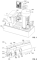
- FIG.1 An example of a machine tool for hard finishing of gears by generating grinding is shown.
- the machine has a machine bed 100 on which a tool carrier 200 is arranged so as to be displaceable along a horizontal feed direction X.
- a Z-slide 210 is arranged on the tool carrier 200 so as to be displaceable along a vertical direction Z.
- the Z-slide 210 carries a swivel body 220 which can be swiveled relative to the Z-slide 210 about a horizontal swivel axis A.
- the swivel axis A runs parallel to the feed direction X.
- a tool head 300 which is only shown symbolically and is described in more detail below, is arranged on the swivel body 220.
- a pivotable workpiece carrier in the form of a rotating turret 400 is also arranged on the machine bed 100.
- the rotating turret 400 can be pivoted about a vertical pivot axis C3 between several rotational positions. It carries two workpiece spindles 500, on each of which a workpiece 510 can be clamped. Each of the workpiece spindles 500 can be driven to rotate about a workpiece axis.
- the workpiece axis of the visible workpiece spindle 500 is designated C2.
- the workpiece axis of the Fig.1 The workpiece spindle that is not visible is referred to as the C1 axis.
- the two workpiece spindles are located on the turret 400 in diametrically opposite positions (ie offset by 180° with respect to the swivel axis C3). In this way, one of the two workpiece spindles can be loaded and unloaded while a workpiece is being machined on the other workpiece spindle. This largely avoids undesirable idle times.
- a machine concept of this kind is, for example, WO 00/035621 A1 known.
- the machine has a machine control 700, which is only shown symbolically and which comprises several control modules 710 and an operating panel 720. Each of the control modules 710 controls a machine axis and/or receives signals from sensors.
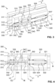
- the tool head comprises a base 310 which is rigidly connected to the swivel body 220.
- a linear guide 311 is formed on the base 310.
- a first spindle unit 320 and a second spindle unit 330 are guided on the linear guide 311 so as to be displaceable along a shift direction Y.
- the spindle units each have corresponding guide shoes 326, 336.
- the shift direction Y runs perpendicular to the X-axis and at an angle to the Z-axis that can be adjusted around the A-axis. Between the A tool 340 is held in spindle units 320, 330.
- the second spindle unit 320 and the first spindle unit 330 can be coupled to one another after the tool 340 has been received between them. In the coupled state, they can be moved together along the shift direction Y with a shift drive (not shown in the drawing) and a ball screw drive 312 in order to change the tool area that engages a workpiece 510 on the C1 axis along the tool axis.
- a shift drive not shown in the drawing
- a ball screw drive 312 in order to change the tool area that engages a workpiece 510 on the C1 axis along the tool axis.
- the spindle unit 320 is a motor spindle with a drive motor 324, which directly drives a first spindle shaft 322 for rotation about a tool spindle axis B.
- the tool spindle axis B runs parallel to the shift direction Y.
- the first spindle shaft 322 is mounted in the spindle housing 321 of the first spindle unit 320 at three bearing points in spindle bearings 323, 323', 323".
- the bearing points are located at different axial positions along the first spindle shaft 322. Two of these bearing points are located between the drive motor 324 and the tool-side end of the first spindle unit 320.
- the corresponding spindle bearings 323, 323' form a fixed-loose bearing or a support bearing, i.e. at least one of these bearing points the spindle bearings can absorb both radial and axial forces.
- Another bearing point is located on the side of the drive motor 324 facing away from the tool.
- the spindle bearing 323" arranged at this bearing point is designed as a loose bearing, i.e. it absorbs radial forces but enables axial movements.
- Each of the three bearing points defines a radial bearing plane.
- the bearing planes are orthogonal to the tool spindle axis B.
- the bearing plane for the bearing point that is closest to the tool-side end of the first spindle shaft 322 is shown as the first bearing plane L1.
- the corresponding spindle bearing closest to the tool is the spindle bearing 323.
- the second spindle unit 330 is a non- driven counter spindle.
- the second spindle unit 330 has a second spindle shaft 332, which is mounted in the spindle housing 331 of the second spindle unit 330 at two bearing points along the spindle shaft in spindle bearings 333, 333'.
- these spindle bearings can be designed as fixed bearings or floating bearings.
- Each of the two bearing points in turn defines a radial bearing plane.
- the bearing plane for the bearing point that is closest to the tool-side end of the second spindle shaft 332 is shown as the second bearing plane L2.
- the corresponding spindle bearing closest to the tool is the spindle bearing 333.
- the tool 340 has a tool holder 341 that carries a helically profiled, dressable grinding wheel 342.
- the tool holder 341 is designed as a mounting flange for the grinding wheel in accordance with DIN ISO 666:2013-12.
- the tool holder 341 has a taper holder with a flat surface at each end, for example a short taper holder 1:4 in accordance with DIN ISO 702-1:2010-04.
- Opposing spindle noses 325, 335 are formed on the tool-side ends of the spindle shafts 322, 332.
- the shape of the spindle noses 325, 335 is complementary to the shape of the taper holders of the tool holder 341. They each have a shape that tapers towards the tool 340 and a flat contact surface on their respective front side.
- each spindle nose can be designed as a taper shank 1:4 in accordance with DIN ISO 702-1:2010-04.
- the conical connections can have different diameters at the two ends of the tool to ensure that the tool 340 can only be accommodated in the correct orientation between the spindle shafts 322, 332.
- the tool 340 is axially clamped between the spindle shafts 332, 332 by means of a pull rod 370 and a clamping nut 372.
- the tool 340 and the second spindle shaft 332 each have a continuous central axial bore.
- the first spindle shaft 322 also has a central axial bore at its tool-side end. In the present example, this hole is not continuous. It is open on the tool side, and an internal thread is formed in the hole.
- the pull rod 370 is pushed through the central holes of the spindle shaft 332 and the tool 340.
- the pull rod 370 has an external thread on its end pointing towards the first spindle unit 320, which is screwed into the internal thread of the first spindle shaft 322.
- the clamping nut 372 is screwed onto this external thread. By tightening the clamping nut 372, the clamping nut 372 exerts axial pressure on the second spindle shaft 332 in the direction of the tool 340. This axially clamps the tool 340 between the spindle shafts 332, 332. Overall, this creates a single, continuous shaft with high rigidity.
- a first balancing unit 350 is arranged on the first spindle shaft 322 in the axial region between the housing 321 of the first spindle unit 320 and the tool 340.
- a second balancing unit 360 is arranged on the second spindle shaft 332 axially between the housing 331 of the second spindle unit 330 and the tool 340.
- the balancing units 350, 360 surround the respective spindle shaft 322, 332 outside the housing of the respective spindle unit 320, 330. They each have a housing that tapers from the associated spindle unit in the direction of the tool 340.
- the tapered outer contour of the balancing units 350, 360 reduces the risk of collisions between the balancing devices and a workpiece 510.
- Each of the balancing units 350, 360 is designed as a ring balancing system.
- each of the balancing units 350, 360 has a rotor with two balancing rings that surround the respective spindle shaft and are carried by it.
- Each of the balancing units 350, 360 also has a stator. This is connected to the respective spindle housing 321, 331.
- the stator contains sensors for detecting vibrations of the respective spindle housing, the speed of the respective spindle shaft and the angular position of each balancing ring.
- the stator also contains an actuator with a coil arrangement in order to change the angular position of the balancing rings on the respective spindle shaft without contact.
- the first balancing unit 350 defines a first balancing plane E1 in which the balancing rings of this balancing unit are arranged.
- the first balancing plane E1 runs orthogonally to the Tool spindle axis B. It runs parallel to the first bearing plane L1 and to a radial center of gravity plane of the tool 340. With respect to the tool spindle axis B, the first balancing plane E1 is located between the center of gravity plane M and the first bearing plane L1, outside the first spindle housing 321.
- the second balancing unit 360 defines a second balancing plane E2 in which the balancing rings of this balancing unit are arranged.
- This balancing plane is located between the center of gravity plane M and the second bearing plane L2, outside the second spindle housing 331.
- a system for automatic balancing in two planes E1, E2 is illustrated in a highly schematic manner.
- Vibration sensors 351, 361 and actuators 352, 362 of the two balancing units 350, 360 interact with a control device 730.
- the control device 730 can be integrated into the machine control 700 or designed separately.
- the angular positions of the balancing rings of both balancing units 350, 360 are automatically calculated and adjusted so that the resulting correction imbalances 353, 363 compensate for the static and dynamic imbalance of the system consisting of the tool 340 and the spindle shafts 322, 332 clamped thereto and vibrations of the spindle housings 321, 331 are minimized accordingly.
- the system is balanced in the two balancing planes E1, E2.
- Ring balancing systems with a control device for automatic two-plane balancing are known and are commercially available from various suppliers.
- One example is the electromagnetic ring balancing system AB 9000 from Hofmann Mess- und Auswuchttechnik GmbH & Co. KG, Pfungstadt, Germany.
- a tool head 300' according to a second embodiment is illustrated.
- the same or equivalent components as in the first and second embodiment are given the same reference numerals as in the Figures 2 to 5 provided.
- the tool head 300' of the second embodiment differs from the Tool head 300 of the first embodiment in that the two spindle units 320, 330 are accommodated in a common spindle housing 380. This is guided with guide shoes 386 on the linear guide 311 along the shift direction Y.
- the second spindle unit 330 is retracted axially relative to the spindle housing 380.
- the spindle bearings 333 of the second spindle unit are accommodated in a bearing holder 391.
- the bearing holder 391 is a bearing bush, which can be designed as a sliding bush or ball roller bush, for example.
- the bearing holder 391 is guided in the spindle housing 380 so that it can be moved axially.
- the rotor 361 of the second balancing unit 360 is axially displaceable relative to the stator 362 of this balancing unit.
- the outer diameter of the rotor 361 is smaller than the inner diameter of the area of the spindle housing 380 in which the bearing holder 391 is guided.
- the second balancing unit 360 in such a way that the entire second balancing unit 360, i.e. both the rotor 361 and the stator 362, can be retracted together with the second spindle unit 330 in order to change the tool.
- a tool head 300" is illustrated according to a third embodiment.
- the same or equivalent components as in the first and second embodiments are given the same reference numerals as in the Figures 2 to 6 provided.
- the tool head 300" of the third embodiment differs from the tool head 300 of the first embodiment in that the second spindle unit 330 is also designed as a motor spindle, with a second drive motor 334.
- the second drive motor 334 is smaller in size than the first drive motor 324, so that it less than half of the total torque is generated on the tool 340, e.g. between 35% and 45% of the total torque. This asymmetrical distribution of the torque generation between the two drive motors 324, 334 avoids disturbing resonances.
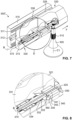
- the clamping nut 372 has a base element 373 which defines a central bore with an internal thread in order to screw the base element 373 onto a pull rod with a corresponding external thread.
- the base element 373 is designed on the outside in the manner of a hexagon nut.
- a support ring 374 is attached to the base element 373. This rests against a collar of the base element 373 in such a way that it is prevented from axial movement in one direction (in the Fig.9 to the left).
- an annular axial pressure element 375 is guided axially displaceably on the base element 373.
- actuating elements 376 in the form of pressure screws are screwed into the axial pressure element 375 and are axially supported on the support ring 374 in such a way that they can be moved along one direction (in the Fig.9 to the left) are prevented from axial movement.
- the axial pressure element 375 is moved relative to the base element 373 along the direction opposite to the support direction (in Fig.9 to the right).
- the axial pressure element 375 is first moved completely back relative to the base element 373 by screwing the pressure screws as far as possible into the axial pressure element 375.
- the clamping nut 372 is then screwed onto the pull rod 370 and positioned against the second spindle shaft 332 using the hexagon on the outside of the base element 373. This is done with a relatively low torque.
- the ring-shaped axial pressure element 375 is then pushed forward in a controlled manner in the direction of the second spindle shaft 332 using the pressure screws until the desired clamping force acts on the tool 340.
- the axial pressure element 375 rests against the second spindle shaft 332 with an annular contact surface.
- clamping nuts can also be used, as are known from the state of the art.
- the force can be transmitted in a different way than shown, for example.
- a hydraulic clamping nut can be used.
- a clamping element can also be used that can be connected to the pull rod in a way other than a screw connection, e.g. via a bayonet or a clamping bush.
- the interface between the spindle shafts 322, 332 and the tool 340 can also be designed differently than in the embodiments described above.
- a different type of conical connection can be used. Any known conical connection can be used, e.g. the versions A, BF, BM, CF or CM specified in DIN ISO 666:2013-12.
- Any known conical connection can be used, e.g. the versions A, BF, BM, CF or CM specified in DIN ISO 666:2013-12.
- DIN ISO 666:2013-12 e.g. the versions A, BF, BM, CF or CM specified in DIN ISO 666:2013-12.
- DIN ISO 666:2013-12 e.g. the versions A, BF, BM, CF or CM specified in DIN ISO 666:2013-12.
- DIN ISO 666:2013-12 e.g. the versions A, BF, BM, CF or CM specified in DIN ISO 666:2013-12.
- DIN ISO 666:2013-12 e.
- the pull rod 370 can extend through the first spindle shaft 322 instead of through the second spindle shaft 332 and be connected at its end to the second spindle shaft 332.
- the clamping element then exerts an axial force on the first spindle shaft in the direction of the second spindle shaft.
- two or more pull rods can be used instead of a central pull rod or in addition thereto, which run parallel to one another and radially spaced from the tool spindle axis B and are arranged in different angular positions relative to the tool spindle axis B.
- the tool can also be fixed between the first spindle shaft and the second spindle shaft in a way other than with a continuous drawbar, for example with clamping elements arranged inside the respective spindle shaft. clamping systems.
- the connection between the tool and the spindle shafts can be made, for example, via hollow shank tapers in accordance with ISO 12164-1:2001-12 and ISO 12164-2:2001-12.
- the tool can be designed differently than in the embodiments explained above.
- the tool can be designed in one piece.
- the tool can be a non-dressable CBN grinding worm whose CBN coating is applied directly to a tool base body.
- the interfaces to the spindle noses 325, 335 are then formed directly on the tool base body instead of on a separate tool carrier.
- the tool does not necessarily have to be a grinding worm. It can also be, for example, a profile grinding wheel, a combination of two or more profile grinding wheels or a combination of one or more grinding worms and one or more profile grinding wheels.
- the spindle bearings 323 are rolling bearings. Instead, other types of spindle bearings can also be used, e.g. hydrostatic, hydrodynamic or aerodynamic bearings, as is known in the art.
- direct drives are used as drive motors. Instead, it is also conceivable to use gear motors.
- ring balancing systems are preferably used as balancing devices
- other types of balancing devices are also conceivable, e.g. hydro-balancing systems, as are known from the state of the art.
- balancing is carried out by injecting a liquid into balancing chambers that are distributed in the circumferential direction.
Landscapes
- Engineering & Computer Science (AREA)
- Mechanical Engineering (AREA)
- Physics & Mathematics (AREA)
- General Physics & Mathematics (AREA)
- Turning (AREA)
- Gear Processing (AREA)
- Constituent Portions Of Griding Lathes, Driving, Sensing And Control (AREA)
- Machine Tool Units (AREA)
Claims (15)
- Tête d'outil (300) pour une machine-outil, en particulier pour une machine à tailler les engrenages, présentant :une première unité de broche (320) avec un premier arbre de broche (322), qui est logé dans la première unité de broche (320) de manière à pouvoir tourner autour d'un axe de broche d'outil (B) ;un premier dispositif d'équilibrage (350) associé à la première unité de broche (320) ;une deuxième unité de broche (330) comprenant un deuxième arbre de broche (332) qui est logé dans la deuxième unité de broche (330) de manière à pouvoir tourner autour de l'axe de broche d'outil (B) ; etun deuxième dispositif d'équilibrage (360) associé à la deuxième unité de broche (330),la première unité de broche (320) et la deuxième unité de broche (330) étant disposées coaxialement l'une par rapport à l'autre de telle sorte qu'un outil (340) puisse être reçu axialement entre le premier arbre de broche (322) et le deuxième arbre de broche (332),caractériséen ce que le premier dispositif d'équilibrage (350) entoure radialement le premier arbre de broche (322) et est disposé axialement entre un palier de broche (323) côté outil de la première unité de broche (320) et une extrémité côté outil du premier arbre de broche (322), et/ouen ce que le deuxième dispositif d'équilibrage (360) entoure radialement le deuxième arbre de broche (332) et est disposé axialement entre un palier de broche (333) côté outil de la deuxième unité de broche (330) et une extrémité côté outil du deuxième arbre de broche (332).
- Tête d'outil (300) selon la revendication 1, dans laquelle l'outil (340) peut être serré entre le premier arbre de broche (322) et le deuxième arbre de broche (332) de telle sorte qu'une force de pression axiale agisse sur l'outil (340) entre le premier arbre de broche (322) et le deuxième arbre de broche (332).
- Tête d'outil (300) selon la revendication 2,dans lequel le deuxième arbre de broche (332) comporte au moins un alésage axial, dans lequel la tête d'outil (300) comprend au moins une barre de traction (370) s'étendant à travers l'alésage axial du deuxième arbre de broche (332), la barre de traction (370) pouvant être reliée à une première extrémité au premier arbre de broche (322), etla barre de traction (370) pouvant être reliée à une deuxième extrémité au deuxième arbre de broche (332) de telle sorte qu'une force de pression axiale puisse être générée sur l'outil (340) entre le premier arbre de broche (322) et le deuxième arbre de broche (332).
- Tête d'outil selon la revendication 3,la tête d'outil (300) comprenant un élément de serrage (372) qui peut être connecté à la barre de traction (370) au niveau de sa deuxièmee extrémité et qui est conçu pour pousser le deuxième arbre de broche (332) axialement vers le premier arbre de broche (322),l'élément de serrage comprenant de préférence :un élément de base (373) qui peut être relié de manière rigide à la barre de traction (370) ;un élément de pression axiale (375) mobile axialement par rapport à l'élément de base (373) en direction du deuxième arbre de broche (332) pour pousser le deuxième arbre de broche (332) axialement vers le premier arbre de broche (322) ; etau moins un élément d'actionnement (376), l'élément d'actionnement (376) étant mobile par rapport à l'élément de base (373) pour déplacer axialement l'élément de pression axiale (375) par rapport à l'élément de base (373).
- Tête d'outil (300) selon l'une quelconque des revendications précédentes,un premier nez de broche (325) étant réalisé à l'extrémité côté outil du premier arbre de broche (322) de telle sorte qu'une liaison par adhérence et/ou par obstacle avec l'outil (340) puisse être réalisée sur le premier nez de broche (325) par une force de pression axiale, en particulier une liaison conique, de préférence une liaison conique avec appui plan, etun deuxième nez de broche (335) étant réalisé à l'extrémité côté outil du deuxième arbre de broche (332) de telle sorte qu'une liaison par adhérence et/ou par obstacle avec l'outil (340) puisse être réalisée sur le deuxième nez de broche (335) par une force de pression axiale, en particulier une liaison conique, de préférence une liaison conique avec appui plan.
- Tête d'outil (300) selon la revendication 5,
le premier nez de broche (325) et le deuxième nez de broche (335) étant formés différemment de telle sorte que l'outil (340) ne puisse être reçu entre les nez de broche (325, 335) que dans une position prédéterminée. - Tête d'outil (300) selon l'une quelconque des revendications précédentes,le premier palier de broche (323) côté outil définissant un premier plan de palier (L1) perpendiculaire à l'axe de broche d'outil (B),le deuxième palier de broche (333) côté outil définissant un deuxième plan de palier (L2) perpendiculaire à l'axe de broche d'outil (B),le premier dispositif d'équilibrage (350) définissant un premier plan d'équilibrage (E1) perpendiculaire à l'axe de broche d'outil (B),le deuxième dispositif d'équilibrage (360) définissant un deuxième plan d'équilibrage (E2) perpendiculaire à l'axe de broche d'outil (B), etle premier plan d'équilibrage (E1) étant disposé entre le premier plan de palier (L1) et le deuxième plan d'équilibrage (E2) et/ou le deuxième plan d'équilibrage (E2) étant disposé entre le deuxième plan de palier (L2) et le premier plan d'équilibrage (E1).
- Tête d'outil (300) selon l'une quelconque des revendications précédentes, dans laquelle le premier et/ou le deuxième dispositif d'équilibrage (350, 360) est conçu comme un système d'équilibrage annulaire.
- Tête d'outil (300) selon l'une quelconque des revendications précédentes, dans laquelle le premier et/ou le deuxième dispositif d'équilibrage (350, 360) comporte au moins un actionneur (352, 362) pour déplacer un balourd de correction (353, 363) du dispositif d'équilibrage concerné (350, 360) par commande numérique.
- Tête d'outil (300) selon l'une quelconque des revendications précédentes,présentant au moins un capteur de vibrations (351, 361) pour détecter des vibrations qui sont provoquées par un balourd dans la tête d'outil (300),un dispositif de commande (730) étant associé à la tête d'outil (300), lequel étant conçu pour détecter des signaux provenant du au moins un capteur de vibrations (351, 361) et pour commander des actionneurs (352, 362) dans le premier et le deuxième dispositif d'équilibrage (350, 360) afin de régler le premier et le deuxième dispositif d'équilibrage (350, 360) en fonction des signaux détectés, de telle sorte que le balourd soit réduit,le dispositif de commande (730) étant de préférence conçu pour effectuer un équilibrage automatique à deux plans.
- Tête d'outil (300) selon l'une quelconque des revendications précédentes,la première unité de broche (320) comprenant un premier boîtier (321) et la deuxième unité de broche (330) comprenant un deuxième boîtier (331), le premier et/ou le deuxième dispositif d'équilibrage (350, 360) étant disposé à l'extérieur du premier et du deuxième boîtier (321, 331), oules première et deuxième unités de broche (320, 330) présentent un boîtier de broche commun (380), et le premier et/ou le deuxième dispositif d'équilibrage (350, 360) étant disposé à l'extérieur du boîtier de broche commun (380).
- Tête d'outil (300) selon la revendication 11, dans laquelle le premier et/ou le deuxième dispositif d'équilibrage (350, 360) présente un contour extérieur qui se rétrécit en direction de l'outil (340).
- Tête d'outil (300) selon l'une quelconque des revendications précédentes,la première unité de broche (320) comprenant un premier moteur d'entraînement (324) conçu pour entraîner le premier arbre de broche (322) de manière à ce que celui-ci effectue une rotation autour de l'axe de broche d'outil (B), et/oula deuxième unité de broche (330) comprenant un deuxième moteur d'entraînement (334) conçu pour entraîner le deuxième arbre de broche (332) de manière à ce que celui-ci effectue une rotation autour de l'axe de broche d'outil (B).
- Tête d'outil (300) selon l'une quelconque des revendications précédentes, présentant en outre un outil (340), en particulier un outil de rectification, de préférence un outil de rectification pour la rectification d'engrenages, qui est serré axialement entre le premier arbre de broche (322) et le deuxième arbre de broche (332) de telle sorte qu'une force de pression axiale agisse sur l'outil (340) entre le premier arbre de broche (322) et le deuxième arbre de broche (332).
- Machine-outil, comprenantune tête d'outil (300) selon l'une quelconque des revendications précédentes ; etau moins une broche porte-pièce (500) pour entraîner une pièce (510) de manière à ce que celle-ci effectue une rotation autour d'un axe de pièce (C1),la machine-outil étant de préférence une machine à tailler les engrenages, en particulier une machine à rectifier les engrenages.
Applications Claiming Priority (2)
| Application Number | Priority Date | Filing Date | Title |
|---|---|---|---|
| CH01623/20A CH718190A1 (de) | 2020-12-18 | 2020-12-18 | Werkzeugkopf für eine Werkzeugmaschine, mit Wuchteinrichtungen. |
| PCT/EP2021/084605 WO2022128635A1 (fr) | 2020-12-18 | 2021-12-07 | Tête d'outil comprenant des dispositifs d'équilibrage et un élément de serrage, et machine-outil comprenant une telle tête d'outil |
Publications (3)
| Publication Number | Publication Date |
|---|---|
| EP4263100A1 EP4263100A1 (fr) | 2023-10-25 |
| EP4263100B1 true EP4263100B1 (fr) | 2024-09-18 |
| EP4263100C0 EP4263100C0 (fr) | 2024-09-18 |
Family
ID=74141217
Family Applications (1)
| Application Number | Title | Priority Date | Filing Date |
|---|---|---|---|
| EP21839338.7A Revoked EP4263100B1 (fr) | 2020-12-18 | 2021-12-07 | Tête d'outil comprenant des dispositifs d'équilibrage et un élément de serrage, et machine-outil comprenant une telle tête d'outil |
Country Status (9)
| Country | Link |
|---|---|
| US (1) | US20240051047A1 (fr) |
| EP (1) | EP4263100B1 (fr) |
| JP (1) | JP2024501807A (fr) |
| KR (1) | KR20230117381A (fr) |
| CN (1) | CN116669887A (fr) |
| CH (1) | CH718190A1 (fr) |
| ES (1) | ES2992992T3 (fr) |
| MX (1) | MX2023007324A (fr) |
| WO (1) | WO2022128635A1 (fr) |
Families Citing this family (4)
| Publication number | Priority date | Publication date | Assignee | Title |
|---|---|---|---|---|
| CH718193A1 (de) * | 2020-12-18 | 2022-06-30 | Reishauer Ag | Werkzeugkopf und Verfahren zum Betrieb eines Werkzeugkopfes. |
| JP7456051B1 (ja) * | 2023-07-18 | 2024-03-26 | Dmg森精機株式会社 | 工作機械 |
| CN117102949B (zh) * | 2023-10-11 | 2025-10-31 | 温岭市大众精密机械有限公司 | 一种高精密cnc数控机床 |
| JP7855777B1 (ja) | 2024-10-29 | 2026-05-08 | ニデックマシンツール株式会社 | 工具ヘッド、工作機械、工具アーバ、および工具ユニット |
Citations (4)
| Publication number | Priority date | Publication date | Assignee | Title |
|---|---|---|---|---|
| JPS60146622A (ja) | 1984-01-07 | 1985-08-02 | Mitsubishi Heavy Ind Ltd | ホブヘツド |
| US4759113A (en) | 1987-06-10 | 1988-07-26 | The Gleason Works | Hob clamping system |
| EP0516596A1 (fr) | 1991-05-31 | 1992-12-02 | MIKRON S.p.A. BOLOGNA | Machine à tailler des roues dentées à la fraise-mère ayant un système de support pour la fraise-mère sans arbre |
| DE102008016497A1 (de) | 2008-03-31 | 2009-10-01 | Liebherr-Verzahntechnik Gmbh | Bearbeitungskopf |
Family Cites Families (11)
| Publication number | Priority date | Publication date | Assignee | Title |
|---|---|---|---|---|
| DE1179787B (de) * | 1961-09-01 | 1964-10-15 | Pfauter Fa Hermann | Vorrichtung an Waelzfraesmaschinen zum Vermindern der Teilungsfehler beim Waelzfraesen von Zahnraedern u. dgl. |
| FR1448597A (fr) * | 1965-09-30 | 1966-08-05 | Staehely Rudolf Maschf | Fraise à développante pour machines à tailler les engrenages |
| GB1349563A (en) * | 1971-03-01 | 1974-04-03 | Werkzeugmasch Okt Veb | Control systems for gear cutting machines |
| DE4337001C2 (de) | 1993-10-29 | 1996-06-27 | Helmut Dipl Ing Ebert | Vorrichtung zum Auswuchten eines fest auf einer rotierenden Welle angeordneten Rotors, insbesondere einer Schleifscheibe |
| US5757662A (en) | 1994-11-29 | 1998-05-26 | Balance Dynamics, Inc. | Eletromagnetically actuated rotating machine unbalance compensator |
| DE19857592A1 (de) | 1998-12-14 | 2000-06-15 | Reishauer Ag | Maschine zum Bearbeiten von vorverzahnten Werkstücken |
| US6257963B1 (en) * | 2000-05-12 | 2001-07-10 | Reishauer Ag | Grinding worm for the continuous generating grinding of gear wheels |
| EP2712694B1 (fr) * | 2012-09-28 | 2017-03-15 | WFL Millturn Technologies GmbH & Co. KG | Support d'outil pour une fraise-mère développante dans un type d'alésage |
| DE102015012818A1 (de) * | 2015-10-05 | 2017-04-06 | Liebherr-Verzahntechnik Gmbh | Bearbeitungskopf mit Wuchteinrichtung |
| DE102017001652A1 (de) * | 2017-02-21 | 2018-08-23 | Liebherr-Verzahntechnik Gmbh | Vorrichtung und Verfahren zur Werkstückbearbeitung auf einer Verzahnmaschine |
| DE102017003648A1 (de) * | 2017-04-13 | 2018-10-18 | Liebherr-Verzahntechnik Gmbh | Verfahren zur Verzahnbearbeitung eines Werkstücks |
-
2020
- 2020-12-18 CH CH01623/20A patent/CH718190A1/de unknown
-
2021
- 2021-12-07 CN CN202180084955.8A patent/CN116669887A/zh active Pending
- 2021-12-07 ES ES21839338T patent/ES2992992T3/es active Active
- 2021-12-07 EP EP21839338.7A patent/EP4263100B1/fr not_active Revoked
- 2021-12-07 MX MX2023007324A patent/MX2023007324A/es unknown
- 2021-12-07 KR KR1020237021924A patent/KR20230117381A/ko not_active Ceased
- 2021-12-07 WO PCT/EP2021/084605 patent/WO2022128635A1/fr not_active Ceased
- 2021-12-07 JP JP2023537022A patent/JP2024501807A/ja active Pending
- 2021-12-07 US US18/268,195 patent/US20240051047A1/en active Pending
Patent Citations (4)
| Publication number | Priority date | Publication date | Assignee | Title |
|---|---|---|---|---|
| JPS60146622A (ja) | 1984-01-07 | 1985-08-02 | Mitsubishi Heavy Ind Ltd | ホブヘツド |
| US4759113A (en) | 1987-06-10 | 1988-07-26 | The Gleason Works | Hob clamping system |
| EP0516596A1 (fr) | 1991-05-31 | 1992-12-02 | MIKRON S.p.A. BOLOGNA | Machine à tailler des roues dentées à la fraise-mère ayant un système de support pour la fraise-mère sans arbre |
| DE102008016497A1 (de) | 2008-03-31 | 2009-10-01 | Liebherr-Verzahntechnik Gmbh | Bearbeitungskopf |
Non-Patent Citations (8)
| Title |
|---|
| "Schaeffler Technisches Taschenbuch", 1 November 2016, SCHAEFFLER TECHNOLOGIES AG & CO. KG, Herzogenaurach, DE, article HARALD MEERKAMM: "Passages; Konstruktionselemente", pages: 414 - 419,426-429, XP009561686 |
| ANONYMOUS: "Die CNC-Wälz-und Profilschleifmaschinen LCS 100 und 150", PROSPEKT LCS 100 UND 150, LIEBHERR-VERZAHNTECHNIK GMBH, 1 July 2011 (2011-07-01), pages 1 - 8, XP093289438, Retrieved from the Internet <URL:http://www.liebherr.com> |
| ANONYMOUS: "Elektromagnetisches Ringauswuchtsystem AB 9000", BROCHURE AKTIVES AUSWUCHTEN, HOFMANN GLOBAL, 1 June 2019 (2019-06-01), pages 1 - 4, XP093289422, Retrieved from the Internet <URL:https://www.hofmann-global.com/fileadmin/user_upload/Downloads/Produktdatenblatt_Auswuchtsysteme/AB9000_de_0717_371-7001.pdf> |
| ANONYMOUS: "Q&A with Alois Mundt", GEAR SOLUTIONS MAGAZINE, 1 August 2009 (2009-08-01), pages 1 - 3, XP093289449, Retrieved from the Internet <URL:https://gearsolutions.com/departments/qa/qa-with-alois-mundt/> |
| D3b - Eidesstattliche Versicherung Dr. Türich |
| D3c - Declaration Krishnamurthy |
| MEHR ANDREAS: "A compact gear grinder for high-performance processes", SIGMA POOL GEAR SEMINAR INDIA; JULY 20 AND 21, 2009 IN CHENNAI; JULY 23 AND 24, 2009 IN PUNE, SIGMA POOL, 20 July 2009 (2009-07-20) - 24 July 2009 (2009-07-24), pages 97 - 113, XP093289447 |
| THOMAS BAUSCH: "Innovative Zahnradfertigung : Verfahren, Maschinen und Werkzeuge zur kostengünstigen Herstellung von Stirnrädern mit hoher Qualität", 1 January 2006, EXPERT-VERL., ISBN: 3-8169-1871-9, article THOMAS BAUSCH: "F.14 Wälzschleifen mit einer Schnecke", pages: 496 - 532, XP009561685 |
Also Published As
| Publication number | Publication date |
|---|---|
| CH718190A1 (de) | 2022-06-30 |
| CN116669887A (zh) | 2023-08-29 |
| JP2024501807A (ja) | 2024-01-16 |
| EP4263100A1 (fr) | 2023-10-25 |
| MX2023007324A (es) | 2023-06-29 |
| WO2022128635A1 (fr) | 2022-06-23 |
| EP4263100C0 (fr) | 2024-09-18 |
| ES2992992T3 (en) | 2024-12-20 |
| KR20230117381A (ko) | 2023-08-08 |
| US20240051047A1 (en) | 2024-02-15 |
Similar Documents
| Publication | Publication Date | Title |
|---|---|---|
| EP4263101B1 (fr) | Tête d'outil et procédé de fonctionnement d'une tête d'outil, et machine-outil comprenant une telle tête d'outil | |
| EP3310530B1 (fr) | Procédé et meuleuse pour le meulage de contours externes et internes de pièces dans un dispositif de serrage | |
| WO2022128635A1 (fr) | Tête d'outil comprenant des dispositifs d'équilibrage et un élément de serrage, et machine-outil comprenant une telle tête d'outil | |
| EP2167277B1 (fr) | Centre de rectification et procédé de rectification simultanée de plusieurs paliers et de surfaces d'extrémité de vilebrequins | |
| DE102012202548B4 (de) | Honmaschine zum Innen- und Außenhonen | |
| DE102007009843B4 (de) | Verfahren zur Schleifbearbeitung eines Maschinenbauteils und Schleifmaschine zur Durchführung des Verfahrens | |
| EP2496382B1 (fr) | Procédé de rectification des paliers principaux et de moyeu d'un vilebrequin par rectification cylindrique extérieure et rectifieuse pour mettre en oeuvre ce procédé | |
| DE19711317C2 (de) | Werkzeugmaschine | |
| EP3153277B1 (fr) | Tete d'usinage dotee d'un dispositif d'equilibrage | |
| DE102008007175B4 (de) | Verfahren zum Schleifen der Haupt- und Hublager einer Kurbelwelle durch Außenrundschleifen und Vorrichtung zur Durchführung des Verfahrens | |
| WO2015021565A1 (fr) | Machine permettant d'usiner des pièces | |
| EP3061554A1 (fr) | Tete d'usinage pour une machine a tailler les engrenages et procede de taille d'engrenage sur une piece usinee, en particulier d'un arbre a vis sans vin ou cremaillere | |
| DE102017001652A1 (de) | Vorrichtung und Verfahren zur Werkstückbearbeitung auf einer Verzahnmaschine | |
| EP2021149B1 (fr) | Machine-outil | |
| DE10303239A1 (de) | Drehschneideinrichtung für eine Kurbelwelle und Verfahren hierfür | |
| EP3999273B1 (fr) | Machine-outil et procédé de laminage de pièces rotatives ayant des profilés en forme de rainure | |
| EP4263133B1 (fr) | Flasque récepteur destiné à un corps d'outil | |
| DE102006028728B4 (de) | Honwerkzeug und Verfahren zum Fertig-Honen von Bohrungen | |
| EP3426434B1 (fr) | Broche d'outil | |
| DE2335542A1 (de) | Bearbeitungsverfahren fuer die insbesondere zerspanende formgebung von maschinenteilen und vorrichtung zur durchfuehrung | |
| EP2883635B1 (fr) | Dispositif d'équilibrage et méthode d'équilibrage pour un magasin de stockage de tiges | |
| EP2602055A1 (fr) | Machine-outil | |
| DE102018119477B4 (de) | Spindelanordnung für eine Werkzeugmaschine | |
| DE19534839A1 (de) | Körnerspitzenvorrichtung, insbesondere zur Aufnahme in eine Reitstockpinole einer Drehmaschine | |
| DE102015121280A1 (de) | Verfahren und Vorrichtung zur Bearbeitung von rotierbaren Werkstücken |
Legal Events
| Date | Code | Title | Description |
|---|---|---|---|
| STAA | Information on the status of an ep patent application or granted ep patent |
Free format text: STATUS: UNKNOWN |
|
| STAA | Information on the status of an ep patent application or granted ep patent |
Free format text: STATUS: THE INTERNATIONAL PUBLICATION HAS BEEN MADE |
|
| PUAI | Public reference made under article 153(3) epc to a published international application that has entered the european phase |
Free format text: ORIGINAL CODE: 0009012 |
|
| STAA | Information on the status of an ep patent application or granted ep patent |
Free format text: STATUS: REQUEST FOR EXAMINATION WAS MADE |
|
| 17P | Request for examination filed |
Effective date: 20230615 |
|
| AK | Designated contracting states |
Kind code of ref document: A1 Designated state(s): AL AT BE BG CH CY CZ DE DK EE ES FI FR GB GR HR HU IE IS IT LI LT LU LV MC MK MT NL NO PL PT RO RS SE SI SK SM TR |
|
| DAV | Request for validation of the european patent (deleted) | ||
| DAX | Request for extension of the european patent (deleted) | ||
| GRAP | Despatch of communication of intention to grant a patent |
Free format text: ORIGINAL CODE: EPIDOSNIGR1 |
|
| RIC1 | Information provided on ipc code assigned before grant |
Ipc: G01M 3/22 20060101ALI20240508BHEP Ipc: B23B 23/00 20060101ALI20240508BHEP Ipc: B23B 31/40 20060101ALI20240508BHEP Ipc: G01M 1/36 20060101ALI20240508BHEP Ipc: B23F 23/12 20060101ALI20240508BHEP Ipc: B23F 23/10 20060101AFI20240508BHEP |
|
| STAA | Information on the status of an ep patent application or granted ep patent |
Free format text: STATUS: GRANT OF PATENT IS INTENDED |
|
| INTG | Intention to grant announced |
Effective date: 20240613 |
|
| GRAS | Grant fee paid |
Free format text: ORIGINAL CODE: EPIDOSNIGR3 |
|
| GRAA | (expected) grant |
Free format text: ORIGINAL CODE: 0009210 |
|
| STAA | Information on the status of an ep patent application or granted ep patent |
Free format text: STATUS: THE PATENT HAS BEEN GRANTED |
|
| AK | Designated contracting states |
Kind code of ref document: B1 Designated state(s): AL AT BE BG CH CY CZ DE DK EE ES FI FR GB GR HR HU IE IS IT LI LT LU LV MC MK MT NL NO PL PT RO RS SE SI SK SM TR |
|
| REG | Reference to a national code |
Ref country code: GB Ref legal event code: FG4D Free format text: NOT ENGLISH |
|
| REG | Reference to a national code |
Ref country code: CH Ref legal event code: EP |
|
| REG | Reference to a national code |
Ref country code: DE Ref legal event code: R096 Ref document number: 502021005212 Country of ref document: DE |
|
| REG | Reference to a national code |
Ref country code: IE Ref legal event code: FG4D Free format text: LANGUAGE OF EP DOCUMENT: GERMAN |
|
| U01 | Request for unitary effect filed |
Effective date: 20240918 |
|
| U07 | Unitary effect registered |
Designated state(s): AT BE BG DE DK EE FI FR IT LT LU LV MT NL PT RO SE SI Effective date: 20241011 |
|
| REG | Reference to a national code |
Ref country code: ES Ref legal event code: FG2A Ref document number: 2992992 Country of ref document: ES Kind code of ref document: T3 Effective date: 20241220 |
|
| PG25 | Lapsed in a contracting state [announced via postgrant information from national office to epo] |
Ref country code: NO Free format text: LAPSE BECAUSE OF FAILURE TO SUBMIT A TRANSLATION OF THE DESCRIPTION OR TO PAY THE FEE WITHIN THE PRESCRIBED TIME-LIMIT Effective date: 20241218 |
|
| U20 | Renewal fee for the european patent with unitary effect paid |
Year of fee payment: 4 Effective date: 20241211 |
|
| PG25 | Lapsed in a contracting state [announced via postgrant information from national office to epo] |
Ref country code: GR Free format text: LAPSE BECAUSE OF FAILURE TO SUBMIT A TRANSLATION OF THE DESCRIPTION OR TO PAY THE FEE WITHIN THE PRESCRIBED TIME-LIMIT Effective date: 20241219 |
|
| PG25 | Lapsed in a contracting state [announced via postgrant information from national office to epo] |
Ref country code: HR Free format text: LAPSE BECAUSE OF FAILURE TO SUBMIT A TRANSLATION OF THE DESCRIPTION OR TO PAY THE FEE WITHIN THE PRESCRIBED TIME-LIMIT Effective date: 20240918 |
|
| PG25 | Lapsed in a contracting state [announced via postgrant information from national office to epo] |
Ref country code: RS Free format text: LAPSE BECAUSE OF FAILURE TO SUBMIT A TRANSLATION OF THE DESCRIPTION OR TO PAY THE FEE WITHIN THE PRESCRIBED TIME-LIMIT Effective date: 20241218 |
|
| PG25 | Lapsed in a contracting state [announced via postgrant information from national office to epo] |
Ref country code: RS Free format text: LAPSE BECAUSE OF FAILURE TO SUBMIT A TRANSLATION OF THE DESCRIPTION OR TO PAY THE FEE WITHIN THE PRESCRIBED TIME-LIMIT Effective date: 20241218 Ref country code: NO Free format text: LAPSE BECAUSE OF FAILURE TO SUBMIT A TRANSLATION OF THE DESCRIPTION OR TO PAY THE FEE WITHIN THE PRESCRIBED TIME-LIMIT Effective date: 20241218 Ref country code: HR Free format text: LAPSE BECAUSE OF FAILURE TO SUBMIT A TRANSLATION OF THE DESCRIPTION OR TO PAY THE FEE WITHIN THE PRESCRIBED TIME-LIMIT Effective date: 20240918 Ref country code: GR Free format text: LAPSE BECAUSE OF FAILURE TO SUBMIT A TRANSLATION OF THE DESCRIPTION OR TO PAY THE FEE WITHIN THE PRESCRIBED TIME-LIMIT Effective date: 20241219 |
|
| PG25 | Lapsed in a contracting state [announced via postgrant information from national office to epo] |
Ref country code: IS Free format text: LAPSE BECAUSE OF FAILURE TO SUBMIT A TRANSLATION OF THE DESCRIPTION OR TO PAY THE FEE WITHIN THE PRESCRIBED TIME-LIMIT Effective date: 20250118 |
|
| PG25 | Lapsed in a contracting state [announced via postgrant information from national office to epo] |
Ref country code: SM Free format text: LAPSE BECAUSE OF FAILURE TO SUBMIT A TRANSLATION OF THE DESCRIPTION OR TO PAY THE FEE WITHIN THE PRESCRIBED TIME-LIMIT Effective date: 20240918 |
|
| PGFP | Annual fee paid to national office [announced via postgrant information from national office to epo] |
Ref country code: ES Payment date: 20250102 Year of fee payment: 4 |
|
| PGFP | Annual fee paid to national office [announced via postgrant information from national office to epo] |
Ref country code: CH Payment date: 20250101 Year of fee payment: 4 |
|
| PG25 | Lapsed in a contracting state [announced via postgrant information from national office to epo] |
Ref country code: CZ Free format text: LAPSE BECAUSE OF FAILURE TO SUBMIT A TRANSLATION OF THE DESCRIPTION OR TO PAY THE FEE WITHIN THE PRESCRIBED TIME-LIMIT Effective date: 20240918 Ref country code: PL Free format text: LAPSE BECAUSE OF FAILURE TO SUBMIT A TRANSLATION OF THE DESCRIPTION OR TO PAY THE FEE WITHIN THE PRESCRIBED TIME-LIMIT Effective date: 20240918 |
|
| PG25 | Lapsed in a contracting state [announced via postgrant information from national office to epo] |
Ref country code: SK Free format text: LAPSE BECAUSE OF FAILURE TO SUBMIT A TRANSLATION OF THE DESCRIPTION OR TO PAY THE FEE WITHIN THE PRESCRIBED TIME-LIMIT Effective date: 20240918 |
|
| PLBI | Opposition filed |
Free format text: ORIGINAL CODE: 0009260 |
|
| PLAX | Notice of opposition and request to file observation + time limit sent |
Free format text: ORIGINAL CODE: EPIDOSNOBS2 |
|
| PG25 | Lapsed in a contracting state [announced via postgrant information from national office to epo] |
Ref country code: MC Free format text: LAPSE BECAUSE OF FAILURE TO SUBMIT A TRANSLATION OF THE DESCRIPTION OR TO PAY THE FEE WITHIN THE PRESCRIBED TIME-LIMIT Effective date: 20240918 |
|
| 26 | Opposition filed |
Opponent name: GLEASON-PFAUTER MASCHINENFABRIK GMBH Effective date: 20250617 |
|
| RDAF | Communication despatched that patent is revoked |
Free format text: ORIGINAL CODE: EPIDOSNREV1 |
|
| PG25 | Lapsed in a contracting state [announced via postgrant information from national office to epo] |
Ref country code: IE Free format text: LAPSE BECAUSE OF NON-PAYMENT OF DUE FEES Effective date: 20241207 |
|
| RDAG | Patent revoked |
Free format text: ORIGINAL CODE: 0009271 |
|
| STAA | Information on the status of an ep patent application or granted ep patent |
Free format text: STATUS: PATENT REVOKED |
|
| REG | Reference to a national code |
Ref country code: CH Ref legal event code: N12 Free format text: ST27 STATUS EVENT CODE: U-0-0-N10-N12 (AS PROVIDED BY THE NATIONAL OFFICE) Effective date: 20251210 |
|
| 27W | Patent revoked |
Effective date: 20250902 |
|
| GBPR | Gb: patent revoked under art. 102 of the ep convention designating the uk as contracting state |
Effective date: 20250902 |