EP4263111B1 - Dispositif de gravure au laser pour de multiples faisceaux laser faisant appel à une liaison de données pour ajuster la position de focalisation - Google Patents
Dispositif de gravure au laser pour de multiples faisceaux laser faisant appel à une liaison de données pour ajuster la position de focalisation Download PDFInfo
- Publication number
- EP4263111B1 EP4263111B1 EP20829029.6A EP20829029A EP4263111B1 EP 4263111 B1 EP4263111 B1 EP 4263111B1 EP 20829029 A EP20829029 A EP 20829029A EP 4263111 B1 EP4263111 B1 EP 4263111B1
- Authority
- EP
- European Patent Office
- Prior art keywords
- laser
- engraving device
- optical sensor
- engraving
- target surface
- Prior art date
- Legal status (The legal status is an assumption and is not a legal conclusion. Google has not performed a legal analysis and makes no representation as to the accuracy of the status listed.)
- Active
Links
Images
Classifications
-
- B—PERFORMING OPERATIONS; TRANSPORTING
- B23—MACHINE TOOLS; METAL-WORKING NOT OTHERWISE PROVIDED FOR
- B23K—SOLDERING OR UNSOLDERING; WELDING; CLADDING OR PLATING BY SOLDERING OR WELDING; CUTTING BY APPLYING HEAT LOCALLY, e.g. FLAME CUTTING; WORKING BY LASER BEAM
- B23K26/00—Working by laser beam, e.g. welding, cutting or boring
- B23K26/36—Removing material
- B23K26/362—Laser etching
-
- B—PERFORMING OPERATIONS; TRANSPORTING
- B23—MACHINE TOOLS; METAL-WORKING NOT OTHERWISE PROVIDED FOR
- B23K—SOLDERING OR UNSOLDERING; WELDING; CLADDING OR PLATING BY SOLDERING OR WELDING; CUTTING BY APPLYING HEAT LOCALLY, e.g. FLAME CUTTING; WORKING BY LASER BEAM
- B23K26/00—Working by laser beam, e.g. welding, cutting or boring
- B23K26/02—Positioning or observing the workpiece, e.g. with respect to the point of impact; Aligning, aiming or focusing the laser beam
- B23K26/03—Observing, e.g. monitoring, the workpiece
- B23K26/032—Observing, e.g. monitoring, the workpiece using optical means
-
- B—PERFORMING OPERATIONS; TRANSPORTING
- B23—MACHINE TOOLS; METAL-WORKING NOT OTHERWISE PROVIDED FOR
- B23K—SOLDERING OR UNSOLDERING; WELDING; CLADDING OR PLATING BY SOLDERING OR WELDING; CUTTING BY APPLYING HEAT LOCALLY, e.g. FLAME CUTTING; WORKING BY LASER BEAM
- B23K26/00—Working by laser beam, e.g. welding, cutting or boring
- B23K26/02—Positioning or observing the workpiece, e.g. with respect to the point of impact; Aligning, aiming or focusing the laser beam
- B23K26/06—Shaping the laser beam, e.g. by masks or multi-focusing
- B23K26/064—Shaping the laser beam, e.g. by masks or multi-focusing by means of optical elements, e.g. lenses, mirrors or prisms
- B23K26/0648—Shaping the laser beam, e.g. by masks or multi-focusing by means of optical elements, e.g. lenses, mirrors or prisms comprising lenses
-
- B—PERFORMING OPERATIONS; TRANSPORTING
- B23—MACHINE TOOLS; METAL-WORKING NOT OTHERWISE PROVIDED FOR
- B23K—SOLDERING OR UNSOLDERING; WELDING; CLADDING OR PLATING BY SOLDERING OR WELDING; CUTTING BY APPLYING HEAT LOCALLY, e.g. FLAME CUTTING; WORKING BY LASER BEAM
- B23K26/00—Working by laser beam, e.g. welding, cutting or boring
- B23K26/02—Positioning or observing the workpiece, e.g. with respect to the point of impact; Aligning, aiming or focusing the laser beam
- B23K26/06—Shaping the laser beam, e.g. by masks or multi-focusing
- B23K26/0665—Shaping the laser beam, e.g. by masks or multi-focusing by beam condensation on the workpiece, e.g. for focusing
-
- B—PERFORMING OPERATIONS; TRANSPORTING
- B23—MACHINE TOOLS; METAL-WORKING NOT OTHERWISE PROVIDED FOR
- B23K—SOLDERING OR UNSOLDERING; WELDING; CLADDING OR PLATING BY SOLDERING OR WELDING; CUTTING BY APPLYING HEAT LOCALLY, e.g. FLAME CUTTING; WORKING BY LASER BEAM
- B23K26/00—Working by laser beam, e.g. welding, cutting or boring
- B23K26/02—Positioning or observing the workpiece, e.g. with respect to the point of impact; Aligning, aiming or focusing the laser beam
- B23K26/06—Shaping the laser beam, e.g. by masks or multi-focusing
- B23K26/067—Dividing the beam into multiple beams, e.g. multi-focusing
- B23K26/0676—Dividing the beam into multiple beams, e.g. multi-focusing into dependently operating sub-beams, e.g. an array of spots with fixed spatial relationship or for performing simultaneously identical operations
Definitions
- the present invention relates to a laser engraving device for multiple laser beams for processing a target surface, and to a method of engraving a target surface by using a laser engraving device, see claims 1 and 15.
- the target surface may be for instance a non-patterned coating of a glazing unit installed on a train or in a building.
- a patterned coating can be obtained which would improve the penetration of electromagnetic waves through the coating in the radio frequency spectrum used for wireless communications.
- energy saving windows In order to reduce energy consumption of for example trains and buildings, energy saving windows with better thermal properties are increasingly used. These energy saving windows are typically composed of two or more windowpanes. The thickness of the glass panes is selected to satisfy mechanical requirements of the glazing unit given by regulations. The gap between the glass panes suppresses acoustic noise, and it also improves thermal insulation. Energy saving windows typically comprise one or more coated glass panes. This coating has a low thermal emissivity and therefore reduces the heat transfer by radiation. It can also be a sun protection coating, reducing the transmission in the near infrared region.
- Electromagnetic (EM) waves used for telecommunications are thus strongly attenuated. This is problematic, as nowadays, wireless communications are increasingly used.
- the FSS is a thin and repetitive surface designed to reflect, transmit or absorb electromagnetic fields.
- the FSS is able to make the coating, and thus the glazing unit substantially transparent to EM waves used in wireless telecommunications.
- the achieved effect is not limited to any specific frequency band, and the FSS makes it possible to achieve low attenuation for a large band of frequencies including the frequencies used in current wireless communication systems, such as global system for mobile communications (GSM), long-term evolution(LTE), multiple-input and multiple-output (MIMO), and future ones.
- GSM global system for mobile communications
- LTE long-term evolution
- MIMO multiple-input and multiple-output
- repeaters It is also known to install repeaters in trains or buildings with poor indoor signal coverage. Repeaters consist of an antenna placed outside and another one placed inside, which is connected to an amplifier to increase the signal inside the train or building. This solution is technology-dependent, and a repeater works for a defined range of frequencies only. Since telecommunication standards evolve quickly, repeaters have to be often renewed (i.e., typically between 5 and 8 years). Furthermore, the repeater-based systems use a chipset and active components, which are prone to frequent failures. Moreover, repeaters have a high energy consumption. This reduces the energy savings achieved by modern windows.
- US2019101443A1 discloses a laser processing apparatus that includes a branching unit configured to branch a laser beam to a first optical path and a second optical path, a condenser configured to condense the branched laser beams on a processing face of a workpiece, an output power measuring unit configured to measure the output power of the laser beam emitted from a laser beam generation unit and having passed through the condenser, and a blocking member positioning mechanism disposed between the condenser and the output power measuring unit and capable of positioning a blocking member between a first laser beam blocking position at which the blocking member blocks only the laser beam of the first optical path from between the branched laser beams and a retracted position at which the blocking member blocks none of the laser beams.
- US2006196858A1 relates to a method and an apparatus for laser marking indicia in the volume of gemstones such as diamonds, the indicia being made up of a plurality of microscopic dot-shaped marks whose build-up can be initiated by exposing naturally-occurring internal defects or impurities in the volume of a gemstone to a tightly focused train of laser pulses.
- Authentication data is encoded in the gemstone from the relative spatial arrangement of the dot-shaped marks that form the indicium.
- US2020209523A1 discloses a laser processing apparatus that includes a laser light output section, a laser light scanning section, a distance measurement light emitting section which emits distance measurement light, a pair of light receiving elements which receives the distance measurement light emitted from the distance measurement light emitting section and reflected by the workpiece.
- one of the aims of the present invention is to provide a device that can be used to engrave an electrically conductive coating to generate a patterned or structured coating. Compared with non-patterned coatings, the patterned coating would reduce the attenuation for EM waves used in telecommunications, and it would have an improved performance.
- a laser engraving device as recited in claim 1.
- the invention allows laser processing of any surface having any shape.
- the device may be used to process an assembled glazing unit, which may have any number of windowpanes, and this with a high focus positioning accuracy.
- This is not achievable with currently known existing laser engraving systems using a mechanical, capacitive, inductive or optical distance sensor.
- fast tracking of the target surface is achieved using an optical sensor, which has a response time of 0.002 ms or even less, and a high-speed focusing element, such as a tunable lens.
- the device may be placed on a motion system, which would allow a high displacement speed (e.g. up to 10 m/s) of the device. It is to be noted that the speed of a standard engraving system using imaging and detection technology is often limited by the response time, which is typically between 20 ms and 100 ms.
- the proposed device comprises a focusing element, there is no need to move the entire device to follow the target surface, which would usually induce a speed limitation due to a mechanical moving part.
- the proposed device has the advantage that the desired pattern can be generated rapidly thanks to the possibility of simultaneously using a plurality of engraving beams to engrave the target surface. More specifically, the use of multiple beams reduces drastically the time of processing. The processing time can thus be reduced by a factor 2 to 20 or even more depending on the number of engraving beams. Standard systems accept only one engraving beam due to the used distance detection or scanning systems.
- the processed glazing unit would have the advantage that it has energy saving capabilities and it is transparent or substantially transparent to broadband EM frequencies including the ones used in telecommunications.
- the processed glazing unit shows a low attenuation for broadband microwave frequencies.
- a laser engraving system comprising the laser engraving device according to the first aspect, and further comprising a motion system.
- the main motivation behind the present invention was to propose a device that can be used to obtain an improved glazing design for windowpanes, especially in situations in which the glazing unit has already been placed in its final installation location.
- the windowpanes should not only satisfy mechanical and tension requirements, but they should also provide low attenuation for broadband frequencies and optionally an advantageous path loss imbalance, particularly between the s (perpendicular) and p (parallel) polarisations, for a wide range of angles of incidence and broadband frequencies used for wireless telecommunication.
- the insulating glazing unit or window is typically assembled from two or more windowpanes. Each windowpane may contain polymer, such as polycarbonate or acrylic glass, and/or glass.
- a structured or patterned coating with low thermal emissivity, i.e., an emissivity value below 20% or approximately 20% (usually named low-e coating), applied to one or more surfaces of the glazing unit generally results in low attenuation for broadband microwave frequencies and optionally also in a small path loss imbalance between parallel and perpendicular polarisations, which may improve MIMO efficiency.
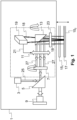
- FIG. 1 schematically illustrates the laser engraving device 1, apparatus or optical auto-focusing system for multiple laser beam processing, also referred to as a laser head, according to the first embodiment of the present invention.
- a laser source 3 or isolator which may or may not be part of the laser head 1, is provided to generate a light or laser beam, also referred to as a processing laser beam or working laser beam 25, that is directed to a first mirror, which in this case is a dichroic mirror 5, also known as a dichroic filter.
- the laser source (where the letters in the word stand for "Light Amplification by Stimulated Emission of Radiation" is configured to produce a very narrow beam of light. In the produced narrow beam of light all of the light waves have very similar wavelengths.
- a dichroic mirror is a thin-film filter or interference filter, which operates as a very accurate colour filter used to selectively pass light of a small range of colours while reflecting other colours.
- the dichroic mirror 5 is configured to reflect the incoming laser beam from the laser source towards a beam splitter 7, beam multiplier or beam divider, while it allows a visible light beam reflected from the target surface to pass through it towards an optional vision system 9, which the user or technician may use to visually inspect the progress or quality of the engraving process.
- the beam splitter 7 is an optical device that is configured to split a beam of light in two or more beams of light.
- the beam splitter is a diffractive beam splitter, also known as a multi-spot beam generator or an array beam generator, which is a single optical element that divides an input beam into N output beams. Each output beam retains the same optical characteristics as the input beam, such as size, polarisation and phase.
- a diffractive beam splitter can generate either a 1-dimensional beam array (1 x N) or a 2-dimensional beam matrix (M x N), depending on the diffractive pattern on the optical element.
- the diffractive beam splitter is used with monochromatic light such as a laser beam, and is designed for a specific wavelength and angle of separation between output beams. In the present example, the number of generated beams is between 2 and 20, or it could more specifically be between 6 and 20. These output beams are in the following text also referred to as engraving beams 27.
- the laser head 1 further comprises a first optical focusing element 11 in the path of the beams coming from the beam splitter 7.
- the first focusing element is used to adjust the focal point of the laser beams that travel through it to minimise defocus aberration.
- the focusing element may comprise a lens, such as a mechanically movable lens, or alternatively, a tunable lens, also called a liquid lens, may be used.
- the laser head 1 also comprises a second mirror 13, which may be a state-of-the art mirror to redirect the incoming engraving laser beams towards the target surface.
- the glazing unit comprises two windowpanes, namely a first windowpane 15 1 and a second windowpane 15 2 .
- the glazing unit could comprise any number of panes.
- These windowpanes are arranged in this example so that the engraving beams first traverse the first windowpane 15 1 before reaching the second windowpane 15 2 .
- the coating 17 to be engraved and which thus also has the target surface, is placed on the inner surface of the second windowpane. In other words, the exposed surface of the coating is facing the gap between the first and second windowpanes.
- the coating to be engraved could be placed on any surface of any one of the windowpanes, and the proposed laser head 1 would be able to engrave it.
- the gap may be filled with gas, such as air or argon, to improve the thermal and/or acoustic noise insulating properties of the glazing unit.
- the windowpanes are typically laminated elements. More specifically, they comprise at least two layers attached, bonded, fixed or glued together, but they may be one-layer panes instead. For example, a polymer layer is often sandwiched and bonded between two glass layers.
- the double ended arrow next to the windowpanes in Figure 1 indicates the focusing range of the first optical focusing element 11.
- the laser head 1 also comprises a distance measurement device or distance sensor 19, which in this example is an optical sensor, or more specifically an optical distance sensor.
- the optical distance sensor is configured to measure the distance between the optical distance sensor and the target surface 17 by emitting a measurement beam or light 18 and by detecting the position of the reflected beam or light on the target surface 17. In this manner, the distance between the optical distance sensor and any of the reflecting surfaces may be detected. More specifically, the distance measurement is based on the triangulation principle.
- the measurement (laser) beam strikes the target surface as a small point.
- the receiver of the sensor photodiode line) detects the position of this point. The angle of incidence changes according to the distance, and thereby the position of the laser point on the receiver.
- the photodiode line is read by an integrated microcontroller.
- the controller accurately calculates the angle from the light distribution on the photodiode line and then calculates the distance to the object from this. This distance is either issued at the serial port or converted into an output current proportional to the distance.
- the microcontroller guarantees a high degree of linearity and measuring precision.
- an optical displacement sensor can be used for this application.
- the principle of laser displacement sensor ranging is a method where triangulation is applied by combining the emitting element and the position sensitive device (PSD) of the laser displacement sensor to perform ranging (detecting the amount of displacement).
- the distance sensor 19 is connected to the first optical focusing element 11 by a data link 21, which is, according to the present invention, a wire data connection, such as an electrical conductor, or a wireless data connection.
- the laser head 1 optionally also comprises a second optical focusing element 23, which in this example is a fisheye lens, and more specifically an f-theta lens, also known as a flat lens or a scanning lens, which is a type of fisheye lens.
- the f-theta lenses are designed to produce a focused spot in a flat field, the position of the spot being proportional to the focal length (f) of the lens and the angle (theta) of the beam entering the lens, giving them the name f-theta lenses.
- the size of the focused spot is constant throughout the field.
- the optional f-theta lens 23 is placed in the path of the engraving beams 27 to focus the different beams in the same plane (instead of them being focused on a sphere).
- the second optical focusing element 23 is the element closest to the coating to be engraved.
- the laser head 1 may be placed on a motion system (not illustrated in the drawings), such as a robotic arm, that may be configured to rotate around any number of rotation axes, such as around three orthogonally arranged rotation axes. Furthermore, the motion system may be configured to translate the laser head 1 in any desired direction, optionally to move the laser linearly in the desired direction.
- the beam splitter 7 is also arranged to rotate around one or more rotation axes. In this example, the beam splitter is arranged to rotate around a rotation axis, which is parallel or substantially parallel to the direction of the processing laser beam 25 entering the beam splitter 7.
- a sub-entity formed by the beam splitter 7, the first optical focusing element 11, the second mirror 13, and the second optical focusing element 23 is also arranged to rotate around one or more rotation axes.
- the sub-entity is arranged to rotate around a rotation axis, which is parallel or substantially parallel to the direction of the engraving beams 27 traversing the first optical focusing element 11.
- the rotation axis of the beam splitter 7 would in this case coincide with the rotation axis of the sub-entity.
- the operation of the laser head 1 is next explained in more detail.
- the laser head 1 is first placed in its desired start position and then the processing laser beam 25 is generated and directed to the dichroic mirror 5.
- the processing beam is reflected by the dichroic mirror 5 towards the beam splitter 7, which divides the processing beam into a given number of parallel engraving beams 27 or divided processing beams.
- the engraving beams 27 then propagate through the first optical focusing element 11 which dynamically adjusts its focal point based on the distance information received from the distance sensor 19. In this manner the engraving beams can be precisely focused on the target surface 17.
- the distance sensor 19 repeatedly, i.e., at given time intervals tracks the distance between the distance sensor and the target surface, which in this case is the surface of the coating 17.
- time interval does not necessarily have to be a constant time interval, i.e. a constant time period, but it may instead be a non-constant time interval.
- the word “repeatedly” in the present description is understood to mean taking a given action a plurality of times, or “again and again” at regular or irregular time intervals.
- the distance sensor may receive as an initial input e.g. from the user of the laser head the position of the coating within the glazing unit, i.e., at which interface the coating is placed. Alternatively, the distance sensor determines the location of the coating by analysing the reflected wavelengths from the different interfaces of the glazing unit.
- the response time of the distance sensor 19 is between 0.5 ⁇ s and 20 ⁇ s or more specifically between 0.5 ⁇ s and 10 ⁇ s, or between 1 ⁇ s and 3 ⁇ s.
- the response time thus indicates how often the distance measurements can be taken and how often the distance information can be updated.
- the propagating engraving laser beams 27 are directed by the second mirror 13 towards the coating 17. Before the engraving laser beams reach the target surface, they propagate through the second optical focusing element 23, which refocuses the engraving beams so that they are all focused on one plane (i.e. the surface of the coating 17).
- the distance sensor 19 is arranged to communicate with the first optical focusing element 11 at given time intervals. These time intervals may be the same as the ones used for taking distance measurements.
- the first optical focusing element 11 then repeatedly adjusts its focal point depending on the received distance information. More specifically, if the distance sensor detects that the distance increases to the coating 17, then also the focal point of the first focusing element is moved further away from the laser head, or vice versa. In this manner, the focal point follows the surface of the coating.
- the adjustment time intervals may be the same as the distance measurement time intervals. However, this does not have to be the case.
- the laser head 1 moves along a pre-programmed path to generate the desired pattern on the coating 17. More specifically, thanks to the engraving process, the desired pattern of electrically conductive patches 29 (as shown in Figures 3a to 3g ), which are electrically insulated from each other, can be generated to minimise the attenuation.
- the vision system 9 is aligned with the path of the incoming light beam and thus the technician can visually monitor the engraving process.
- the vision system 9 may comprise an image recognition software tool to implement a computer-implemented monitoring framework of the engraving process.
- the end result of the engraving process is thus a patterned coating, which advantageously has low thermal emissivity (a low-e coating).
- the coating may, for example, comprise a metal layer, such as a silver layer (to make it a silver-based coating), sandwiched between two oxide or dielectric layers, which may be any one of the following layers: zinc oxide (ZnO), silicon nitride (Si3N4), and titanium dioxide (TiO2) layers.
- the coating may be deposited onto a desired surface by applying sputter deposition, which is a physical vapour deposition (PVD) method of thin film deposition by sputtering.
- PVD physical vapour deposition
- the coating may be a pyrolytic coating, which is a thin film coating applied at high temperatures and sprayed onto a glass surface, during the float glass process.
- the cross-sectional thickness of the transparent coating may be between 10 nm and 1000 nm, or more specifically between 50 nm and 300 nm, or more specifically between 100 nm and 200 nm.
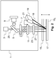
- FIG. 2 schematically illustrates the laser head 1 according to the second embodiment of the present invention.
- the laser head according to the second embodiment is rather similar to the laser head of the first embodiment, but in the present embodiment, the second mirror is not needed.
- the distance sensor 19 is placed laterally on one side of the first optical element 11 and/or the second optical element 23. In this manner it can be placed sufficiently close to the target surface 17.
- the distance between the sensor measurement area and the treatment area i.e., the target surface
- the laser source 3 is in this embodiment aligned with the processing laser beam 25 and the engraving laser beam 27.
- the present invention proposes a laser processing head 1 allowing a real-time or substantially real-time adjustment of the focal points of the engraving beams 27, i.e., a real-time optical focus of multiple beams.
- the proposed solution is especially suitable for laser treatment of transparent conductive coatings in an assembled double/triple/curved, etc. glazing unit.
- a high transmittance for electromagnetic waves in the mobile communication spectrum can be achieved, while maintaining a low thermal emissivity, which is necessary for good thermal insulation by removing a small percentage of the total surface area of the coating, i.e., advantageously less than 20% or more specifically less than 5% of the total surface area.
- the teachings of the present invention may also be used for any other laser treatment, such as marking, engraving, etc. (e.g. a photovoltaic laser fired contact).
- the distance measurement is performed with a fast response time, e.g. up to 200 kHz, in close vicinity of the laser treatment region, which is at least partially defined by the target surface, and which can be achieved through one or more transparent layers 15 1 , 15 2 , i.e. the windowpanes.
- the beam splitter 7 is advantageously rotated to follow the direction of movement of the laser head 1.
- This can be implemented for example so that the wavefront formed by the engraving laser beams is at an acute angle with respect to the movement direction of the laser head 1.
- the angle may for instance be substantially 90°.
- the wavefront would be substantially orthogonal to the direction of movement of the laser head 1.
- a data communication link may also be provided between the first optical focusing element 11 and the motion system so that the first optical focusing element may be rotated based on the movement information received from the motion system.
- the laser head 1 composed of the above-cited components can be rotated to follow a curved or tilted surface.
- the present invention according to one example has the following elements or features:
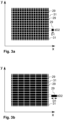
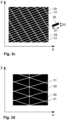
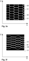
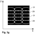
- Figures 3a to 3g illustrate examples of different engraved patterns for the structured coating 17.
- the patterns are illustrated in the examples of Figures 3a to 3g in a coordinate system, where the x-axis represents the horizontal axis (with respect to the ground), and the y-axis represents an axis which is orthogonal to the x-axis and follows the surface of the coating or more specifically the surface of a coating patch 29.
- the y-axis is a vertical axis.
- D1 denotes a first dimension D1, which in this example is parallel to the x-axis
- D2 denotes a second, orthogonal dimension, which in this example is parallel to the y-axis.
- the black regions correspond to the coating patches 29, while the white regions show trenches 31, channels, or ditches made to the respective coating by the engraving process.
- a laser-structured coating can be obtained, where the thermal emissivity of the coating is preferably at most approximately 20%, or more specifically at most approximately 15%.
- the trenches extend cross-sectionally through the coating, and thus the trenches reach the surface of the layer underneath.
- the trenches thus electrically separate different electrically conductive cells, patches or regions formed in the coating from each other.
- the ablated area i.e., the surface area of the trenches 31
- the ablated area is kept small thanks to very narrow ablated lines. Furthermore, as the lines are very small, the structure is hardly seen by the naked eye in most situations. It has been discovered that good results are obtained if the patches are separated from each other by a distance in the range of 0.001 mm to 0.5 mm, and more specifically by distance in the range of 0.01 mm to 0.1 mm.
- a length or a length projection of one or more patches 29 along a first axis is greater than a height or a height projection of the one or more patches 29 along a second, different axis, wherein the first axis substantially horizontally follows a respective patch surface or its virtual extension, and the second axis follows the respective patch surface or its virtual extension orthogonally to the first axis.
- the first axis may be a horizontal axis, and the second axis may be a vertical axis.
- Figure 3a shows patches 29 that have a square shape. Instead, or in addition, the patches could have other regular shapes, such as triangles or circles. As can be seen in Figures 3b to 3g , the patches 29 are in these examples made elongated and they thus define a longitudinal axis along which the patches 29 extend (for instance, in the example of Figure 3b , the length axis is parallel to the x-axis). In other words, their first dimension D1 is greater than a second, orthogonal or substantially orthogonal dimension D2.
- the first dimension D1 extends along the x-axis, which in this example is a horizontal axis
- the second dimension D2 extends along the y-axis, which is orthogonal to the x-axis, and is often a vertical axis, but not always (in particular when the coating 17 is not oriented vertically but would be curved or tilted with respect to the vertical orientation).
- Both the x-axis and y-axis are parallel to the coated surface.
- the first and second dimensions may thus be understood to extend tangentially along the patch surface.
- the patches 29 are rectangles, and more specifically elongated rectangles, while in the design of Figure 3c , the patches 29 are tilted elongated rectangles or they could be rhomboids.
- the patches 29 are triangles, while in the design of Figure 3e , the patches 29 are hexagons, and more specifically non-regular or elongated hexagons.
- waveforms are used to create the patches 29 while in Figure 3g , oval shapes are used to create the patches 29. More specifically, in the design of Figure 3f , first waveforms cross second waveforms to create patches of different sizes. In the design of Figure 3g , partially overlapping ovals are used to create patches of different sizes.
- the patch length/height ratio may be between 1 to 20, or more specifically between 1 and 8, or 1.5 and 8. Furthermore, at least some of the patches have a length in the range of 0.5 mm to 20 mm, and more specifically in the range of 0.5 mm to 10 mm, or in the range of 0.5 mm to 5 mm.
- the trajectory of the laser head is advantageously pre-programmed depending on the desired pattern shape.
- the ditch lines that are parallel to each other can be first engraved with one or more laser head movements, and then the laser head may be reoriented, for instance by rotating it by 90 degrees (or by any desired amount) to engrave ditch lines having a different orientation.
Landscapes
- Physics & Mathematics (AREA)
- Optics & Photonics (AREA)
- Engineering & Computer Science (AREA)
- Plasma & Fusion (AREA)
- Mechanical Engineering (AREA)
- Laser Beam Processing (AREA)
Claims (15)
- Un dispositif de gravure au laser (1) pour graver une surface cible (17), le dispositif de gravure au laser (1) comprenant :- un diviseur de faisceau (7) pour diviser un faisceau laser de traitement (25) en une pluralité de faisceaux laser de gravure (27) ; et- un premier élément de focalisation optique (11) avec un point focal ajustable pour focaliser la pluralité de faisceaux laser de gravure (27) sur la surface cible (17),le dispositif de gravure au laser (1) étant caractérisé en ce qu'il comprend :- un capteur optique (19) configuré pour déterminer la distance entre la surface cible (17) et le capteur optique (19),dans lequel le premier élément de focalisation optique (11) est connecté au capteur optique (19) par une liaison de données (21), qui est une connexion de données filaire ou une connexion de données sans fil, pour recevoir la distance déterminée du capteur optique (19), et dans lequel le capteur optique (19) est configuré pour déterminer la distance à des intervalles de temps de mesure donnés, et le premier élément de focalisation optique (11) est configuré pour ajuster son point focal à des intervalles de temps d'ajustement donnés sur la base de la distance déterminée reçue du capteur optique (19).
- Le dispositif de gravure au laser (1) selon la revendication 1, dans lequel l'intervalle de temps de mesure et/ou l'intervalle de temps d'ajustement est d'au plus 20 µs, ou plus spécifiquement d'au plus 10 µs, ou d'au plus 3 µs, et dans lequel le capteur optique (19) est configuré pour fournir les valeurs de distance déterminées au premier élément de focalisation optique (11) via la liaison de données (21).
- Le dispositif de gravure au laser (1) selon l'une quelconque des revendications précédentes, dans lequel le dispositif de gravure au laser (1) comprend en outre un second élément de focalisation optique (23) placé dans le trajet de la pluralité des faisceaux laser de gravure (27), et configuré pour focaliser la pluralité des faisceaux laser de gravure (27) sur un plan, et/ou dans lequel le capteur optique (19) est un capteur de distance optique ou un capteur de déplacement optique.
- Le dispositif de gravure au laser (1) selon l'une quelconque des revendications précédentes, dans lequel le dispositif de gravure au laser (1) comprend en outre un premier miroir (5), et dans lequel le premier miroir (5) est un miroir dichroïque (5) configuré pour rediriger le faisceau laser de traitement entrant (25) vers le diviseur de faisceau (7), tout en permettant à une lumière réfléchie par la surface cible (17) de passer à travers le miroir dichroïque (5) sans le rediriger, ou le miroir dichroïque (5) est configuré pour rediriger le faisceau laser réfléchi à partir de la surface cible (17), tout en permettant au faisceau laser de traitement entrant (25) de passer à travers le miroir dichroïque (5) sans le rediriger.
- Le dispositif de gravure au laser (1) selon l'une quelconque des revendications précédentes, dans lequel le dispositif de gravure au laser (1) comprend en outre un système de vision (9) placé dans le trajet d'un faisceau laser réfléchi par la surface cible (17), et/ou dans lequel le dispositif de gravure au laser (1) est configuré pour être tourné autour d'un ou plusieurs axes de rotation et/ou se déplacer dans une ou plusieurs directions.
- Le dispositif de gravure au laser (1) selon l'une quelconque des revendications précédentes, dans lequel le premier élément de focalisation optique (11) est configuré pour être tourné autour d'un ou plusieurs axes de rotation.
- Le dispositif de gravure au laser (1) selon la revendication 6, dans lequel la direction de rotation dépend de la direction de déplacement du dispositif de gravure au laser (1), et/ou dans lequel le premier élément de focalisation optique (11) est configuré pour être tourné de sorte qu'un front d'onde formé par au moins certains des faisceaux laser de gravure (27) est à un angle aigu par rapport à la direction de déplacement du dispositif de gravure au laser (1).
- Le dispositif de gravure au laser (1) selon l'une quelconque des revendications précédentes, dans lequel le capteur optique (19) est configuré pour déterminer la distance jusqu'à la surface cible (17) à travers une ou plusieurs surfaces intermédiaires placées entre le capteur optique (19) et la surface cible (17) pour permettre à l'élément de focalisation optique (11) de focaliser la pluralité de faisceaux laser de gravure (27) sur la surface cible (17) à travers les une ou plusieurs surfaces intermédiaires.
- Le dispositif de gravure au laser (1) selon l'une quelconque des revendications précédentes, dans lequel le capteur optique (19) est configuré pour déterminer de manière répétée auxdits intervalles de temps de mesure donnés la distance entre la surface cible (17) et le capteur optique (19), dans lequel le premier élément de focalisation optique (11) est configuré pour recevoir de manière répétée auxdits intervalles de temps de mesure donnés la distance déterminée du capteur optique (19), et dans lequel le premier élément de focalisation optique (11) est configuré pour ajuster de manière répétée auxdits intervalles de temps d'ajustement donnés son point focal sur la base de la distance déterminée reçue du capteur optique (19).
- Le dispositif de gravure au laser (1) selon l'une quelconque des revendications précédentes, dans lequel le nombre de faisceaux laser de gravure (27) est compris entre 2 et 20, ou plus spécifiquement entre 6 et 10, et dans lequel les faisceaux laser de gravure (27) sont agencés dans un réseau de matrices de faisceaux M × N, où au moins M ou N est supérieur à 1, ou où M et N sont tous deux supérieurs à 1.
- Le dispositif de gravure au laser (1) selon l'une quelconque des revendications précédentes, dans lequel le capteur optique (19) est configuré pour générer un ou plusieurs faisceaux de mesure (18) ayant une première longueur d'onde, et dans lequel la première longueur d'onde est différente d'une seconde longueur d'onde des faisceaux laser de gravure (27), et/ou dans lequel le dispositif de gravure au laser (1) comprend en outre une source laser (3) configurée pour générer le faisceau laser de traitement (25).
- Le dispositif de gravure au laser (1) selon l'une quelconque des revendications précédentes, dans lequel le dispositif de gravure au laser (1) est programmé pour se déplacer le long d'une ou plusieurs trajectoires pour permettre à des pièces allongées (29) d'être formées sur la surface cible (17) de sorte que les pièces allongées (29) soient isolées électriquement les unes des autres en conséquence du processus de gravure.
- Le dispositif de gravure au laser (1) selon l'une quelconque des revendications précédentes, dans lequel la zone de mesure de capteur optique est située dans au plus 20 mm, ou plus spécifiquement dans au plus 10 mm de la surface cible (17).
- Un système de gravure au laser comprenant le dispositif de gravure au laser (1) selon l'une quelconque des revendications précédentes, et comprenant en outre un système de mouvement configuré pour déplacer le dispositif de gravure au laser (1) le long d'une ou plusieurs trajectoires et/ou pour faire tourner le dispositif de gravure au laser (1) autour d'un ou plusieurs axes de rotation, et dans lequel le système de gravure au laser comprend en outre une unité de vitrage comprenant une ou plusieurs fenêtres transparentes (151, 152) et la surface cible (17) en tant que partie d'un revêtement électriquement conducteur de l'unité de vitrage.
- Un procédé de gravure d'une surface cible (17) en utilisant un dispositif de gravure au laser (1), le procédé étant caractérisé ce qui suit :- un diviseur de faisceau (7) pour diviser un faisceau laser de traitement (25) en une pluralité de faisceaux laser de gravure (27) ;- un premier élément de focalisation optique (11) avec un point focal ajustable pour focaliser la pluralité de faisceaux laser de gravure (27) sur la surface cible (17) ; et- un capteur optique (19) configuré pour déterminer à des intervalles de temps de mesure donnés la distance entre la surface cible (17) et le capteur optique (19),dans lequel le premier élément de focalisation optique (11) est connecté au capteur optique (19) par une liaison de données (21), qui est une connexion de données filaire ou une connexion de données sans fil, pour recevoir la distance déterminée du capteur optique (19), et le premier élément de focalisation optique (11) est configuré pour ajuster son point focal sur la base de la distance déterminée reçue du capteur optique (19), et dans lequel le procédé comprend :- générer le faisceau laser de traitement (25) ;- diriger le faisceau laser de traitement généré (25) vers le diviseur de faisceau (7) ; et- déplacer le dispositif de gravure au laser (1) le long d'une ou plusieurs trajectoires préprogrammées pour permettre à un motif souhaité d'être formé sur la surface cible (17) suite au processus de gravure tout en ajustant le point focal du premier élément de focalisation optique (11) à des intervalles de temps d'ajustement donnés sur la base de la distance déterminée reçue du capteur optique (19).
Applications Claiming Priority (1)
| Application Number | Priority Date | Filing Date | Title |
|---|---|---|---|
| PCT/IB2020/062269 WO2022136905A1 (fr) | 2020-12-21 | 2020-12-21 | Dispositif de gravure au laser pour de multiples faisceaux laser faisant appel à une liaison de données pour ajuster la position de focalisation |
Publications (3)
| Publication Number | Publication Date |
|---|---|
| EP4263111A1 EP4263111A1 (fr) | 2023-10-25 |
| EP4263111B1 true EP4263111B1 (fr) | 2025-03-26 |
| EP4263111C0 EP4263111C0 (fr) | 2025-03-26 |
Family
ID=74003842
Family Applications (1)
| Application Number | Title | Priority Date | Filing Date |
|---|---|---|---|
| EP20829029.6A Active EP4263111B1 (fr) | 2020-12-21 | 2020-12-21 | Dispositif de gravure au laser pour de multiples faisceaux laser faisant appel à une liaison de données pour ajuster la position de focalisation |
Country Status (3)
| Country | Link |
|---|---|
| US (1) | US20240269776A1 (fr) |
| EP (1) | EP4263111B1 (fr) |
| WO (1) | WO2022136905A1 (fr) |
Families Citing this family (1)
| Publication number | Priority date | Publication date | Assignee | Title |
|---|---|---|---|---|
| CN119525771B (zh) * | 2025-01-20 | 2025-05-02 | 湖南兵器光电科技有限公司 | 一种自适应高能激光模块、破拆装置及破拆方法 |
Family Cites Families (3)
| Publication number | Priority date | Publication date | Assignee | Title |
|---|---|---|---|---|
| US7284396B2 (en) * | 2005-03-01 | 2007-10-23 | International Gemstone Registry Inc. | Method and system for laser marking in the volume of gemstones such as diamonds |
| JP6970580B2 (ja) * | 2017-10-03 | 2021-11-24 | 株式会社ディスコ | レーザ加工装置及び出力確認方法 |
| JP7115973B2 (ja) * | 2018-12-28 | 2022-08-09 | 株式会社キーエンス | レーザ加工装置 |
-
2020
- 2020-12-21 US US18/268,559 patent/US20240269776A1/en active Pending
- 2020-12-21 WO PCT/IB2020/062269 patent/WO2022136905A1/fr not_active Ceased
- 2020-12-21 EP EP20829029.6A patent/EP4263111B1/fr active Active
Also Published As
| Publication number | Publication date |
|---|---|
| EP4263111A1 (fr) | 2023-10-25 |
| WO2022136905A1 (fr) | 2022-06-30 |
| US20240269776A1 (en) | 2024-08-15 |
| EP4263111C0 (fr) | 2025-03-26 |
Similar Documents
| Publication | Publication Date | Title |
|---|---|---|
| US12378157B2 (en) | Apparatus for removing at least one portion of at least one coating system presenting a multi-glazed window and associated method | |
| KR100593721B1 (ko) | 방사선을 반사하는 코팅과 고주파 방사선이 투과하는 창을 구비한 투명 시트 | |
| EP2831542B1 (fr) | Mesure coaxiale de distance par pliage de trajet d'optique de capteur à triangulation | |
| US20240409454A1 (en) | System and associated methods | |
| US20210025984A1 (en) | Glass windows for lidar applications | |
| EP4251365B1 (fr) | Appareil de décapage et procédé associé pour décaper au moins partiellement une partie d'un système de revêtement présent sur une surface d'une fenêtre montée en situ | |
| US20230415271A1 (en) | Laser apparatus comprising a closing means and associated method and use | |
| US20230405724A1 (en) | Method of calibrating a focal point of a laser apparatus mounted on a window mounted in situ | |
| US20240001483A1 (en) | Laser apparatus mounted on a window mounted in situ comprising a skirt and associated method and use | |
| EP4263111B1 (fr) | Dispositif de gravure au laser pour de multiples faisceaux laser faisant appel à une liaison de données pour ajuster la position de focalisation | |
| US20250135575A1 (en) | Laser device and its use and method for processing a glass sheet | |
| TW201943557A (zh) | 使用菲涅爾波帶片透鏡以放大微波反射窗所衰減的微波訊號 | |
| RU2610079C2 (ru) | Демпфирующее радиолокационное отражение остекление | |
| EP4115042B1 (fr) | Unité de vitrage | |
| CN103116200A (zh) | 基于窄带干涉滤光片和主动标志器实现的适配系统 | |
| WO2024052879A1 (fr) | Revêtement contre le rayonnement solaire optimisé par ablation par laser | |
| EP4587397A1 (fr) | Procédés de décapage | |
| WO2025046119A1 (fr) | Appareil de décapage et procédés et utilisation associés | |
| EP4587396A1 (fr) | Procédés de décapage | |
| WO2025068129A1 (fr) | Système comprenant un appareil de décapage, et procédés et utilisation associés | |
| CN120835867A (zh) | 具有通信窗口的涂覆面板 | |
| EP4587395A1 (fr) | Unité de vitrage et procédé de décapage associé | |
| WO2024251624A1 (fr) | Appareil de décapage et procédés associés pour décaper une partie d'un revêtement sur une fenêtre | |
| CN120583667A (zh) | 一种消除下滑信标多径干扰的电磁谐振结构 | |
| HK1206809B (en) | Coaxial distance measurement via folding of triangulation sensor optics path |
Legal Events
| Date | Code | Title | Description |
|---|---|---|---|
| STAA | Information on the status of an ep patent application or granted ep patent |
Free format text: STATUS: UNKNOWN |
|
| STAA | Information on the status of an ep patent application or granted ep patent |
Free format text: STATUS: THE INTERNATIONAL PUBLICATION HAS BEEN MADE |
|
| PUAI | Public reference made under article 153(3) epc to a published international application that has entered the european phase |
Free format text: ORIGINAL CODE: 0009012 |
|
| STAA | Information on the status of an ep patent application or granted ep patent |
Free format text: STATUS: REQUEST FOR EXAMINATION WAS MADE |
|
| 17P | Request for examination filed |
Effective date: 20230630 |
|
| AK | Designated contracting states |
Kind code of ref document: A1 Designated state(s): AL AT BE BG CH CY CZ DE DK EE ES FI FR GB GR HR HU IE IS IT LI LT LU LV MC MK MT NL NO PL PT RO RS SE SI SK SM TR |
|
| DAV | Request for validation of the european patent (deleted) | ||
| DAX | Request for extension of the european patent (deleted) | ||
| GRAP | Despatch of communication of intention to grant a patent |
Free format text: ORIGINAL CODE: EPIDOSNIGR1 |
|
| STAA | Information on the status of an ep patent application or granted ep patent |
Free format text: STATUS: GRANT OF PATENT IS INTENDED |
|
| INTG | Intention to grant announced |
Effective date: 20240807 |
|
| GRAJ | Information related to disapproval of communication of intention to grant by the applicant or resumption of examination proceedings by the epo deleted |
Free format text: ORIGINAL CODE: EPIDOSDIGR1 |
|
| STAA | Information on the status of an ep patent application or granted ep patent |
Free format text: STATUS: REQUEST FOR EXAMINATION WAS MADE |
|
| INTC | Intention to grant announced (deleted) | ||
| GRAP | Despatch of communication of intention to grant a patent |
Free format text: ORIGINAL CODE: EPIDOSNIGR1 |
|
| STAA | Information on the status of an ep patent application or granted ep patent |
Free format text: STATUS: GRANT OF PATENT IS INTENDED |
|
| RAP3 | Party data changed (applicant data changed or rights of an application transferred) |
Owner name: ECOLE POLYTECHNIQUE FEDERALE DE LAUSANNE(EPFL) |
|
| INTG | Intention to grant announced |
Effective date: 20241212 |
|
| GRAS | Grant fee paid |
Free format text: ORIGINAL CODE: EPIDOSNIGR3 |
|
| GRAA | (expected) grant |
Free format text: ORIGINAL CODE: 0009210 |
|
| STAA | Information on the status of an ep patent application or granted ep patent |
Free format text: STATUS: THE PATENT HAS BEEN GRANTED |
|
| AK | Designated contracting states |
Kind code of ref document: B1 Designated state(s): AL AT BE BG CH CY CZ DE DK EE ES FI FR GB GR HR HU IE IS IT LI LT LU LV MC MK MT NL NO PL PT RO RS SE SI SK SM TR |
|
| REG | Reference to a national code |
Ref country code: GB Ref legal event code: FG4D |
|
| REG | Reference to a national code |
Ref country code: CH Ref legal event code: EP |
|
| REG | Reference to a national code |
Ref country code: DE Ref legal event code: R096 Ref document number: 602020048436 Country of ref document: DE |
|
| REG | Reference to a national code |
Ref country code: IE Ref legal event code: FG4D |
|
| U01 | Request for unitary effect filed |
Effective date: 20250326 |
|
| U07 | Unitary effect registered |
Designated state(s): AT BE BG DE DK EE FI FR IT LT LU LV MT NL PT RO SE SI Effective date: 20250401 |
|
| PG25 | Lapsed in a contracting state [announced via postgrant information from national office to epo] |
Ref country code: RS Free format text: LAPSE BECAUSE OF FAILURE TO SUBMIT A TRANSLATION OF THE DESCRIPTION OR TO PAY THE FEE WITHIN THE PRESCRIBED TIME-LIMIT Effective date: 20250626 |
|
| PG25 | Lapsed in a contracting state [announced via postgrant information from national office to epo] |
Ref country code: NO Free format text: LAPSE BECAUSE OF FAILURE TO SUBMIT A TRANSLATION OF THE DESCRIPTION OR TO PAY THE FEE WITHIN THE PRESCRIBED TIME-LIMIT Effective date: 20250626 |
|
| PG25 | Lapsed in a contracting state [announced via postgrant information from national office to epo] |
Ref country code: HR Free format text: LAPSE BECAUSE OF FAILURE TO SUBMIT A TRANSLATION OF THE DESCRIPTION OR TO PAY THE FEE WITHIN THE PRESCRIBED TIME-LIMIT Effective date: 20250326 |
|
| PG25 | Lapsed in a contracting state [announced via postgrant information from national office to epo] |
Ref country code: GR Free format text: LAPSE BECAUSE OF FAILURE TO SUBMIT A TRANSLATION OF THE DESCRIPTION OR TO PAY THE FEE WITHIN THE PRESCRIBED TIME-LIMIT Effective date: 20250627 |
|
| PG25 | Lapsed in a contracting state [announced via postgrant information from national office to epo] |
Ref country code: SM Free format text: LAPSE BECAUSE OF FAILURE TO SUBMIT A TRANSLATION OF THE DESCRIPTION OR TO PAY THE FEE WITHIN THE PRESCRIBED TIME-LIMIT Effective date: 20250326 |
|
| PG25 | Lapsed in a contracting state [announced via postgrant information from national office to epo] |
Ref country code: ES Free format text: LAPSE BECAUSE OF FAILURE TO SUBMIT A TRANSLATION OF THE DESCRIPTION OR TO PAY THE FEE WITHIN THE PRESCRIBED TIME-LIMIT Effective date: 20250326 |
|
| PG25 | Lapsed in a contracting state [announced via postgrant information from national office to epo] |
Ref country code: PL Free format text: LAPSE BECAUSE OF FAILURE TO SUBMIT A TRANSLATION OF THE DESCRIPTION OR TO PAY THE FEE WITHIN THE PRESCRIBED TIME-LIMIT Effective date: 20250326 |
|
| PG25 | Lapsed in a contracting state [announced via postgrant information from national office to epo] |
Ref country code: SK Free format text: LAPSE BECAUSE OF FAILURE TO SUBMIT A TRANSLATION OF THE DESCRIPTION OR TO PAY THE FEE WITHIN THE PRESCRIBED TIME-LIMIT Effective date: 20250326 |
|
| PG25 | Lapsed in a contracting state [announced via postgrant information from national office to epo] |
Ref country code: IS Free format text: LAPSE BECAUSE OF FAILURE TO SUBMIT A TRANSLATION OF THE DESCRIPTION OR TO PAY THE FEE WITHIN THE PRESCRIBED TIME-LIMIT Effective date: 20250726 |
|
| U20 | Renewal fee for the european patent with unitary effect paid |
Year of fee payment: 6 Effective date: 20251125 |
|
| REG | Reference to a national code |
Ref country code: CH Ref legal event code: U11 Free format text: ST27 STATUS EVENT CODE: U-0-0-U10-U11 (AS PROVIDED BY THE NATIONAL OFFICE) Effective date: 20260101 |
|
| PGFP | Annual fee paid to national office [announced via postgrant information from national office to epo] |
Ref country code: GB Payment date: 20251121 Year of fee payment: 6 |
|
| PG25 | Lapsed in a contracting state [announced via postgrant information from national office to epo] |
Ref country code: CZ Free format text: LAPSE BECAUSE OF FAILURE TO SUBMIT A TRANSLATION OF THE DESCRIPTION OR TO PAY THE FEE WITHIN THE PRESCRIBED TIME-LIMIT Effective date: 20250326 |
|
| PLBE | No opposition filed within time limit |
Free format text: ORIGINAL CODE: 0009261 |
|
| STAA | Information on the status of an ep patent application or granted ep patent |
Free format text: STATUS: NO OPPOSITION FILED WITHIN TIME LIMIT |
|
| REG | Reference to a national code |
Ref country code: CH Ref legal event code: L10 Free format text: ST27 STATUS EVENT CODE: U-0-0-L10-L00 (AS PROVIDED BY THE NATIONAL OFFICE) Effective date: 20260211 |
|
| 26N | No opposition filed |
Effective date: 20260105 |
|
| PGFP | Annual fee paid to national office [announced via postgrant information from national office to epo] |
Ref country code: CH Payment date: 20260101 Year of fee payment: 6 |