EP4263346B1 - Flugzeugradbremsvorrichtung - Google Patents
Flugzeugradbremsvorrichtung Download PDFInfo
- Publication number
- EP4263346B1 EP4263346B1 EP21836578.1A EP21836578A EP4263346B1 EP 4263346 B1 EP4263346 B1 EP 4263346B1 EP 21836578 A EP21836578 A EP 21836578A EP 4263346 B1 EP4263346 B1 EP 4263346B1
- Authority
- EP
- European Patent Office
- Prior art keywords
- torque tube
- braking device
- heat shield
- retaining tabs
- tubular body
- Prior art date
- Legal status (The legal status is an assumption and is not a legal conclusion. Google has not performed a legal analysis and makes no representation as to the accuracy of the status listed.)
- Active
Links
Images



Classifications
-
- B—PERFORMING OPERATIONS; TRANSPORTING
- B64—AIRCRAFT; AVIATION; COSMONAUTICS
- B64C—AEROPLANES; HELICOPTERS
- B64C25/00—Alighting gear
- B64C25/32—Alighting gear characterised by elements which contact the ground or similar surface
- B64C25/42—Arrangement or adaptation of brakes
-
- B—PERFORMING OPERATIONS; TRANSPORTING
- B60—VEHICLES IN GENERAL
- B60B—VEHICLE WHEELS; CASTORS; AXLES FOR WHEELS OR CASTORS; INCREASING WHEEL ADHESION
- B60B7/00—Wheel cover discs, rings, or the like, for ornamenting, protecting, venting, or obscuring, wholly or in part, the wheel body, rim, hub, or tyre sidewall, e.g. wheel cover discs, wheel cover discs with cooling fins
- B60B7/01—Rings specially adapted for covering only the wheel rim or the tyre sidewall, e.g. removable tyre sidewall trim rings
-
- B—PERFORMING OPERATIONS; TRANSPORTING
- B60—VEHICLES IN GENERAL
- B60T—VEHICLE BRAKE CONTROL SYSTEMS OR PARTS THEREOF; BRAKE CONTROL SYSTEMS OR PARTS THEREOF, IN GENERAL; ARRANGEMENT OF BRAKING ELEMENTS ON VEHICLES IN GENERAL; PORTABLE DEVICES FOR PREVENTING UNWANTED MOVEMENT OF VEHICLES; VEHICLE MODIFICATIONS TO FACILITATE COOLING OF BRAKES
- B60T5/00—Vehicle modifications to facilitate cooling of brakes
-
- B—PERFORMING OPERATIONS; TRANSPORTING
- B64—AIRCRAFT; AVIATION; COSMONAUTICS
- B64C—AEROPLANES; HELICOPTERS
- B64C25/00—Alighting gear
- B64C25/32—Alighting gear characterised by elements which contact the ground or similar surface
- B64C25/34—Alighting gear characterised by elements which contact the ground or similar surface wheeled type, e.g. multi-wheeled bogies
- B64C25/36—Arrangements or adaptations of wheels, tyres or axles in general
-
- F—MECHANICAL ENGINEERING; LIGHTING; HEATING; WEAPONS; BLASTING
- F16—ENGINEERING ELEMENTS AND UNITS; GENERAL MEASURES FOR PRODUCING AND MAINTAINING EFFECTIVE FUNCTIONING OF MACHINES OR INSTALLATIONS; THERMAL INSULATION IN GENERAL
- F16D—COUPLINGS FOR TRANSMITTING ROTATION; CLUTCHES; BRAKES
- F16D65/00—Parts or details
- F16D65/78—Features relating to cooling
- F16D65/84—Features relating to cooling for disc brakes
- F16D65/847—Features relating to cooling for disc brakes with open cooling system, e.g. cooled by air
-
- B—PERFORMING OPERATIONS; TRANSPORTING
- B60—VEHICLES IN GENERAL
- B60B—VEHICLE WHEELS; CASTORS; AXLES FOR WHEELS OR CASTORS; INCREASING WHEEL ADHESION
- B60B2900/00—Purpose of invention
- B60B2900/50—Improvement of
- B60B2900/513—Cooling, e.g. of brakes
-
- F—MECHANICAL ENGINEERING; LIGHTING; HEATING; WEAPONS; BLASTING
- F16—ENGINEERING ELEMENTS AND UNITS; GENERAL MEASURES FOR PRODUCING AND MAINTAINING EFFECTIVE FUNCTIONING OF MACHINES OR INSTALLATIONS; THERMAL INSULATION IN GENERAL
- F16D—COUPLINGS FOR TRANSMITTING ROTATION; CLUTCHES; BRAKES
- F16D65/00—Parts or details
- F16D65/78—Features relating to cooling
- F16D2065/785—Heat insulation or reflection
Definitions
- the present invention relates to the field of braking and more particularly to the control of heat transfers during braking.
- An aircraft landing gear generally comprises a leg having a first end connected to a structure of the aircraft and a second end provided with a shaft or axle on which a wheel is rotatably mounted.
- the wheel comprises a rim connected by a web to a hub which receives the shaft of the leg by means of bearings and which defines with the rim a space in which a stack of brake disks is arranged.
- the stack of disks comprises alternately stator disks immobilized in rotation on a torque tube coaxial with the hub of the wheel and rotor disks integral in rotation with the rim of the wheel.
- Actuators for example hydraulic cylinders, are arranged to exert a pressing force on the stack of disks via a hydraulic crown so as to brake the wheel.
- the heat generated by friction between the discs can be significant (particularly when the aircraft lands, where the energy to be dissipated is at its maximum due to the mass and high speed of the aircraft at the time of landing) and can lead to overheating of the brake and its environment. This problem is addressed in particular in the document EP-A-3702275 .
- Some heat shields extend from the wheel web to an internal shoulder of the torque tube forming a tube foot onto which the heat shields are screwed to hold them in position inside the torque tube.
- heat shields have one end sandwiched between the hydraulic crown and a bottom of the torque tube, and an opposite end secured to a free edge of the torque tube by screwing via a connecting piece. These heat shields extend over the entire length of the torque tube, which tends to increase the heating of said torque tube. What is more, the existence of the connecting piece connecting the heat shield to the free edge of the torque tube has the effect of increasing the cost and mass of the assembly.
- the invention therefore aims to propose a heat shield making it possible to at least partially overcome the aforementioned problems.
- the invention proposes a braking device for an aircraft wheel, a hub of which is rotatably mounted on an axle.
- the device comprises a stack of disks threaded onto a torque tube which is intended to be fixed to the axle and internally equipped with a heat shield intended to extend opposite an outer surface of the hub facing the stack of disks to protect said hub from thermal radiation generated by the stack of disks.
- the heat shield comprises a tubular body coaxial with the torque tube and a plurality of elastically deformable retaining tabs secured to the tubular body, each of the retaining tabs and an inner surface of the torque tube comprising complementary reliefs to cooperate together so as to axially immobilize the heat shield inside the torque tube.
- the heat shield is thus elastically retained in the torque tube.
- the retaining tabs therefore allow tool-free assembly of the heat shield inside the torque tube and also reduce assembly time while limiting the cost and mass of the assembly.
- the tubular body is intended to extend from a veil of the wheel and a free edge of the hub.
- the heat shield only partially covers the inner surface of the torque tube, which tends to limit the heating of said torque tube during braking.
- the tubular body comprises stampings in the form of spherical caps facing the inner surface of the torque tube to form point contacts with said inner surface of the tube.
- stampings ensure the mechanical strength of the heat shield while limiting thermal conduction between the main body and the torque tube.
- the holding legs are equally distributed around the central axis of the tubular body.
- the inner surface of the torque tube comprises a radially projecting step and each of the retaining tabs has a relief for hooking said step and, preferably, at least one of the retaining tabs comprises a transverse groove arranged to simultaneously cooperate with a front face and a rear face of the step.
- the groove has a depth less than a height of the step such that said retaining tab is detached from the inner surface of the torque tube limiting thermal conduction between the screen and the torque tube.
- At least one of the retaining tabs comprises an inclined terminal portion forming a ramp on which the step rests and slides when the heat shield is introduced into the torque tube, causing the elastic deformation of the retaining tab until the step passes.
- the retaining tabs define a diameter less than an inner diameter of the torque tube and greater than the outer diameter of the tubular body.
- At least one of the support legs is integral with the main body.
- the invention also relates to an aircraft wheel equipped with such a braking device.
- the invention also relates to an aircraft landing gear comprising at least one such wheel.
- the invention further relates to an aircraft equipped with such landing gear.
- the invention is described here in application to an aircraft comprising at least one main landing gear having a leg of which a first end is articulated to a structure of the aircraft and a second end is provided with an axle on which at least one wheel is rotatably mounted.
- the invention relates to a braking device, generally designated 1, equipping the wheel 2 of the main landing gear of the aircraft.
- the wheel 2 comprises two half-wheels 2a, 2b which each comprise an annular rim 3a, 3b connected by a web 4a, 4b to a half-hub 5a, 5b pivotally received on an axle or spindle 6 by means of a bearing 7, 8.
- the half-wheel 2a comprises a housing provided on an edge of the rim 3a and in which a sealing gasket 9 is arranged so that the latter is elastically compressed between the half-wheels 2a, 2b once they are assembled.
- the half-wheels 2a, 2b are brought together in a direction parallel to an axis X of rotation of the wheel 2 and have centering bearings to ensure the correct relative positioning of the half-wheels 2a, 2b.
- the half-wheels 2a, 2b are held in position by bolts 10 extending into holes drilled opposite each other in the webs 4a, 4b.
- the bolts 10 are screwed and tightened to assemble the half-wheels 2a, 2b after mounting a tire (not shown) on the rims 3a, 3b.
- the seal 9 is elastically compressed between the half-wheels 2a, 2b and thus prevents the gas contained in a volume delimited by the tire and the half-wheels 2a, 2b from escaping to the outside of the wheel 2.
- the braking device 1 comprises brake discs 11, including stator discs 11a and rotor discs 11b, which are stacked alternately against each other on a torque tube 12 fixed to a collar 13 of the axle.
- the torque tube 12 and the stack of discs 11 extend inside the half-wheel 2a in an annular space delimited by an inner surface of the rim 3a, the web 4a and an outer surface of the half-hub 5a extending opposite the inner surface of the rim 3a.
- the stator disks 11a are fixed in rotation relative to the axle 6 and the rotor disks 11b have axial peripheral notches each receiving a section of a bar (not visible in the figure) fixed on the inner surface of the rim 3a.
- the bars extend along an axis parallel to the axis X of rotation of the wheel 2 and ensure a rotational coupling of the rotor disks 11b with the rim 3a around said axis X.
- the braking device 1 further comprises a hydraulic crown 15 fixed to one end of the torque tube 12 by means of screws 16.
- the crown 15 comprises a plurality of cavities 17 distributed here equally around the axis X of rotation of the wheel 2.
- Each of the cavities 17 receives an actuator 18 selectively exerting a braking force against a first stator disk 11a of the stack of disks 11 via a pressurized hydraulic fluid circulating inside the crown 15.
- the ring distribution of the actuators 18 makes it possible to distribute the braking force equally over the entire surface of the first stator disk 11a.
- the braking device 1 is equipped with a tubular heat shield 20 extending coaxially with the torque tube between a cylindrical inner surface 12.1 of said torque tube 12 and an outer surface 5.1 of the half-hub 5a facing the stack of disks 11 to protect said half-hub 5a from the thermal radiation generated by the friction of the disks 11 during braking of the wheel 2.
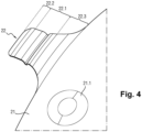
- the heat shield 20 comprises a main body 21 of cylindrical shape having an external diameter slightly smaller than the diameter of the inner surface 12.1 of the torque tube 12.
- the main body 21 extends from the web to a free edge 5.2 of the half-hub 5a so that the heat shield 20 only partially covers the inner surface 12.1 of the torque tube 12.
- the main body 21 comprises a plurality of stampings 21.1 here symmetrically distributed around the central axis of the main body 21.
- the stampings 21.1 are in the form of spherical caps with convexity oriented towards the inner surface 12.1 of the torque tube 12 and form point contacts with said surface inner 12.1 of the torque tube 12 to ensure the mechanical strength of the heat shield 20 while limiting thermal conduction between the main body 21 and the torque tube 12.
- the heat shield 20 also comprises three elastically deformable retaining tabs 22 which bear against an annular step 19 extending radially from the inner surface 12.1 of the torque tube 12 to elastically hold the heat shield 20 in position inside the torque tube 12.
- the step 19 comprises a front face 19.1 and a rear face 19.2 which are both truncated in shape and which are joined by their large base.
- the retaining tabs 22 extend generally in axial projection from one edge of the main body 21 towards the hydraulic crown 15 and are here equally distributed around this edge.
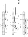
- the retaining tabs 22 are arranged to retract elastically in contact with the step 19 when the heat shield 20 is inserted into the torque tube 12, and to oppose the axial movement of the main body 21 once the heat shield 20 is in position in said torque tube 12.
- the retaining tabs 22 have a generally rectilinear central portion 22.1 provided in its middle with a stamping forming a transverse groove 23 arranged to have sides cooperating simultaneously and respectively with the front face 19.1 and the rear face 19.2 of the step 19, and an inclined terminal portion 22.2 which forms a ramp on which the front face 19.1 of the step 19 rests and slides when the heat shield 20 is inserted into the torque tube 12, causing the elastic deformation of the retaining tabs 22 until let the step 19 pass.
- the sides of the groove 23 and the faces 19.1, 19.2 of the step 19 form with the central axis an angle greater than that formed between the terminal portion 22.2 and said central axis such that the sides of the groove 23 and/or the faces 19.1, 19.2 of the step 19 cannot serve as a ramp facilitating a deformation of the retaining tabs 22 towards the central axis when an axial force is exerted on the heat shield 20.
- the retaining legs 22 also have a connecting portion 22.3 connecting the central portion 22.1 to the edge of the main body 21.
- the groove 23 has a depth less than the height of the step 19 so that the sides of the groove are pressed against the front and rear faces of the step 19 respectively when the heat shield 20 is in position in the torque tube, and that, when the retaining tabs 22 are in a rest state, the central portions 22.1 of the retaining tabs 22 have an outside diameter slightly greater than that of the main body 21 and slightly less than the diameter of the inside surface 12.1 of the torque tube 12, so that the retaining tabs 22 are in contact with the torque tube 12 only at the grooves 23, which makes it possible to limit any damage to the torque tube 12 during its operation.
- the heat shield 20 is first introduced inside the torque tube 12 coaxially therewith until the end portions 22.2 of the retaining tabs 22 come into contact with the front face 19.1 of the step 19 of the torque tube 12.
- the step 19 exerts on the end portions 22.2 a radial force tending to deform the retaining tabs 22 to bring the retaining legs 22 towards the central axis until the step 19 engages in the grooves 23 axially immobilizing the main body 21 inside the torque tube 12.
- the inclination of the terminal portions 22.2 makes it easier to mount the heat shield 20, it will be noted that it also makes it easier to disassemble it. Indeed, the operator can easily deform the retaining tabs by exerting an axial force under the terminal portions 22.2, and thus release the step 19 from the grooves 23 while exerting an extraction force on the heat shield 20.
- FIG 6 illustrates a holding tab 22' which is none other than a variant of the holding tab 22 illustrated in figure 4 .
- the retaining tab 22' differs from the retaining tab 22 in that it includes a stiffener 24 formed by a stamping extending between the edge of the main body 21 and the groove 23 in order to increase its rigidity.
- the heat shield 20 can be made of a thermally insulating material such as steel, stainless steel, titanium, etc.
- the shape, number, distribution and dimensions of the holding legs 22, 22' may differ from those illustrated.
- the retaining tabs 22, 22' may be provided with a step projecting radially outwards to hook behind the step 19. It is possible to provide that the step of certain tabs bears against the front face of the step 19 and that other legs rest against the rear face of the step 19.
- a groove may be provided in the inner surface of the torque tube 12 and the retaining tabs 22, 22' may be provided with a step projecting radially outwards to penetrate into said groove and ensure the immobilization of the heat shield 20 in the torque tube 12.
- the retaining tabs can be cut into the tubular body set back from the edge of the body.
- retaining tabs 22, 22' are integral with the main body 21, they can also be attached to said main body 21.
- the number, shape and location of the stiffener 24 may be different from that illustrated in the figure 6 .
Landscapes
- Engineering & Computer Science (AREA)
- Mechanical Engineering (AREA)
- Aviation & Aerospace Engineering (AREA)
- General Engineering & Computer Science (AREA)
- Transportation (AREA)
- Braking Arrangements (AREA)
Claims (13)
- Bremsvorrichtung (1) für ein Luftfahrzeug-Rad (2) mit einer drehbar auf einer Achse (6) montierten Nabe (5a, 5b), wobei die Vorrichtung einen Scheibenstapel (11) umfasst, der auf ein Torsionsrohr (12) aufgeschoben ist, das dazu bestimmt ist, an der Achse befestigt zu werden, und das innenseitig mit einem Hitzeschild (20) ausgestattet ist, der dazu bestimmt ist, sich einer dem Scheibenstapel zugewandten Außenfläche (5.1) der Nabe gegenüberliegend zu erstrecken, um die Nabe vor einer durch den Scheibenstapel erzeugten Wärmestrahlung zu schützen, wobei der Hitzeschild einen zu dem Torsionsrohr koaxialen, rohrförmigen Körper (21) umfasst, wobei die Bremsvorrichtung dadurch gekennzeichnet ist, dass der Hitzeschild ferner eine Mehrzahl von elastisch verformbaren Haltelaschen (22) umfasst, die fest mit dem rohrförmigen Körper verbunden sind, wobei eine jede der Haltelaschen und eine Innenfläche (12.1) des Torsionsrohrs komplementäre Reliefstrukturen aufweisen, durch deren Zusammenwirken der Hitzeschild axial im Inneren des Torsionsrohrs fest in Position gehalten wird.
- Bremsvorrichtung (1) nach Anspruch 1, wobei der rohrförmige Körper (21) dazu bestimmt ist, sich ausgehend von einer Radscheibe (4a, 4b) des Rades und von einem freien Rand (5.2) der Nabe (5a, 5b) weg zu erstrecken.
- Bremsvorrichtung (1) nach Anspruch 2, wobei der rohrförmige Körper (21) Prägungen (21.1) in Form von Kugelkalotten aufweist, welche der Innenfläche (12.1) des Torsionsrohrs (12) zugewandt sind, um Punktkontakte mit der Innenfläche des Rohrs zu bilden.
- Bremsvorrichtung (1) nach einem der vorhergehenden Ansprüche, wobei die Haltelaschen (22) gleichmäßig um die Mittelachse des rohrförmigen Körpers (21) herum verteilt sind.
- Bremsvorrichtung (1) nach einem der vorhergehenden Ansprüche, wobei die Innenfläche (12.1) des Torsionsrohrs eine radial hervorstehende Stufe (19) umfasst und eine jede der Haltelaschen (22) ein Relief zum Ineingriffbringen mit dieser Stufe umfasst.
- Bremsvorrichtung (1) nach Anspruch 5, wobei zumindest eine der Haltelaschen (22) eine Quernut (23) umfasst, die dafür ausgelegt ist, zugleich mit einer Vorderseite (19.1) und mit einer Rückseite (19.2) der Stufe (19) zusammenzuwirken.
- Bremsvorrichtung (1) nach Anspruch 5 oder nach Anspruch 6, wobei eine Tiefe der Nut (23) geringer ist als eine Höhe der Stufe, sodass die Haltelasche (22) von der Innenfläche des Torsionsrohrs abgehoben ist.
- Bremsvorrichtung (1) nach einem der Ansprüche 5 bis 7, wobei zumindest eine der Haltelaschen (22) einen als Rampe dienenden, geneigten Endabschnitt (22.2) umfasst, auf welchem sich die Stufe (19) abstützt und entlanggleitet, wenn der Hitzeschild (20) in das Torsionsrohr (12) eingeführt wird, wobei die Haltelasche dabei so weit elastisch verformt wird, bis die Stufe hindurchpasst.
- Bremsvorrichtung (1) nach einem der Ansprüche 5 bis 8, wobei die Haltelaschen (22) einen Durchmesser definieren, der kleiner als ein Innendurchmesser des Torsionsrohrs (12) und größer als ein Außendurchmesser des rohrförmigen Körpers (21) ist.
- Bremsvorrichtung (1) nach einem der vorhergehenden Ansprüche, wobei zumindest eine der Haltelaschen (22) einstückig mit dem Hauptkörper (21) ausgebildet ist.
- Luftfahrzeug-Rad (2), das mit einer Bremsvorrichtung (1) nach einem der vorhergehenden Ansprüche ausgestattet ist.
- Luftfahrzeug-Fahrwerk, welches zumindest ein Rad (2) nach Anspruch 11 umfasst.
- Luftfahrzeug, welches zumindest ein Fahrwerk nach Anspruch 12 umfasst.
Applications Claiming Priority (2)
| Application Number | Priority Date | Filing Date | Title |
|---|---|---|---|
| FR2013821A FR3117999B1 (fr) | 2020-12-21 | 2020-12-21 | Dispositif de freinage d’une roue d’aéronef ; roue, train d’atterrissage et aéronef équipés d’un tel dispositif. |
| PCT/EP2021/086887 WO2022136319A1 (fr) | 2020-12-21 | 2021-12-20 | Dispositif de freinage d'une roue d'aeronef |
Publications (2)
| Publication Number | Publication Date |
|---|---|
| EP4263346A1 EP4263346A1 (de) | 2023-10-25 |
| EP4263346B1 true EP4263346B1 (de) | 2025-01-29 |
Family
ID=74669093
Family Applications (1)
| Application Number | Title | Priority Date | Filing Date |
|---|---|---|---|
| EP21836578.1A Active EP4263346B1 (de) | 2020-12-21 | 2021-12-20 | Flugzeugradbremsvorrichtung |
Country Status (5)
| Country | Link |
|---|---|
| US (1) | US20240043114A1 (de) |
| EP (1) | EP4263346B1 (de) |
| CN (1) | CN116802119B (de) |
| FR (1) | FR3117999B1 (de) |
| WO (1) | WO2022136319A1 (de) |
Families Citing this family (4)
| Publication number | Priority date | Publication date | Assignee | Title |
|---|---|---|---|---|
| CN110203380B (zh) * | 2019-07-08 | 2024-02-23 | 西安航空制动科技有限公司 | 一种用于飞机刹车装置的整体式隔热屏 |
| FR3112755B1 (fr) * | 2020-07-21 | 2022-07-29 | Safran Landing Systems | Ensemble d’écran thermique |
| FR3146959B1 (fr) * | 2023-03-22 | 2025-03-14 | Safran Landing Systems | Dispositif de verrouillage axial d’un premier élément tubulaire reçu à ajustement dans un deuxième élément tubulaire |
| US20250319962A1 (en) * | 2024-04-10 | 2025-10-16 | Honeywell International Inc. | Wheel heat shields and techniques for forming wheel heat shields |
Family Cites Families (8)
| Publication number | Priority date | Publication date | Assignee | Title |
|---|---|---|---|---|
| US4856619A (en) * | 1988-06-06 | 1989-08-15 | Loral Corporation | Aircraft wheel drive key and heatshield assembly |
| US5107968A (en) * | 1991-02-12 | 1992-04-28 | The B. F. Goodrich Company | Heatshield for aircraft brake |
| US5248013A (en) * | 1992-02-13 | 1993-09-28 | The B. F. Goodrich Company | Heatshield installation for aircraft brake |
| US5926932A (en) * | 1997-06-06 | 1999-07-27 | Alliedsignal Inc. | Methods of converting aircraft brake assemblies |
| US6095293A (en) * | 1998-02-13 | 2000-08-01 | The B. F. Goodrich Company | Aircraft brake and method with electromechanical actuator modules |
| US8523108B2 (en) * | 2011-03-24 | 2013-09-03 | Goodrich Corporation | Heat shield installation for aircraft wheel to improve convective cooling of aircraft brake |
| US9908375B2 (en) * | 2015-10-20 | 2018-03-06 | Goodrich Corporation | Ventilated key-slot full circle heat shield |
| FR3093321B1 (fr) | 2019-02-28 | 2021-06-18 | Safran Landing Systems | Roue d’aéronef pourvue d’écrans thermiques |
-
2020
- 2020-12-21 FR FR2013821A patent/FR3117999B1/fr active Active
-
2021
- 2021-12-20 WO PCT/EP2021/086887 patent/WO2022136319A1/fr not_active Ceased
- 2021-12-20 EP EP21836578.1A patent/EP4263346B1/de active Active
- 2021-12-20 CN CN202180086766.4A patent/CN116802119B/zh active Active
- 2021-12-20 US US18/268,635 patent/US20240043114A1/en active Pending
Also Published As
| Publication number | Publication date |
|---|---|
| EP4263346A1 (de) | 2023-10-25 |
| US20240043114A1 (en) | 2024-02-08 |
| FR3117999B1 (fr) | 2022-11-11 |
| WO2022136319A1 (fr) | 2022-06-30 |
| CN116802119A (zh) | 2023-09-22 |
| CN116802119B (zh) | 2025-08-26 |
| FR3117999A1 (fr) | 2022-06-24 |
Similar Documents
| Publication | Publication Date | Title |
|---|---|---|
| EP4263346A1 (de) | Flugzeugradbremsvorrichtung | |
| EP1584794B1 (de) | Turbomaschinenrotorscheibe mit einer Axialhalterung für die Laufschaufeln | |
| EP3121481B1 (de) | Vorrichtung zur torsionsschwingungsdämpfung für das antriebssystem eines kraftfahrzeugs | |
| FR2973003A1 (fr) | Dispositif d'obturation a verrouillage auto-activable | |
| FR3039237A1 (fr) | Dispositif de transmission de couple pour un vehicule automobile | |
| EP2691670B1 (de) | Schwungmasse mit verliersicherungsmittel der schrauben zur befestigung an der kurberwelle | |
| CA2472301C (fr) | Dispositif de fixation par vis et ecrous | |
| EP4146537B1 (de) | Hitzeschild für eine bremsvorrichtung eines flugzeugrads | |
| EP0327476A1 (de) | Scheibenbremse für eine rotierende Welle | |
| WO1996035890A1 (fr) | Appareil d'accouplement hydrocinetique, notamment pour vehicule automobile | |
| EP2053199B1 (de) | Rad eines Turbotriebwerks | |
| EP4185528B1 (de) | Hitzeschildanordnung | |
| FR3079573A1 (fr) | Porte-disques pour mecanisme d'embrayage de vehicule automobile et module d'embrayage comprenant un tel porte-disques | |
| FR3068741A1 (fr) | Arbre d’entrainement pour une turbomachine | |
| FR2765937A1 (fr) | Ensemble amortisseur dynamique compact et ensemble formant volant comportant un tel ensemble amortisseur dynamique | |
| EP2631490B1 (de) | Radiales Schaufelrad mit radial freiem Basisring | |
| EP1269041A1 (de) | Drehmomentübertragungsvorrichtung vom typ eines zweimassenschwungrades | |
| FR2907864A1 (fr) | Disque de friction d'embrayage | |
| WO1995019512A1 (fr) | Double volant amortisseur, notamment pour vehicule automobile | |
| FR2752773A1 (fr) | Moyeu pour la roue avant ou arriere d'un cycle et dispositif d'accouplement entre un tel moyeu et un disque de freinage | |
| EP3212951A1 (de) | Kupplungsscheibe für eine reibungskupplung | |
| WO2025257502A1 (fr) | Disque de frein destiné à une roue de véhicule | |
| EP4522424A1 (de) | Luftfahrzeugrad mit einteiliger struktur | |
| FR2767366A1 (fr) | Ensemble amortisseur dynamique et ensemble formant volant comportant un tel ensemble amortisseur dynamique, utilises dans un mecanisme d'accouplement | |
| FR2930232A1 (fr) | Ensemble pour cycle, fourche et cadre correspondants. |
Legal Events
| Date | Code | Title | Description |
|---|---|---|---|
| STAA | Information on the status of an ep patent application or granted ep patent |
Free format text: STATUS: UNKNOWN |
|
| STAA | Information on the status of an ep patent application or granted ep patent |
Free format text: STATUS: THE INTERNATIONAL PUBLICATION HAS BEEN MADE |
|
| PUAI | Public reference made under article 153(3) epc to a published international application that has entered the european phase |
Free format text: ORIGINAL CODE: 0009012 |
|
| STAA | Information on the status of an ep patent application or granted ep patent |
Free format text: STATUS: REQUEST FOR EXAMINATION WAS MADE |
|
| 17P | Request for examination filed |
Effective date: 20230705 |
|
| AK | Designated contracting states |
Kind code of ref document: A1 Designated state(s): AL AT BE BG CH CY CZ DE DK EE ES FI FR GB GR HR HU IE IS IT LI LT LU LV MC MK MT NL NO PL PT RO RS SE SI SK SM TR |
|
| DAV | Request for validation of the european patent (deleted) | ||
| DAX | Request for extension of the european patent (deleted) | ||
| GRAP | Despatch of communication of intention to grant a patent |
Free format text: ORIGINAL CODE: EPIDOSNIGR1 |
|
| STAA | Information on the status of an ep patent application or granted ep patent |
Free format text: STATUS: GRANT OF PATENT IS INTENDED |
|
| INTG | Intention to grant announced |
Effective date: 20240816 |
|
| GRAS | Grant fee paid |
Free format text: ORIGINAL CODE: EPIDOSNIGR3 |
|
| GRAA | (expected) grant |
Free format text: ORIGINAL CODE: 0009210 |
|
| STAA | Information on the status of an ep patent application or granted ep patent |
Free format text: STATUS: THE PATENT HAS BEEN GRANTED |
|
| AK | Designated contracting states |
Kind code of ref document: B1 Designated state(s): AL AT BE BG CH CY CZ DE DK EE ES FI FR GB GR HR HU IE IS IT LI LT LU LV MC MK MT NL NO PL PT RO RS SE SI SK SM TR |
|
| REG | Reference to a national code |
Ref country code: GB Ref legal event code: FG4D Free format text: NOT ENGLISH |
|
| REG | Reference to a national code |
Ref country code: CH Ref legal event code: EP |
|
| REG | Reference to a national code |
Ref country code: DE Ref legal event code: R096 Ref document number: 602021025600 Country of ref document: DE |
|
| REG | Reference to a national code |
Ref country code: IE Ref legal event code: FG4D Free format text: LANGUAGE OF EP DOCUMENT: FRENCH |
|
| REG | Reference to a national code |
Ref country code: NL Ref legal event code: MP Effective date: 20250129 |
|
| PG25 | Lapsed in a contracting state [announced via postgrant information from national office to epo] |
Ref country code: NL Free format text: LAPSE BECAUSE OF FAILURE TO SUBMIT A TRANSLATION OF THE DESCRIPTION OR TO PAY THE FEE WITHIN THE PRESCRIBED TIME-LIMIT Effective date: 20250129 |
|
| PG25 | Lapsed in a contracting state [announced via postgrant information from national office to epo] |
Ref country code: RS Free format text: LAPSE BECAUSE OF FAILURE TO SUBMIT A TRANSLATION OF THE DESCRIPTION OR TO PAY THE FEE WITHIN THE PRESCRIBED TIME-LIMIT Effective date: 20250429 |
|
| PG25 | Lapsed in a contracting state [announced via postgrant information from national office to epo] |
Ref country code: FI Free format text: LAPSE BECAUSE OF FAILURE TO SUBMIT A TRANSLATION OF THE DESCRIPTION OR TO PAY THE FEE WITHIN THE PRESCRIBED TIME-LIMIT Effective date: 20250129 |
|
| PG25 | Lapsed in a contracting state [announced via postgrant information from national office to epo] |
Ref country code: PL Free format text: LAPSE BECAUSE OF FAILURE TO SUBMIT A TRANSLATION OF THE DESCRIPTION OR TO PAY THE FEE WITHIN THE PRESCRIBED TIME-LIMIT Effective date: 20250129 |
|
| PG25 | Lapsed in a contracting state [announced via postgrant information from national office to epo] |
Ref country code: ES Free format text: LAPSE BECAUSE OF FAILURE TO SUBMIT A TRANSLATION OF THE DESCRIPTION OR TO PAY THE FEE WITHIN THE PRESCRIBED TIME-LIMIT Effective date: 20250129 |
|
| REG | Reference to a national code |
Ref country code: LT Ref legal event code: MG9D |
|
| PG25 | Lapsed in a contracting state [announced via postgrant information from national office to epo] |
Ref country code: IS Free format text: LAPSE BECAUSE OF FAILURE TO SUBMIT A TRANSLATION OF THE DESCRIPTION OR TO PAY THE FEE WITHIN THE PRESCRIBED TIME-LIMIT Effective date: 20250529 Ref country code: NO Free format text: LAPSE BECAUSE OF FAILURE TO SUBMIT A TRANSLATION OF THE DESCRIPTION OR TO PAY THE FEE WITHIN THE PRESCRIBED TIME-LIMIT Effective date: 20250429 |
|
| REG | Reference to a national code |
Ref country code: AT Ref legal event code: MK05 Ref document number: 1763226 Country of ref document: AT Kind code of ref document: T Effective date: 20250129 |
|
| PG25 | Lapsed in a contracting state [announced via postgrant information from national office to epo] |
Ref country code: HR Free format text: LAPSE BECAUSE OF FAILURE TO SUBMIT A TRANSLATION OF THE DESCRIPTION OR TO PAY THE FEE WITHIN THE PRESCRIBED TIME-LIMIT Effective date: 20250129 |
|
| PG25 | Lapsed in a contracting state [announced via postgrant information from national office to epo] |
Ref country code: PT Free format text: LAPSE BECAUSE OF FAILURE TO SUBMIT A TRANSLATION OF THE DESCRIPTION OR TO PAY THE FEE WITHIN THE PRESCRIBED TIME-LIMIT Effective date: 20250529 Ref country code: LV Free format text: LAPSE BECAUSE OF FAILURE TO SUBMIT A TRANSLATION OF THE DESCRIPTION OR TO PAY THE FEE WITHIN THE PRESCRIBED TIME-LIMIT Effective date: 20250129 |
|
| PG25 | Lapsed in a contracting state [announced via postgrant information from national office to epo] |
Ref country code: BG Free format text: LAPSE BECAUSE OF FAILURE TO SUBMIT A TRANSLATION OF THE DESCRIPTION OR TO PAY THE FEE WITHIN THE PRESCRIBED TIME-LIMIT Effective date: 20250129 Ref country code: GR Free format text: LAPSE BECAUSE OF FAILURE TO SUBMIT A TRANSLATION OF THE DESCRIPTION OR TO PAY THE FEE WITHIN THE PRESCRIBED TIME-LIMIT Effective date: 20250430 |
|
| PG25 | Lapsed in a contracting state [announced via postgrant information from national office to epo] |
Ref country code: AT Free format text: LAPSE BECAUSE OF FAILURE TO SUBMIT A TRANSLATION OF THE DESCRIPTION OR TO PAY THE FEE WITHIN THE PRESCRIBED TIME-LIMIT Effective date: 20250129 |
|
| PG25 | Lapsed in a contracting state [announced via postgrant information from national office to epo] |
Ref country code: SE Free format text: LAPSE BECAUSE OF FAILURE TO SUBMIT A TRANSLATION OF THE DESCRIPTION OR TO PAY THE FEE WITHIN THE PRESCRIBED TIME-LIMIT Effective date: 20250129 |
|
| PG25 | Lapsed in a contracting state [announced via postgrant information from national office to epo] |
Ref country code: SM Free format text: LAPSE BECAUSE OF FAILURE TO SUBMIT A TRANSLATION OF THE DESCRIPTION OR TO PAY THE FEE WITHIN THE PRESCRIBED TIME-LIMIT Effective date: 20250129 |
|
| PG25 | Lapsed in a contracting state [announced via postgrant information from national office to epo] |
Ref country code: DK Free format text: LAPSE BECAUSE OF FAILURE TO SUBMIT A TRANSLATION OF THE DESCRIPTION OR TO PAY THE FEE WITHIN THE PRESCRIBED TIME-LIMIT Effective date: 20250129 |
|
| PG25 | Lapsed in a contracting state [announced via postgrant information from national office to epo] |
Ref country code: IT Free format text: LAPSE BECAUSE OF FAILURE TO SUBMIT A TRANSLATION OF THE DESCRIPTION OR TO PAY THE FEE WITHIN THE PRESCRIBED TIME-LIMIT Effective date: 20250129 |
|
| PG25 | Lapsed in a contracting state [announced via postgrant information from national office to epo] |
Ref country code: CZ Free format text: LAPSE BECAUSE OF FAILURE TO SUBMIT A TRANSLATION OF THE DESCRIPTION OR TO PAY THE FEE WITHIN THE PRESCRIBED TIME-LIMIT Effective date: 20250129 Ref country code: EE Free format text: LAPSE BECAUSE OF FAILURE TO SUBMIT A TRANSLATION OF THE DESCRIPTION OR TO PAY THE FEE WITHIN THE PRESCRIBED TIME-LIMIT Effective date: 20250129 |
|
| PG25 | Lapsed in a contracting state [announced via postgrant information from national office to epo] |
Ref country code: RO Free format text: LAPSE BECAUSE OF FAILURE TO SUBMIT A TRANSLATION OF THE DESCRIPTION OR TO PAY THE FEE WITHIN THE PRESCRIBED TIME-LIMIT Effective date: 20250129 |
|
| PG25 | Lapsed in a contracting state [announced via postgrant information from national office to epo] |
Ref country code: SK Free format text: LAPSE BECAUSE OF FAILURE TO SUBMIT A TRANSLATION OF THE DESCRIPTION OR TO PAY THE FEE WITHIN THE PRESCRIBED TIME-LIMIT Effective date: 20250129 |
|
| REG | Reference to a national code |
Ref country code: DE Ref legal event code: R097 Ref document number: 602021025600 Country of ref document: DE |
|
| PLBE | No opposition filed within time limit |
Free format text: ORIGINAL CODE: 0009261 |
|
| STAA | Information on the status of an ep patent application or granted ep patent |
Free format text: STATUS: NO OPPOSITION FILED WITHIN TIME LIMIT |
|
| 26N | No opposition filed |
Effective date: 20251030 |
|
| PGFP | Annual fee paid to national office [announced via postgrant information from national office to epo] |
Ref country code: GB Payment date: 20251229 Year of fee payment: 5 |
|
| PGFP | Annual fee paid to national office [announced via postgrant information from national office to epo] |
Ref country code: FR Payment date: 20251222 Year of fee payment: 5 |