EP4263348B1 - Vorrichtung zur erzeugung einer stosswelle - Google Patents
Vorrichtung zur erzeugung einer stosswelle Download PDFInfo
- Publication number
- EP4263348B1 EP4263348B1 EP21848003.6A EP21848003A EP4263348B1 EP 4263348 B1 EP4263348 B1 EP 4263348B1 EP 21848003 A EP21848003 A EP 21848003A EP 4263348 B1 EP4263348 B1 EP 4263348B1
- Authority
- EP
- European Patent Office
- Prior art keywords
- control
- detonation
- detonation tube
- assembly
- tube
- Prior art date
- Legal status (The legal status is an assumption and is not a legal conclusion. Google has not performed a legal analysis and makes no representation as to the accuracy of the status listed.)
- Active
Links
Images
Classifications
-
- F—MECHANICAL ENGINEERING; LIGHTING; HEATING; WEAPONS; BLASTING
- F42—AMMUNITION; BLASTING
- F42D—BLASTING
- F42D3/00—Particular applications of blasting techniques
-
- B—PERFORMING OPERATIONS; TRANSPORTING
- B64—AIRCRAFT; AVIATION; COSMONAUTICS
- B64U—UNMANNED AERIAL VEHICLES [UAV]; EQUIPMENT THEREFOR
- B64U2101/00—UAVs specially adapted for particular uses or applications
- B64U2101/15—UAVs specially adapted for particular uses or applications for conventional or electronic warfare
- B64U2101/18—UAVs specially adapted for particular uses or applications for conventional or electronic warfare for dropping bombs; for firing ammunition
Definitions
- the present invention relates to a device for generating a shock wave by detonation according to claim 1, and a flying machine according to claim 15, comprising a remotely controllable aircraft type carrier and said device for generating a shock wave by detonation.
- a device for generating a shock wave by detonation comprising an assembly, a remote control, and a wireless communication system between the remote control and said assembly for remote control of said assembly with said remote control, said assembly comprising a detonation tube, a first closable fluid supply conduit for the tube connectable to a source of oxidant, a second closable fluid supply conduit for the tube connectable to a fuel source that can be mounted on said assembly, an electrical energy storage unit and a control unit, said detonation tube delimiting an enclosure having at least one outlet mouth.
- shock waves particularly for triggering avalanches, particularly for protecting areas frequented by humans such as slopes or ski resorts
- fixed cannon-type devices were used.
- the principle of these devices is to create a shock wave on the surface of the snowpack using a detonating oxidant/fuel mixture.
- Such fixed devices have the disadvantage of not being able to follow the movements of the excess thickness of the snowpack depending on the weather conditions.
- Mobile devices are also known. The simplest mobile device is the manual placement of an explosive by a ski professional. This solution is dangerous.
- Another solution that has not been developed due to its cost is to trigger avalanches from a helicopter carrying a bell filled with an oxidant gas and a fuel gas that explode using an ignition system to create a shock wave on the snowpack.
- Shock waves also find applications in the field of crop protection against hail or in fire fighting.
- An aim of the invention is to propose a device for generating a shock wave by detonation, the simplified design of which makes it possible, at reduced cost, to monitor the development of a fire or a hailstorm or the movements of excess snow cover depending on climatic conditions without compromising the safety of the device.
- the invention relates to a device for generating a shock wave by detonation, said device comprising an assembly, a remote control, and a wireless communication system between the remote control and said assembly for remote control of said assembly with said remote control, said assembly comprising a detonation tube, a first closable conduit for supplying fluid to the detonation tube connectable to a source of oxidant, a second closable conduit for supplying fluid to the detonation tube connectable to a source of fuel that can be carried on said assembly, an electrical energy storage unit and a control unit, said detonation tube delimiting an enclosure having at least one outlet, characterized in that the assembly, which is equipped with attachment means to allow coupling of said assembly to a carrier of the remotely piloted aircraft type, comprises a system for sealing said at least one outlet of said detonation tube to allow pre-filling of said enclosure with oxidant, in that the pressure-sensitive closure system is configured to switching from a so-called closed state corresponding to the closed
- a tube equipped with a system for sealingly closing the outlet mouth of said tube allows the tube to be pre-filled with oxidant so that it is not necessary to transport an additional oxidant tank which is generally a large volume tank. This results in a reduction in the weight of the assembly allowing such a device to be transported by a remotely piloted aircraft, such as a drone.
- the emergency control which comprises a reserve of pressurized gas capable of being carried by the tube, i.e.
- a closable connection for connecting the gas reserve inside the tube equipped with one or more closure members with the or each closure member mounted movably between an open position and a closed position allows, in the pre-filled state of the enclosure with oxidant, the passage of the closing system of said at least one outlet mouth from the closed state to the open state by simply opening the closable connection for connecting the gas reserve to the detonation tube of said emergency control.
- the closing system of said at least one outlet mouth is therefore configured to, depending on the initial pressure prevailing inside the tube, pass from the closed state to the open state, to the open state of the closable connection for connecting the gas reserve to the tube of said emergency control.
- the presence of the emergency control capable of allowing the closure system of the at least one outlet of the tube to switch to the open state without requiring an explosion of the detonating mixture allows the device to be disarmed simply and without risk, including remotely. This results in safe operation of the device.
- the remote control comprises manually operable control members, said control members comprising at least one on/off control member of the device, a control member for opening/closing the second closable conduit, one or more control members of the main control for opening the closure system and a control member of the emergency control for opening the closure system active on the opening/closing of the closable connection of the gas reserve to the detonation tube of said emergency control.
- the design of the remote control makes it possible to remotely control, on the one hand, the main control for opening the closure system which is operated by igniting the detonating mixture, and, on the other hand, the emergency control which can allow disarming of the device.
- the wireless communication system comprises at least one transmitter integrated into the remote control and at least one receiver integrated into said assembly and the control unit of said assembly is configured to acquire data from the receiver of the wireless communication system. Thanks to this design, the control unit is able to receive data signaling a failure of the wireless communication system.
- control unit of said assembly is configured to acquire data from the electrical energy storage unit. Thanks to this design, the control unit is able to receive data signaling an energy supply problem, such as a voltage problem at the electrical energy storage unit.
- the closable connection for connecting the gas reserve to the detonation tube of the control emergency being equipped with several shut-off devices, said shut-off devices are arranged in series on said connection.
- the presence of several shut-off devices makes it possible to guarantee safe operation of the device in all circumstances.
- control unit of said assembly is configured to control the transition from the closed state to the open state of the or at least one of the shutter members of the closable connection for connecting the gas reserve to the detonation tube of the emergency control at least as a function of the data provided by the receiver of the wireless communication system.
- control unit of said assembly is configured to control the transition from the closed state to the open state of the or at least one of the shutter members of the closable connection for connecting the gas reserve to the detonation tube of the emergency control at least as a function of the data provided by the electrical energy storage unit.
- control unit is configured to control the transition from the closed state to the open state of the or at least one of the closing members of the closable connection connecting the gas reserve to the detonation tube of the emergency control at least in the actuated state of the control member of the emergency control for opening the closing system.
- the remote control comprises at least one control member called arming the device that can be manually actuated, this control member being common to or distinct from the on/off control member(s) of the device, at least one of the members for closing the closable connection for connecting the gas reserve to the tube detonation of the emergency control is a normally closed shutter member and the control unit is configured to control the transition from the closed state to the open state of said normally closed shutter member at least in the actuated state of the arming control member.
- the remote control comprises at least one control member called the arming member of the manually actuable device, this control member being common to or distinct from the on/off control member(s) of the device, at least one of the shutter members of the closable connection for connecting the gas reserve to the detonation tube of the emergency control is a normally open shutter member and the control unit is configured to control the transition from the open state to the closed state of said normally open shutter member at least in the actuated state of the on/off control member of the device.
- control unit is configured to control the transition from the open state to the closed state of said normally closed shutter member and the transition from the closed state to the open state of said normally open shutter member at least in the actuated state of the control member(s) of the main opening control of the closure system.
- the gas in the pressurized gas reserve of the emergency control is a so-called neutral gas, i.e. one that is not chemically reactive with the oxidizing gas/detonating fuel mixture.
- the gas in the gas reserve is capable of allowing dilution of the detonating mixture.
- the main opening control of the closure system comprises a detonator extending at least partially inside the detonation tube.
- a detonator is of course active in the actuated state of the control member(s) of the main opening control of the closure system.
- the closure system closure which is sensitive to the pressure prevailing inside the tube is configured to pass from the closed state to the open state under the effect of an increase in the pressure inside the tube.
- the main control for opening the closure system is a control configured to generate an increase in the pressure inside the tube by ignition and subsequent explosion of the oxidant/detonating fuel mixture while the emergency control is configured to generate an increase in the pressure inside the tube by injection of a gas inside the tube.
- the passage from the closed state to the open state of the closure system can therefore be controlled remotely without requiring the explosion of the detonating mixture.
- the closure system comprises an inflatable element attached to the detonation tube and configured to detach at least partially from the detonation tube in the inflated state beyond a predetermined inflation pressure. This results in a simplicity of the closure system and a reduced weight thereof.
- the invention also relates to a flying machine comprising a remotely controllable aircraft type carrier and a device for generating a shock wave by detonation, characterized in that the device for generating a shock wave by detonation is in accordance with that described above and in that the entire device can be coupled to the carrier.
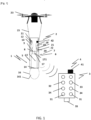
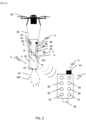
- the invention relates to a device 1 for generating a shock wave by detonation, this device 1 being coupleable to a carrier 23 of remotely piloted aircraft type, such as the drone shown in figure 1 , to form a flying machine as illustrated in figures 1 And 2 .
- the device 1 will be described below in the context of an application to a device 1 for triggering an avalanche but other applications of the shock wave generated, such as fire extinguishing or crop protection against hail, can also be envisaged without departing from the scope of the present invention.
- This device 1 therefore comprises an assembly 2, a remote control 3 and a system 4 for communication by wireless link between the remote control 3 and said assembly 2 for remote control of said assembly 2 with said remote control 3.
- the wireless communication system 4 which is a radio communication system, comprises a transmitter 41 integrated into the remote control 3 and a receiver 42 integrated into said assembly 2.
- the assembly 2 weighs less than 15 kg.
- the assembly 2 comprises a detonation tube 5.
- This detonation tube 5 may be made of a strong and lightweight material.
- this detonation tube 5 may be made of plastic for a single-use tube or of metal for a non-single-use tube.
- This detonation tube 5 is, in the example shown, a cylindrical tube.
- This detonation tube 5 is a rigid tube which may, for example, have a length of 1000 mm and a diameter of 200 mm.
- This detonation tube 5 internally delimits an enclosure 13 which has an outlet mouth 14 arranged, in the examples shown, at the level of one of the ends called the lower end of the detonation tube 5.
- the device 1 comprises a system 16 for sealing this outlet mouth 14.
- the closure system 16 is, independently of its embodiment, a pressure-sensitive closure system 16 configured to switch from a so-called closed state corresponding to the closed state of the outlet mouth 14 of the detonation tube 5 to a so-called open state corresponding to the open state of the outlet mouth 14 of the detonation tube 5 as a function of the pressure prevailing inside the detonation tube 5.
- the closure system 16 comprises an inflatable element 161 fixed to the detonation tube 5 and configured to detach at least partially from the detonation tube 5 in the inflated state beyond a predetermined inflation pressure.
- This closure system 16 could similarly have been produced in the form of a valve returned to the closed position or a film or a membrane or any closure system with equivalent operation.
- the enclosure 13 of the detonation tube 5 is intended to be filled with a fuel/detonating oxidant mixture capable of being ignited. It is understood that the explosion of the mixture causes an overpressure inside the detonation tube 5 capable of triggering the transition of the closure system 16 from the closed state to the open state.
- the device 1 comprises a first closable conduit 6 for supplying fluid to the detonation tube 5 connectable to a source of oxidant, such as oxygen, for example in the form of an oxygen cylinder, or compressed air supplied, for example, by a compressor.
- the first conduit 6 is, for its closure, equipped with a closure member 7, such as a solenoid valve or a manually actuated valve.
- the enclosure 13 of the detonation tube 5 can be a closed enclosure inside which the oxidant can be trapped.
- the detonation tube 5 can therefore be prefilled with oxidant before its transport.
- a flow meter or a pressure sensor of the enclosure can make it possible to control the filling of the detonation tube 5.
- the first conduit 6 can be closed and the source of oxidant can be removed from the device 1 because it is no longer necessary for the subsequent operation of the device 1 until the mixture is ignited.
- the device 1 also comprises a second closable conduit 8 for supplying fluid to the detonation tube 5 connectable to a source 10 of fuel that can be loaded onto said assembly 2, that is to say transportable with the detonation tube 5.
- This fuel source 10 can be formed by a tank containing a fuel in liquid form or in gaseous form such as hydrogen or propane.
- the device 1 may comprise a heating system, such as an electrical resistor, arranged around the tank to bring the fuel to a predetermined temperature before admission of the fuel into the detonation tube 5.
- a heating system such as an electrical resistor
- the second closable conduit 8 is equipped, for its closure, with a closure member such as a solenoid valve, shown at 9 in the figures.
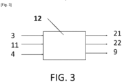
- This closure member is mounted to move between a closed position and an open position of the second conduit 8 and is capable of being controlled in movement by a control unit 12 of the device 1 which will be described below, this control unit 12 being capable of receiving as input data resulting from the actuation of the remote control.
- the fuel is introduced into the detonation tube 5 to form, with the oxidant already present in the tube, a fuel/detonating oxidant mixture.
- the fuel source 10 which is formed by a propane tank, is fixed at the upper end of the detonation tube 5 in the vertically positioned state of the detonation tube 5 with the lower end of the tube forming the outlet mouth 14 of the detonation tube 5 provided with the closure system 16.
- the detonation tube 5 is delimited by a peripheral side wall. This peripheral side wall can extend beyond the upper end of the detonation tube 5 to form an open housing inside which the fuel source 10 can be arranged. This fuel source 10 is thus protected during transport of the assembly 2.
- This fuel source 10 and the detonation tube 5 are thus integral during movement.
- the first conduit 6 passes through the peripheral side wall of the tube to open into the detonation tube 5.
- the first and second conduits are as short as possible to reduce the weight of the assembly 2.
- the assembly 2 further comprises an electrical energy storage unit 11, such as a battery.
- This electrical energy storage unit 11 may, similarly to the fuel source 10, be housed in a housing provided in the extension of the upper end of the detonation tube 5.
- This electrical energy storage unit 11 may be equipped with a sensor for detecting the electrical voltage of said unit 11.
- said assembly 2 also comprises a control unit 12.
- Said control unit 12 is in the form of an electronic and/or computer system which comprises for example a microprocessor and a working memory.
- the control unit may be in the form of a programmable automaton.
- the functions and steps described may be implemented in the form of a computer program or via hardware components (e.g. programmable gate arrays).
- the functions and steps operated by the control unit or its modules may be carried out by instruction sets or computer modules implemented in a processor or controller or be carried out by dedicated electronic components or FPGA or ASIC type components. It is also possible to combine computer parts and electronic parts. Where it is specified that the unit or means or modules of said unit are configured to perform a given operation, this means that the unit comprises computer instructions and the corresponding execution means which enable said operation to be performed and/or that the unit comprises corresponding electronic components.
- control unit 12 is configured at least to control the opening of the second conduit 8 by action on the member 9 for closing or closing the second conduit 8.
- the control unit 12 of said assembly 2 is configured to receive data from the electrical energy storage unit 11.
- the electrical voltage detection sensor can send a signal to the control unit 12.
- the control unit 12 is capable, depending on the signal, of detecting a failure of the electrical energy storage unit 11 and controlling the rest of said assembly 2 accordingly.
- the assembly 2 comprises attachment means 15.
- These attachment means 15 are configured to enable coupling of the assembly 2 to the carrier 23 formed by the drone in the example shown.
- These attachment means 15 can take a large number of forms.
- the attachment means 15 comprise cables fixed to one end of the axial extension of the detonation tube 5 and equipped at their opposite end with snap hooks to enable attachment by said cables in the suspended state of the assembly 2 to the carrier 23.
- the assembly 2 also comprises a main control 17 for opening the closing system 16.
- This main control 17 comprises a detonator 171 extending at least partially inside the detonation tube 5.
- This main control 17 can be controlled from the remote control 3 which will be described in more detail below.
- detonator 171 is meant here any system allowing initiation of the detonation of the fuel/oxidant mixture.
- This detonator can be an ignition device.
- This ignition device can be of the piezoelectric type. It can also comprise a flint or an electric explosive igniter or ignition electrodes associated with a high voltage source to create an arc between said electrodes.
- such a detonator 171 allows, in the activated state, ignition of the detonating fuel/oxidant mixture.
- This detonator 171 is active in the actuated state of the control member(s) of the main opening control 17 of the closing system 16, these control members 34, such as control buttons, being carried by the remote control 3.
- the assembly 2 comprises an auxiliary control 18 called an emergency control for opening the closing system 16.
- This emergency control 18 comprises a reserve 19 of pressurized gas capable of being carried by the detonation tube 5, i.e. capable of being mounted on the assembly 2 and a closable connection 20 for connecting the gas reserve 19 to the detonation tube 5.
- This closable connection 20 is equipped, for its closure, with one or more closure members. The or each closure member is mounted to move between an open position and a closed position. In the examples shown, two sealing members, which will be described below, are provided.
- the pressurized gas reserve 19 is a gas cartridge which can again be housed in the housing provided by the axial extension of the detonation tube 5. This gas reserve 19 is therefore here next to the fuel source 10.
- the gas in the pressurized gas reserve 19 of the emergency control 18 is a so-called neutral gas, i.e. not chemically reactive with the fuel/detonating oxidant gas mixture.
- this gas can be carbon dioxide or an inert gas such as argon or nitrogen.
- this gas reserve 19 allows, in the pre-filled state of the enclosure with oxidant, the passage of the system 16 for closing the outlet mouth of the detonation tube 5 from the closed state to the open state by simply opening the closable connection 20 for connecting the gas reserve to the detonation tube 5 of said emergency control 18.
- This opening of the closable connection 20 for connecting the gas reserve 19 to the detonation tube 5 of said emergency control 18 is only triggered when this is necessary to disarm the assembly 2. Indeed, the opening of the closable connection 20 for connecting the gas reserve 19 to the detonation tube 5 of the emergency control 18 makes it possible to increase the pressure inside the detonation tube 5. This increase in pressure causes the system 16 for sealing the outlet mouth 14 of the detonation tube 5 to change from the closed state to the open state. Once the outlet mouth 14 is open, all the oxidant pushed by the neutral gas from the gas reserve escapes from the detonation tube 5 so that any further use is impossible. The same phenomenon is observed even after introduction of fuel into the detonation tube 5 as long as the main control 17 has not been commanded into operation from the remote control 3.
- the assembly 2 comprises a main control 17 and an emergency control 18 for opening the sealed closure system 16, one capable of allowing the closure system 16 to be opened by detonation of the oxidant/fuel mixture, the other by admitting gas inside the tube. 5 detonation.
- These main and emergency controls 17 can be controlled in particular from the remote control 3.
- the remote control 3 comprises manually operable control members.
- These control members comprise at least one member 31 for controlling the on/off of the device 1, a member 33 for controlling the opening/closing of the second closable conduit 8, one or more members 34 for controlling the main control 17 for opening the closing system 16 and a member 35 for controlling the emergency control 18 for opening the closing system 16 active on the opening/closing of the closable connection 20 for connecting the gas reserve 19 to the detonation tube 5 of said emergency control 18.
- control members 34 of the main control 17 for opening the closing system 18 and several on/off control members 31 of the device 1 are provided.
- the presence of several control members to be actuated simultaneously constitutes a safety feature.
- untimely activation of the main control 17 or untimely starting of the remote control are prevented.
- the closable connection 20 for connecting the gas reserve 19 to the detonation tube 5 of the emergency control 18 may be equipped with one or more closure members.
- two closure members shown at 21 and 22 in the figures are arranged in series on said connection 20.
- Each closure member is formed by a solenoid valve.
- the control unit 12 is configured to control the transition from the closed state to the open state and vice versa of said closure members 21 and 22 depending on a certain number of conditions which will be described below.
- control unit 12 of said assembly 2 is configured to control the transition from the closed state to the open state of the or at least one of the shutter members of the closable connection 20 of the gas reserve 19 to the detonation tube 5 of the emergency control 18 at least as a function of the data provided by the receiver 42 of the communication system 4 by wireless connection, this unit 12 for controlling said assembly 2 being of course configured to acquire data from the receiver 42 of the wireless communication system 4. It is thus possible to control the emergency control 18 automatically from the data provided by the receiver 42 of the wireless control system 4.
- control unit 12 is configured to control the emergency control 18, that is to say to control the opening of the closable connection 20 of the gas reserve 19 to the detonation tube 5 of the emergency control 18.
- the control unit 12 of said assembly 2 is also configured to control the transition from the closed state to the open state of the or at least one of the shutter members of the closable connection 20 for connecting the gas reserve 19 to the detonation tube 5 of the emergency control 18 for the transition to the open state of said connection 20 at least as a function of the data provided by the electrical energy storage unit 11.
- a failure of the energy storage unit 11 makes it possible to disarm the assembly 2.
- control unit 12 is configured to control the transition from the closed state to the open state of the or at least one of the shutter members of the closable connection 20 for connecting the gas reserve 19 to the detonation tube 5 of the emergency control 18 for the transition to the open state of said connection 20 at least in the actuated state of the control member 35 of the emergency control 18 for opening the closing system 16.
- This control member 35 of the emergency control 18 for opening the closing system 16 can be considered as the equivalent of an emergency stop button.
- one of the shutter members of the closable connection 20 for connecting the gas reserve 19 to the detonation tube 5 of the emergency control 18 is a normally closed shutter member formed by a solenoid valve and shown at 21 in the figures, while the other of the shutter members of the closable connection 20 for connecting the gas reserve 19 to the detonation tube 5 of the emergency control 18 is a normally open member formed by a solenoid valve and shown at 22 in the figures.
- the remote control 3 further comprises a control member 32, such as a button for arming the device 1, which can be manually actuated.
- This arming control member 32 may be common to or separate from the on/off control member(s) 31 of the device 1.
- these on/off arming control members are distinct because the device 1 is capable of operating with different assemblies 2. In the case where the device 1 is capable of operating with a single assembly 2, these members are common.
- control unit 12 is configured to control the transition from the closed state to the open state of the normally closed shutter member 21 at least in the actuated state of the arming control member 32 or the on/off control member 31 of the device 1 when the latter are common, and the control unit is configured to control the transition from the open state to the closed state of the normally open shutter member 22 at least in the actuated state of the on/off control member 31 of the device 1.
- the control unit 12 is configured to control the transition from the open state to the closed state of the normally closed shutter member 21 and the transition from the closed state to the open state of the normally open shutter member 22 at least in the actuated state of the control member(s) 34 of the main opening control 17 of the closing system 16.
- the detonation tube 5 of the assembly 2 has been prefilled with oxidant to allow a predetermined pressure to be obtained inside the enclosure 13 of the detonation tube 5. It is assumed that the assembly 2 has been attached to the carrier 23 formed by a drone. The device thus formed is capable of flying. It is assumed that the remote control is started by simultaneously actuating the two on/off control members of said remote control. 3. At this stage, the normally open shutter member 22 of the closable connection 20 of the gas reserve 19 to the detonation tube 5 of the emergency control 18 is closed by the control unit 12 of said assembly 2.
- the operator can select if necessary, by actuating a control member of the remote control, the detonation tube 5 corresponding to the assembly 2 coupled to the carrier 23.
- the operator actuates the arming control member 32 of the remote control.
- the control unit 12 controls the transition from the closed state to the open state of the normally closed shutter member 21 of the closable connection 20 for connecting the gas reserve 19 to the detonation tube 5 of the emergency control 18.
- the detonation tube 5 is said to be armed.
- the carrier 23 is piloted to the desired target location for a detonation.
- the carrier 23 flies over the site with the outlet mouth 14 of the detonation tube 5 oriented towards the ground.
- the operator actuates, on the remote control 3, the opening/closing control member 33 of the second closable conduit 8 to supply the detonation tube 5 with fuel.
- the control unit 12 controls the opening of the second conduit 8 by actuating the closing member 9 of this second conduit 8.
- the operator then actuates on the remote control 3 the control members 34 of the main control 17 for opening the closing system 16.
- the control unit 12 is configured, from this actuation of the control members 34 of the main control 17 for opening the closing system 16, to control the operation of the detonator 171 which generates the ignition of the detonating mixture.
- the explosion of the detonating mixture generates the opening of the system 16 for closing the outlet mouth 14 of the detonation tube 5 and the shock wave propagates in the direction of the target.
- the mission of the device 1 is completed.
- control unit is configured to control the transition to the open state of the normally open shutter member and the transition to the closed state of the normally closed shutter member of the connection. 20 closable connection of the gas reserve to the tube of said emergency control.
- the device must return to the ground to allow a new loading of oxidant into the detonation tube 5 and the change of the fuel reserve for a new shot.
- control organs of the remote control must be actuated in a predetermined order, this predetermined order corresponds to that described above.
- the actuation of a control organ in advance of the predetermined order has no effect.
- the system 16 for closing the outlet mouth 14 of the detonation tube 5 can change from the closed state to the open state if the emergency control 18 is activated, that is to say if the closable connection 20 for connecting the gas reserve 19 to the detonation tube 5 of the emergency control 18 is open, which corresponds after arming the device 1 to the change from the closed state to the open state of the normally open closure member 22 which was closed during arming.
- This opening can be controlled in different ways and in particular manually or automatically.
- the operator can actuate the control member 35 of the emergency control 18 equipping the remote control 3.
- the opening can also be controlled automatically via the control unit 12 according to the data provided to the control unit 12 by the energy storage unit 11 or by the receiver 42 of the communication system 4 to control an opening of the closable connection 20 of the gas reserve 19 to the detonation tube 5 of the emergency control 18, in particular when an insufficient electrical voltage or an absence of reception signal at the receiver are detected.
- the opening of the closable connection 20 for connecting the gas reserve 19 to the detonation tube 5 results in a gas supply to the enclosure 13 of the detonation tube 5.
- This gas supply creates an overpressure in the enclosure 13 of the detonation tube 5 and consequently the passage of the system 16 for closing the outlet mouth of the detonation tube 5 from the closed state to the open state.
- the oxidant pushed by the neutral gas escapes into the atmosphere and a subsequent detonation is impossible. It should be noted that this opening can take place even at the stage where the enclosure 13 of the detonation tube 5 has been supplied with fuel. This results in perfectly safe operation of the device 1.
Landscapes
- Engineering & Computer Science (AREA)
- General Engineering & Computer Science (AREA)
- Filling Or Discharging Of Gas Storage Vessels (AREA)
Claims (15)
- Vorrichtung (1) zum Erzeugen einer Stoßwelle durch Detonation, wobei die Vorrichtung (1) eine Anordnung (2), eine Fernbedienung (3) und ein System (4) zur drahtlosen Kommunikation zwischen der Fernbedienung (3) und der Anordnung (2) für eine Fernsteuerung der Anordnung (2) mit der Fernbedienung (3) umfasst, wobei die Anordnung (2) ein Detonationsrohr (5), eine erste absperrbare Leitung (6) zum Zuführen von Fluid zum Detonationsrohr (5), die an eine Sauerstoffträgerquelle angeschlossen werden kann, eine zweite absperrbare Leitung (8) zum Zuführen von Fluid zum Detonationsrohr (5), die an eine Brennstoffquelle (10) angeschlossen werden kann, die an der Anordnung (2) angebracht werden kann, eine elektrische Energiespeichereinheit (11) und eine Steuereinheit (12) umfasst, wobei das Detonationsrohr (5) ein Gehäuse (13) begrenzt, das mindestens eine Auslassöffnung (14) aufweist, und
dass die Anordnung (2), die mit Befestigungsmitteln (15) ausgestattet ist, um ein Koppeln der Anordnung (2) mit einem Träger (23) vom Typ ferngesteuertes Flugzeug zu ermöglichen, ein System (16) zum dichten Verschließen der mindestens einen Auslassöffnung (14) des Detonationsrohrs (5) umfasst, um ein Vorfüllen des Gehäuses (13) mit dem Sauerstoffträger zu ermöglichen, dass das druckempfindliche Schließsystem (16) dazu konfiguriert ist, von einem geschlossenen Zustand, der dem geschlossenen Zustand der Auslassöffnung (14) des Detonationsrohrs (5) entspricht, in einen offenen Zustand, der dem offenen Zustand der Austrittsmündung (14) des Detonationsrohrs (5) entspricht, in Abhängigkeit vom im Inneren des Detonationsrohrs (5) herrschenden Druck überzugehen, dass die Steuereinheit (12) dazu konfiguriert ist, mindestens das Öffnen der zweiten Leitung (8) zu steuern, um das Bilden eines explosiven gasförmigen Gemischs aus Sauerstoffträger und Brennstoff im Inneren des Detonationsrohrs (5) im vorgefüllten Zustand des Detonationsrohrs (5) mit dem Sauerstoffträger zu ermöglichen, und dass die Anordnung (2) eine Hauptöffnungssteuerung (17) für das Schließsystem (16) und eine Hilfsöffnungssteuerung (18), Notöffnungssteuerung genannt, für das Schließsystem (16) umfasst, wobei die Notsteuerung (18) einen Druckgasvorrat (19), der dazu ausgelegt ist, durch das Detonationsrohr (5) transportiert zu werden, und eine absperrbare Verbindung (20) für das Anschließen des Gasvorrats (19) an das Detonationsrohr (5) umfasst, die mit einem oder mehreren Absperrelementen (21, 22) ausgestattet ist, wobei das oder jedes Absperrelement (21, 22) zwischen einer offenen Position und einer geschlossenen Position beweglich montiert ist. - Vorrichtung (1) zum Erzeugen einer Stoßwelle durch Detonation nach Anspruch 1, dadurch gekennzeichnet, dass die Fernbedienung (3) manuell betätigbare Steuerelemente umfasst, wobei die Steuerelemente mindestens ein Steuerelement (31) zum Ein-/Ausschalten der Vorrichtung (1), ein Steuerelement (33) zum Öffnen/Schließen der zweiten absperrbaren Leitung (8), ein oder mehrere Steuerelemente (34) für die Hauptöffnungssteuerung (17) für das Schließsystem (16) und ein Steuerelement (35) für die Notöffnungssteuerung (18) für das Schließsystem (16), das beim Öffnen/Schließen der absperrbaren Verbindung (20) zum Anschließen des Gasvorrats (19) an das Detonationsrohr (5) der Notsteuerung (18) aktiv ist, umfassen.
- Vorrichtung (1) zum Erzeugen einer Stoßwelle durch Detonation nach einem der Ansprüche 1 oder 2, dadurch gekennzeichnet, dass das drahtlose Kommunikationssystem (4) mindestens einen in die Fernbedienung (3) integrierten Sender (41) und mindestens einen in die Anordnung (2) integrierten Empfänger (42) umfasst und dass die Steuereinheit (12) der Anordnung (2) dazu konfiguriert ist, Daten vom Empfänger (42) des drahtlosen Kommunikationssystems (4) zu erfassen.
- Vorrichtung (1) zum Erzeugen einer Stoßwelle durch Detonation nach einem der Ansprüche 1 bis 3, dadurch gekennzeichnet, dass die Steuereinheit (12) der Anordnung (2) dazu konfiguriert ist, Daten von der elektrischen Energiespeichereinheit (11) zu erfassen.
- Vorrichtung (1) zum Erzeugen einer Stoßwelle durch Detonation nach einem der Ansprüche 1 bis 4, dadurch gekennzeichnet, dass die absperrbare Verbindung (20) zum Anschließen des Gasvorrats (19) an das Detonationsrohr (5) der Notsteuerung (18) mit mehreren Absperrelementen (21, 22) ausgestattet ist, wobei die Absperrelemente (21, 22) in Reihe an der Verbindung (20) angeordnet sind.
- Vorrichtung (1) zum Erzeugen einer Stoßwelle durch Detonation nach einem der Ansprüche 1 bis 5 in Kombination mit Anspruch 3, dadurch gekennzeichnet, dass die Steuereinheit (12) der Anordnung (2) dazu konfiguriert ist, den Übergang vom geschlossenen Zustand in den offenen Zustand des oder des mindestens einen der Absperrelemente (21, 22) für die absperrbare Verbindung (20) zum Anschließen des Gasvorrats (19) an das Detonationsrohr (5) der Notsteuerung (18) mindestens in Abhängigkeit von den vom Empfänger (42) des drahtlosen Kommunikationssystems (4) gelieferten Daten zu steuern.
- Vorrichtung (1) zum Erzeugen einer Stoßwelle durch Detonation nach einem der Ansprüche 1 bis 6 in Kombination mit Anspruch 4, dadurch gekennzeichnet, dass die Steuereinheit (12) der Anordnung (2) dazu konfiguriert ist, den Übergang vom geschlossenen Zustand in den offenen Zustand des oder des mindestens einen der Absperrelemente (21, 22) für die absperrbare Verbindung (20) zum Anschließen des Gasvorrats (19) an das Detonationsrohr (5) der Notsteuerung (18) mindestens in Abhängigkeit von den von der elektrischen Energiespeichereinheit (11) gelieferten Daten zu steuern.
- Vorrichtung (1) zum Erzeugen einer Stoßwelle durch Detonation nach einem der Ansprüche 1 bis 7 in Verbindung mit Anspruch 2, dadurch gekennzeichnet, dass die Steuereinheit (12) dazu konfiguriert ist, den Übergang vom geschlossenen Zustand in den offenen Zustand des oder des mindestens einen der Absperrelemente (21, 22) für die absperrbare Verbindung (20) zum Anschließen des Gasvorrats (19) an das Detonationsrohr (5) der Notsteuerung (18) mindestens im betätigten Zustand des Steuerelements (35) der Notöffnungssteuerung (18) für das Schließsystem (16) zu steuern.
- Vorrichtung (1) zum Erzeugen einer Stoßwelle durch Detonation nach einem der Ansprüche 1 bis 8 in Verbindung mit Anspruch 2, dadurch gekennzeichnet, dass die Fernbedienung (3) mindestens ein Steuerelement (32) zum Laden der manuell betätigbaren Vorrichtung (1) umfasst, wobei das Steuerelement (32) gemeinsam oder getrennt von dem oder den Steuerelementen (31) für das Ein-/Ausschalten der Vorrichtung (1) ist, dass mindestens eines (21) der Absperrelemente (21, 22) für die absperrbare Verbindung (20) zum Anschließen des Gasvorrats (19) an das Detonationsrohr (5) der Notsteuerung (18) ein normalerweise geschlossenes Absperrelement ist und dass die Steuereinheit (12) dazu konfiguriert ist, den Übergang vom geschlossenen Zustand in den offenen Zustand des normalerweise geschlossenen Absperrelements mindestens im betätigten Zustand des Ladesteuerelements (32) zu steuern.
- Vorrichtung (1) zum Erzeugen einer Stoßwelle durch Detonation nach einem der Ansprüche 1 bis 9 in Kombination mit Anspruch 2, dadurch gekennzeichnet, dass die Fernbedienung (3) mindestens ein Steuerelement (32) zum Laden der manuell betätigbaren Vorrichtung (1) umfasst, wobei das Steuerelement (32) gemeinsam oder getrennt von dem oder den Steuerelementen (31) für das Ein-/Ausschalten der Vorrichtung (1) ist, dass mindestens eines (22) der Absperrelemente (21, 22) für die absperrbare Verbindung (20) zum Anschließen des Gasvorrats (19) an das Detonationsrohr (5) der Notsteuerung (18) ein normalerweise offenes Absperrelement ist und dass die Steuereinheit (12) dazu konfiguriert ist, den Übergang vom offenen Zustand in den geschlossenen Zustand des normalerweise offenen Absperrelements mindestens im betätigten Zustand des Ladesteuerelements (32) für das Ein-/Ausschalten der Vorrichtung (1) zu steuern.
- Vorrichtung (1) zum Erzeugen einer Stoßwelle durch Detonation nach Anspruch 10 in Kombination mit Anspruch 9, dadurch gekennzeichnet, dass die Steuereinheit (12) dazu konfiguriert ist, den Übergang vom offenen Zustand in den geschlossenen Zustand des normalerweise geschlossenen Absperrelements (21) und den Übergang vom geschlossenen Zustand in den offenen Zustand des normalerweise offenen Absperrelements mindestens im betätigten Zustand des oder der Steuerelemente (34) der Hauptöffnungssteuerung (17) des Schließsystems (16) zu steuern.
- Vorrichtung (1) zum Erzeugen einer Stoßwelle durch Detonation nach einem der Ansprüche 1 bis 11, dadurch gekennzeichnet, dass das Gas aus dem Druckgasvorrat (19) der Notsteuerung (18) ein neutrales Gas, d. h. ein nicht chemisch mit dem explosiven gasförmigen Gemisch aus Sauerstoffträger und Brennstoff reaktives, ist.
- Vorrichtung (1) zum Erzeugen einer Stoßwelle durch Detonation nach einem der Ansprüche 1 bis 12, dadurch gekennzeichnet, dass die Hauptöffnungssteuerung (17) des Schließsystems (16) einen Detonator (171) umfasst, der sich mindestens teilweise in das Innere des Detonationsrohrs (5) erstreckt.
- Vorrichtung (1) zum Erzeugen einer Stoßwelle durch Detonation nach einem der Ansprüche 1 bis 13, dadurch gekennzeichnet, dass das Schließsystem (16) ein aufblasbares Element (161) umfasst, das an dem Detonationsrohr (5) befestigt und dazu konfiguriert ist, sich im aufgeblasenen Zustand ab einem vorbestimmten Aufblasdruck mindestens teilweise vom Detonationsrohr (5) zu lösen.
- Flugkörper, der einen Träger (23) vom Typ ferngesteuertes Flugzeug und eine Vorrichtung (1) zum Erzeugen einer Stoßwelle durch Detonation umfasst, dadurch gekennzeichnet, dass die Vorrichtung (1) zum Erzeugen einer Stoßwelle durch Detonation einem der Ansprüche 1 bis 14 entspricht und dass die Anordnung (2) der Vorrichtung (1) an den Träger (23) gekoppelt werden kann.
Priority Applications (1)
| Application Number | Priority Date | Filing Date | Title |
|---|---|---|---|
| SI202130238T SI4263348T1 (sl) | 2020-12-15 | 2021-12-13 | Naprava za generiranje udarnega vala |
Applications Claiming Priority (2)
| Application Number | Priority Date | Filing Date | Title |
|---|---|---|---|
| FR2013243A FR3117581B1 (fr) | 2020-12-15 | 2020-12-15 | Dispositif pour générer une onde de choc |
| PCT/FR2021/052290 WO2022129754A1 (fr) | 2020-12-15 | 2021-12-13 | Dispositif pour générer une onde de choc |
Publications (2)
| Publication Number | Publication Date |
|---|---|
| EP4263348A1 EP4263348A1 (de) | 2023-10-25 |
| EP4263348B1 true EP4263348B1 (de) | 2024-09-04 |
Family
ID=74860091
Family Applications (1)
| Application Number | Title | Priority Date | Filing Date |
|---|---|---|---|
| EP21848003.6A Active EP4263348B1 (de) | 2020-12-15 | 2021-12-13 | Vorrichtung zur erzeugung einer stosswelle |
Country Status (5)
| Country | Link |
|---|---|
| EP (1) | EP4263348B1 (de) |
| ES (1) | ES2998332T3 (de) |
| FR (1) | FR3117581B1 (de) |
| SI (1) | SI4263348T1 (de) |
| WO (1) | WO2022129754A1 (de) |
Family Cites Families (4)
| Publication number | Priority date | Publication date | Assignee | Title |
|---|---|---|---|---|
| FR2897931B1 (fr) * | 2006-02-24 | 2008-05-09 | Technologie Alpine De Securite | Dispositif de declenchement d'avalanche |
| FR2925152B1 (fr) * | 2007-12-14 | 2013-06-28 | Technologie Alpine De Securite T A S | Dispositif de declenchement d'avalanches |
| FR2958739B1 (fr) * | 2010-04-09 | 2012-05-11 | Technologie Alpine De Securite Tas | Dispositif de declenchement d'avalanche |
| WO2018182944A1 (en) * | 2017-03-25 | 2018-10-04 | Yu Simon Siu Chi | Multi-function photo electro acoustic ions drone |
-
2020
- 2020-12-15 FR FR2013243A patent/FR3117581B1/fr active Active
-
2021
- 2021-12-13 EP EP21848003.6A patent/EP4263348B1/de active Active
- 2021-12-13 WO PCT/FR2021/052290 patent/WO2022129754A1/fr not_active Ceased
- 2021-12-13 SI SI202130238T patent/SI4263348T1/sl unknown
- 2021-12-13 ES ES21848003T patent/ES2998332T3/es active Active
Also Published As
| Publication number | Publication date |
|---|---|
| FR3117581A1 (fr) | 2022-06-17 |
| ES2998332T3 (en) | 2025-02-19 |
| FR3117581B1 (fr) | 2022-11-25 |
| SI4263348T1 (sl) | 2025-03-31 |
| WO2022129754A1 (fr) | 2022-06-23 |
| EP4263348A1 (de) | 2023-10-25 |
Similar Documents
| Publication | Publication Date | Title |
|---|---|---|
| CA2707034C (fr) | Dispositif de declenchement d'avalanches | |
| EP2556330B1 (de) | Vorrichtung zur auslösung einer lawine | |
| EP1987290A1 (de) | Lawinenauslösesystem | |
| EP4255808A1 (de) | Flugzeugtürarchitektur mit einer notenergiequelle | |
| EP0018883B1 (de) | Verfahren zur Verringerung der Entzündungs- und Explosionsgefahr infolge des Zerfalls von Hochdruckäthylen und Vorrichtung zur Durchführung des Verfahrens | |
| FR2564965A1 (fr) | Dispositif d'interruption de chaine pyrotechnique sensible a la temperature | |
| EP4263348B1 (de) | Vorrichtung zur erzeugung einer stosswelle | |
| EP3141695A1 (de) | System und verfahren zur frakturierung eines festmaterials | |
| WO2012035215A1 (fr) | Projectile pour déclenchement d'avalanche | |
| EP2275774A1 (de) | Munition mit Mitteln zur Neutralisierung seiner Sprengladung | |
| BE1010421A3 (fr) | Dispositif de mise sous pression d'appareil de lutte contre l'incendie a cartouches pyrotechniques rechargeables generatrices de gaz et extincteur muni d'un tel dispositif. | |
| FR2528107A1 (fr) | Procede et dispositif pour extraire des materiaux dans des espaces incontrolables de mines par tirage d'une charge importante, avec protection contre les explosions de grisou | |
| EP4042097B1 (de) | Lawinenauslösesystem | |
| EP1902757A1 (de) | Antriebsvorrichtung für ein in einem Hohlraum enthaltenem Mittel | |
| FR2483068A1 (fr) | Fusee electronique pour grenade a main ou a fusil | |
| EP0232194A1 (de) | Pyrotechnische Vorrichtung zum Wegräumen von Minen oder zum Erzeugen von Brand | |
| EP0758438B1 (de) | Vorrichtung zum koordinierten steuern von mindestens zwei gasströmen, und damit ausgerüstete brenner | |
| FR2988389A1 (fr) | Composition deflagrante pour le declanchement d'avalanche et procede de declenchement d'avalanche | |
| FR2652644A2 (en) | Device for unconfining a military charge containing an explosive | |
| FR3073499A1 (fr) | Ejecteur de parachute de secours pour parapente ou aeronef ultraleger | |
| EP1008830B1 (de) | Unterwasserschutzladung | |
| WO1990001446A1 (fr) | Systeme de largage de charges lourdes a partir d'aeronefs | |
| EP1923659B1 (de) | Schutzsystem für eine Vorrichtung, die eine Substanz enthält, die heftig auf Erhitzung reagiert | |
| FR2907732A1 (fr) | Generateur de gaz hybride de gonflage d'un coussin de securite pour vehicule automobile | |
| EP0486334B1 (de) | Vorrichtung zur Kühlung eines Raumes mit einem Einspritzventil |
Legal Events
| Date | Code | Title | Description |
|---|---|---|---|
| STAA | Information on the status of an ep patent application or granted ep patent |
Free format text: STATUS: UNKNOWN |
|
| STAA | Information on the status of an ep patent application or granted ep patent |
Free format text: STATUS: THE INTERNATIONAL PUBLICATION HAS BEEN MADE |
|
| PUAI | Public reference made under article 153(3) epc to a published international application that has entered the european phase |
Free format text: ORIGINAL CODE: 0009012 |
|
| STAA | Information on the status of an ep patent application or granted ep patent |
Free format text: STATUS: REQUEST FOR EXAMINATION WAS MADE |
|
| 17P | Request for examination filed |
Effective date: 20230704 |
|
| AK | Designated contracting states |
Kind code of ref document: A1 Designated state(s): AL AT BE BG CH CY CZ DE DK EE ES FI FR GB GR HR HU IE IS IT LI LT LU LV MC MK MT NL NO PL PT RO RS SE SI SK SM TR |
|
| P01 | Opt-out of the competence of the unified patent court (upc) registered |
Effective date: 20231103 |
|
| DAV | Request for validation of the european patent (deleted) | ||
| DAX | Request for extension of the european patent (deleted) | ||
| GRAP | Despatch of communication of intention to grant a patent |
Free format text: ORIGINAL CODE: EPIDOSNIGR1 |
|
| STAA | Information on the status of an ep patent application or granted ep patent |
Free format text: STATUS: GRANT OF PATENT IS INTENDED |
|
| INTG | Intention to grant announced |
Effective date: 20240426 |
|
| GRAS | Grant fee paid |
Free format text: ORIGINAL CODE: EPIDOSNIGR3 |
|
| GRAA | (expected) grant |
Free format text: ORIGINAL CODE: 0009210 |
|
| STAA | Information on the status of an ep patent application or granted ep patent |
Free format text: STATUS: THE PATENT HAS BEEN GRANTED |
|
| AK | Designated contracting states |
Kind code of ref document: B1 Designated state(s): AL AT BE BG CH CY CZ DE DK EE ES FI FR GB GR HR HU IE IS IT LI LT LU LV MC MK MT NL NO PL PT RO RS SE SI SK SM TR |
|
| REG | Reference to a national code |
Ref country code: GB Ref legal event code: FG4D Free format text: NOT ENGLISH |
|
| REG | Reference to a national code |
Ref country code: CH Ref legal event code: EP |
|
| REG | Reference to a national code |
Ref country code: IE Ref legal event code: FG4D Free format text: LANGUAGE OF EP DOCUMENT: FRENCH |
|
| REG | Reference to a national code |
Ref country code: DE Ref legal event code: R096 Ref document number: 602021018480 Country of ref document: DE |
|
| REG | Reference to a national code |
Ref country code: LT Ref legal event code: MG9D |
|
| REG | Reference to a national code |
Ref country code: SE Ref legal event code: TRGR |
|
| REG | Reference to a national code |
Ref country code: NL Ref legal event code: MP Effective date: 20240904 |
|
| PG25 | Lapsed in a contracting state [announced via postgrant information from national office to epo] |
Ref country code: PL Free format text: LAPSE BECAUSE OF FAILURE TO SUBMIT A TRANSLATION OF THE DESCRIPTION OR TO PAY THE FEE WITHIN THE PRESCRIBED TIME-LIMIT Effective date: 20240904 Ref country code: GR Free format text: LAPSE BECAUSE OF FAILURE TO SUBMIT A TRANSLATION OF THE DESCRIPTION OR TO PAY THE FEE WITHIN THE PRESCRIBED TIME-LIMIT Effective date: 20241205 Ref country code: FI Free format text: LAPSE BECAUSE OF FAILURE TO SUBMIT A TRANSLATION OF THE DESCRIPTION OR TO PAY THE FEE WITHIN THE PRESCRIBED TIME-LIMIT Effective date: 20240904 |
|
| PG25 | Lapsed in a contracting state [announced via postgrant information from national office to epo] |
Ref country code: BG Free format text: LAPSE BECAUSE OF FAILURE TO SUBMIT A TRANSLATION OF THE DESCRIPTION OR TO PAY THE FEE WITHIN THE PRESCRIBED TIME-LIMIT Effective date: 20240904 |
|
| PG25 | Lapsed in a contracting state [announced via postgrant information from national office to epo] |
Ref country code: LV Free format text: LAPSE BECAUSE OF FAILURE TO SUBMIT A TRANSLATION OF THE DESCRIPTION OR TO PAY THE FEE WITHIN THE PRESCRIBED TIME-LIMIT Effective date: 20240904 |
|
| PG25 | Lapsed in a contracting state [announced via postgrant information from national office to epo] |
Ref country code: HR Free format text: LAPSE BECAUSE OF FAILURE TO SUBMIT A TRANSLATION OF THE DESCRIPTION OR TO PAY THE FEE WITHIN THE PRESCRIBED TIME-LIMIT Effective date: 20240904 |
|
| PG25 | Lapsed in a contracting state [announced via postgrant information from national office to epo] |
Ref country code: RS Free format text: LAPSE BECAUSE OF FAILURE TO SUBMIT A TRANSLATION OF THE DESCRIPTION OR TO PAY THE FEE WITHIN THE PRESCRIBED TIME-LIMIT Effective date: 20241204 |
|
| PG25 | Lapsed in a contracting state [announced via postgrant information from national office to epo] |
Ref country code: RS Free format text: LAPSE BECAUSE OF FAILURE TO SUBMIT A TRANSLATION OF THE DESCRIPTION OR TO PAY THE FEE WITHIN THE PRESCRIBED TIME-LIMIT Effective date: 20241204 Ref country code: PL Free format text: LAPSE BECAUSE OF FAILURE TO SUBMIT A TRANSLATION OF THE DESCRIPTION OR TO PAY THE FEE WITHIN THE PRESCRIBED TIME-LIMIT Effective date: 20240904 Ref country code: LV Free format text: LAPSE BECAUSE OF FAILURE TO SUBMIT A TRANSLATION OF THE DESCRIPTION OR TO PAY THE FEE WITHIN THE PRESCRIBED TIME-LIMIT Effective date: 20240904 Ref country code: HR Free format text: LAPSE BECAUSE OF FAILURE TO SUBMIT A TRANSLATION OF THE DESCRIPTION OR TO PAY THE FEE WITHIN THE PRESCRIBED TIME-LIMIT Effective date: 20240904 Ref country code: GR Free format text: LAPSE BECAUSE OF FAILURE TO SUBMIT A TRANSLATION OF THE DESCRIPTION OR TO PAY THE FEE WITHIN THE PRESCRIBED TIME-LIMIT Effective date: 20241205 Ref country code: FI Free format text: LAPSE BECAUSE OF FAILURE TO SUBMIT A TRANSLATION OF THE DESCRIPTION OR TO PAY THE FEE WITHIN THE PRESCRIBED TIME-LIMIT Effective date: 20240904 Ref country code: BG Free format text: LAPSE BECAUSE OF FAILURE TO SUBMIT A TRANSLATION OF THE DESCRIPTION OR TO PAY THE FEE WITHIN THE PRESCRIBED TIME-LIMIT Effective date: 20240904 |
|
| PG25 | Lapsed in a contracting state [announced via postgrant information from national office to epo] |
Ref country code: NL Free format text: LAPSE BECAUSE OF FAILURE TO SUBMIT A TRANSLATION OF THE DESCRIPTION OR TO PAY THE FEE WITHIN THE PRESCRIBED TIME-LIMIT Effective date: 20240904 |
|
| REG | Reference to a national code |
Ref country code: ES Ref legal event code: FG2A Ref document number: 2998332 Country of ref document: ES Kind code of ref document: T3 Effective date: 20250219 |
|
| PG25 | Lapsed in a contracting state [announced via postgrant information from national office to epo] |
Ref country code: IS Free format text: LAPSE BECAUSE OF FAILURE TO SUBMIT A TRANSLATION OF THE DESCRIPTION OR TO PAY THE FEE WITHIN THE PRESCRIBED TIME-LIMIT Effective date: 20250104 Ref country code: PT Free format text: LAPSE BECAUSE OF FAILURE TO SUBMIT A TRANSLATION OF THE DESCRIPTION OR TO PAY THE FEE WITHIN THE PRESCRIBED TIME-LIMIT Effective date: 20250106 |
|
| PG25 | Lapsed in a contracting state [announced via postgrant information from national office to epo] |
Ref country code: SM Free format text: LAPSE BECAUSE OF FAILURE TO SUBMIT A TRANSLATION OF THE DESCRIPTION OR TO PAY THE FEE WITHIN THE PRESCRIBED TIME-LIMIT Effective date: 20240904 Ref country code: RO Free format text: LAPSE BECAUSE OF FAILURE TO SUBMIT A TRANSLATION OF THE DESCRIPTION OR TO PAY THE FEE WITHIN THE PRESCRIBED TIME-LIMIT Effective date: 20240904 |
|
| PG25 | Lapsed in a contracting state [announced via postgrant information from national office to epo] |
Ref country code: EE Free format text: LAPSE BECAUSE OF FAILURE TO SUBMIT A TRANSLATION OF THE DESCRIPTION OR TO PAY THE FEE WITHIN THE PRESCRIBED TIME-LIMIT Effective date: 20240904 |
|
| PG25 | Lapsed in a contracting state [announced via postgrant information from national office to epo] |
Ref country code: CZ Free format text: LAPSE BECAUSE OF FAILURE TO SUBMIT A TRANSLATION OF THE DESCRIPTION OR TO PAY THE FEE WITHIN THE PRESCRIBED TIME-LIMIT Effective date: 20240904 |
|
| PG25 | Lapsed in a contracting state [announced via postgrant information from national office to epo] |
Ref country code: SK Free format text: LAPSE BECAUSE OF FAILURE TO SUBMIT A TRANSLATION OF THE DESCRIPTION OR TO PAY THE FEE WITHIN THE PRESCRIBED TIME-LIMIT Effective date: 20240904 |
|
| PGFP | Annual fee paid to national office [announced via postgrant information from national office to epo] |
Ref country code: IT Payment date: 20241231 Year of fee payment: 4 |
|
| REG | Reference to a national code |
Ref country code: DE Ref legal event code: R097 Ref document number: 602021018480 Country of ref document: DE |
|
| PG25 | Lapsed in a contracting state [announced via postgrant information from national office to epo] |
Ref country code: MC Free format text: LAPSE BECAUSE OF FAILURE TO SUBMIT A TRANSLATION OF THE DESCRIPTION OR TO PAY THE FEE WITHIN THE PRESCRIBED TIME-LIMIT Effective date: 20240904 |
|
| PGFP | Annual fee paid to national office [announced via postgrant information from national office to epo] |
Ref country code: DE Payment date: 20250620 Year of fee payment: 4 |
|
| PG25 | Lapsed in a contracting state [announced via postgrant information from national office to epo] |
Ref country code: DK Free format text: LAPSE BECAUSE OF FAILURE TO SUBMIT A TRANSLATION OF THE DESCRIPTION OR TO PAY THE FEE WITHIN THE PRESCRIBED TIME-LIMIT Effective date: 20240904 |
|
| PGFP | Annual fee paid to national office [announced via postgrant information from national office to epo] |
Ref country code: ES Payment date: 20250624 Year of fee payment: 4 |
|
| PLBE | No opposition filed within time limit |
Free format text: ORIGINAL CODE: 0009261 |
|
| STAA | Information on the status of an ep patent application or granted ep patent |
Free format text: STATUS: NO OPPOSITION FILED WITHIN TIME LIMIT |
|
| PGFP | Annual fee paid to national office [announced via postgrant information from national office to epo] |
Ref country code: NO Payment date: 20250619 Year of fee payment: 4 |
|
| PGFP | Annual fee paid to national office [announced via postgrant information from national office to epo] |
Ref country code: FR Payment date: 20250618 Year of fee payment: 4 |
|
| PGFP | Annual fee paid to national office [announced via postgrant information from national office to epo] |
Ref country code: CH Payment date: 20250620 Year of fee payment: 4 |
|
| PGFP | Annual fee paid to national office [announced via postgrant information from national office to epo] |
Ref country code: TR Payment date: 20250610 Year of fee payment: 4 |
|
| PGFP | Annual fee paid to national office [announced via postgrant information from national office to epo] |
Ref country code: SE Payment date: 20250619 Year of fee payment: 4 Ref country code: SI Payment date: 20250606 Year of fee payment: 4 |
|
| 26N | No opposition filed |
Effective date: 20250605 |
|
| PG25 | Lapsed in a contracting state [announced via postgrant information from national office to epo] |
Ref country code: LU Free format text: LAPSE BECAUSE OF NON-PAYMENT OF DUE FEES Effective date: 20241213 |
|
| REG | Reference to a national code |
Ref country code: BE Ref legal event code: MM Effective date: 20241231 |
|
| REG | Reference to a national code |
Ref country code: AT Ref legal event code: UEP Ref document number: 1720144 Country of ref document: AT Kind code of ref document: T Effective date: 20240904 |
|
| PG25 | Lapsed in a contracting state [announced via postgrant information from national office to epo] |
Ref country code: BE Free format text: LAPSE BECAUSE OF NON-PAYMENT OF DUE FEES Effective date: 20241231 |
|
| PG25 | Lapsed in a contracting state [announced via postgrant information from national office to epo] |
Ref country code: IE Free format text: LAPSE BECAUSE OF NON-PAYMENT OF DUE FEES Effective date: 20241213 |
|
| PGFP | Annual fee paid to national office [announced via postgrant information from national office to epo] |
Ref country code: AT Payment date: 20260113 Year of fee payment: 5 |
|
| REG | Reference to a national code |
Ref country code: CH Ref legal event code: U11 Free format text: ST27 STATUS EVENT CODE: U-0-0-U10-U11 (AS PROVIDED BY THE NATIONAL OFFICE) Effective date: 20260429 |