EP4263407B1 - Support d'enrouleur de câble pour supporter en rotation un enrouleur de câble - Google Patents
Support d'enrouleur de câble pour supporter en rotation un enrouleur de câble Download PDFInfo
- Publication number
- EP4263407B1 EP4263407B1 EP21843594.9A EP21843594A EP4263407B1 EP 4263407 B1 EP4263407 B1 EP 4263407B1 EP 21843594 A EP21843594 A EP 21843594A EP 4263407 B1 EP4263407 B1 EP 4263407B1
- Authority
- EP
- European Patent Office
- Prior art keywords
- cable drum
- hydraulic
- actuator
- holding arms
- drum support
- Prior art date
- Legal status (The legal status is an assumption and is not a legal conclusion. Google has not performed a legal analysis and makes no representation as to the accuracy of the status listed.)
- Active
Links
Images


Classifications
-
- B—PERFORMING OPERATIONS; TRANSPORTING
- B65—CONVEYING; PACKING; STORING; HANDLING THIN OR FILAMENTARY MATERIAL
- B65H—HANDLING THIN OR FILAMENTARY MATERIAL, e.g. SHEETS, WEBS, CABLES
- B65H49/00—Unwinding or paying-out filamentary material; Supporting, storing or transporting packages from which filamentary material is to be withdrawn or paid-out
- B65H49/18—Methods or apparatus in which packages rotate
- B65H49/20—Package-supporting devices
- B65H49/32—Stands or frameworks
- B65H49/324—Constructional details
- B65H49/327—Arrangements or adaptations for attachment to a wall, a post or the like
-
- B—PERFORMING OPERATIONS; TRANSPORTING
- B65—CONVEYING; PACKING; STORING; HANDLING THIN OR FILAMENTARY MATERIAL
- B65H—HANDLING THIN OR FILAMENTARY MATERIAL, e.g. SHEETS, WEBS, CABLES
- B65H49/00—Unwinding or paying-out filamentary material; Supporting, storing or transporting packages from which filamentary material is to be withdrawn or paid-out
- B65H49/18—Methods or apparatus in which packages rotate
- B65H49/20—Package-supporting devices
- B65H49/30—Swifts or skein holders
- B65H49/305—Swifts or skein holders with axially adjustable or removable elements for retaining the package
-
- B—PERFORMING OPERATIONS; TRANSPORTING
- B65—CONVEYING; PACKING; STORING; HANDLING THIN OR FILAMENTARY MATERIAL
- B65H—HANDLING THIN OR FILAMENTARY MATERIAL, e.g. SHEETS, WEBS, CABLES
- B65H49/00—Unwinding or paying-out filamentary material; Supporting, storing or transporting packages from which filamentary material is to be withdrawn or paid-out
- B65H49/18—Methods or apparatus in which packages rotate
- B65H49/20—Package-supporting devices
- B65H49/32—Stands or frameworks
-
- B—PERFORMING OPERATIONS; TRANSPORTING
- B65—CONVEYING; PACKING; STORING; HANDLING THIN OR FILAMENTARY MATERIAL
- B65H—HANDLING THIN OR FILAMENTARY MATERIAL, e.g. SHEETS, WEBS, CABLES
- B65H75/00—Storing webs, tapes, or filamentary material, e.g. on reels
- B65H75/02—Cores, formers, supports, or holders for coiled, wound, or folded material, e.g. reels, spindles, bobbins, cop tubes, cans, mandrels or chucks
- B65H75/34—Cores, formers, supports, or holders for coiled, wound, or folded material, e.g. reels, spindles, bobbins, cop tubes, cans, mandrels or chucks specially adapted or mounted for storing and repeatedly paying-out and re-storing lengths of material provided for particular purposes, e.g. anchored hoses, power cables
- B65H75/38—Cores, formers, supports, or holders for coiled, wound, or folded material, e.g. reels, spindles, bobbins, cop tubes, cans, mandrels or chucks specially adapted or mounted for storing and repeatedly paying-out and re-storing lengths of material provided for particular purposes, e.g. anchored hoses, power cables involving the use of a core or former internal to, and supporting, a stored package of material
- B65H75/40—Cores, formers, supports, or holders for coiled, wound, or folded material, e.g. reels, spindles, bobbins, cop tubes, cans, mandrels or chucks specially adapted or mounted for storing and repeatedly paying-out and re-storing lengths of material provided for particular purposes, e.g. anchored hoses, power cables involving the use of a core or former internal to, and supporting, a stored package of material mobile or transportable
- B65H75/42—Cores, formers, supports, or holders for coiled, wound, or folded material, e.g. reels, spindles, bobbins, cop tubes, cans, mandrels or chucks specially adapted or mounted for storing and repeatedly paying-out and re-storing lengths of material provided for particular purposes, e.g. anchored hoses, power cables involving the use of a core or former internal to, and supporting, a stored package of material mobile or transportable attached to, or forming part of, mobile tools, machines or vehicles
-
- B—PERFORMING OPERATIONS; TRANSPORTING
- B65—CONVEYING; PACKING; STORING; HANDLING THIN OR FILAMENTARY MATERIAL
- B65H—HANDLING THIN OR FILAMENTARY MATERIAL, e.g. SHEETS, WEBS, CABLES
- B65H75/00—Storing webs, tapes, or filamentary material, e.g. on reels
- B65H75/02—Cores, formers, supports, or holders for coiled, wound, or folded material, e.g. reels, spindles, bobbins, cop tubes, cans, mandrels or chucks
- B65H75/34—Cores, formers, supports, or holders for coiled, wound, or folded material, e.g. reels, spindles, bobbins, cop tubes, cans, mandrels or chucks specially adapted or mounted for storing and repeatedly paying-out and re-storing lengths of material provided for particular purposes, e.g. anchored hoses, power cables
- B65H75/38—Cores, formers, supports, or holders for coiled, wound, or folded material, e.g. reels, spindles, bobbins, cop tubes, cans, mandrels or chucks specially adapted or mounted for storing and repeatedly paying-out and re-storing lengths of material provided for particular purposes, e.g. anchored hoses, power cables involving the use of a core or former internal to, and supporting, a stored package of material
- B65H75/44—Constructional details
- B65H75/4457—Arrangements of the frame or housing
- B65H75/446—Arrangements of the frame or housing for releasably or permanently attaching the frame to a wall, on a floor or on a post or the like
-
- B—PERFORMING OPERATIONS; TRANSPORTING
- B65—CONVEYING; PACKING; STORING; HANDLING THIN OR FILAMENTARY MATERIAL
- B65H—HANDLING THIN OR FILAMENTARY MATERIAL, e.g. SHEETS, WEBS, CABLES
- B65H75/00—Storing webs, tapes, or filamentary material, e.g. on reels
- B65H75/02—Cores, formers, supports, or holders for coiled, wound, or folded material, e.g. reels, spindles, bobbins, cop tubes, cans, mandrels or chucks
- B65H75/34—Cores, formers, supports, or holders for coiled, wound, or folded material, e.g. reels, spindles, bobbins, cop tubes, cans, mandrels or chucks specially adapted or mounted for storing and repeatedly paying-out and re-storing lengths of material provided for particular purposes, e.g. anchored hoses, power cables
- B65H75/38—Cores, formers, supports, or holders for coiled, wound, or folded material, e.g. reels, spindles, bobbins, cop tubes, cans, mandrels or chucks specially adapted or mounted for storing and repeatedly paying-out and re-storing lengths of material provided for particular purposes, e.g. anchored hoses, power cables involving the use of a core or former internal to, and supporting, a stored package of material
- B65H75/44—Constructional details
- B65H75/4481—Arrangements or adaptations for driving the reel or the material
- B65H75/4489—Fluid motors
-
- B—PERFORMING OPERATIONS; TRANSPORTING
- B66—HOISTING; LIFTING; HAULING
- B66C—CRANES; LOAD-ENGAGING ELEMENTS OR DEVICES FOR CRANES, CAPSTANS, WINCHES, OR TACKLES
- B66C1/00—Load-engaging elements or devices attached to lifting or lowering gear of cranes or adapted for connection therewith for transmitting lifting forces to articles or groups of articles
- B66C1/10—Load-engaging elements or devices attached to lifting or lowering gear of cranes or adapted for connection therewith for transmitting lifting forces to articles or groups of articles by mechanical means
- B66C1/62—Load-engaging elements or devices attached to lifting or lowering gear of cranes or adapted for connection therewith for transmitting lifting forces to articles or groups of articles by mechanical means comprising article-engaging members of a shape complementary to that of the articles to be handled
-
- B—PERFORMING OPERATIONS; TRANSPORTING
- B66—HOISTING; LIFTING; HAULING
- B66C—CRANES; LOAD-ENGAGING ELEMENTS OR DEVICES FOR CRANES, CAPSTANS, WINCHES, OR TACKLES
- B66C1/00—Load-engaging elements or devices attached to lifting or lowering gear of cranes or adapted for connection therewith for transmitting lifting forces to articles or groups of articles
- B66C1/68—Load-engaging elements or devices attached to lifting or lowering gear of cranes or adapted for connection therewith for transmitting lifting forces to articles or groups of articles mounted on, or guided by, jibs
-
- B—PERFORMING OPERATIONS; TRANSPORTING
- B66—HOISTING; LIFTING; HAULING
- B66C—CRANES; LOAD-ENGAGING ELEMENTS OR DEVICES FOR CRANES, CAPSTANS, WINCHES, OR TACKLES
- B66C3/00—Load-engaging elements or devices attached to lifting or lowering gear of cranes or adapted for connection therewith and intended primarily for transmitting lifting forces to loose materials; Grabs
- B66C3/005—Grab supports, e.g. articulations; Oscillation dampers; Orientation
-
- B—PERFORMING OPERATIONS; TRANSPORTING
- B65—CONVEYING; PACKING; STORING; HANDLING THIN OR FILAMENTARY MATERIAL
- B65H—HANDLING THIN OR FILAMENTARY MATERIAL, e.g. SHEETS, WEBS, CABLES
- B65H2403/00—Power transmission; Driving means
- B65H2403/90—Machine drive
- B65H2403/93—Fluid power drive
-
- B—PERFORMING OPERATIONS; TRANSPORTING
- B65—CONVEYING; PACKING; STORING; HANDLING THIN OR FILAMENTARY MATERIAL
- B65H—HANDLING THIN OR FILAMENTARY MATERIAL, e.g. SHEETS, WEBS, CABLES
- B65H2701/00—Handled material; Storage means
- B65H2701/30—Handled filamentary material
- B65H2701/34—Handled filamentary material electric cords or electric power cables
Definitions
- the invention relates to a cable drum carrier for the rotatable mounting of a cable drum, as is used in particular on construction sites or developments.
- Such cable drums can have diameters of several meters and weigh several tons.
- the weight is also determined by the cable wound on the cable drum. If the cable is, for example, a power line with a metallic core and electrical insulation, the weight is higher than for a cable that is designed as a media hose for liquid or gaseous media, for example.
- cable drum carriers are known on which the cable drums can be safely rotatably mounted.
- cable drum trolleys are usually used for this purpose, which have a chassis on which the cable drum is held. A work machine must then pull or drag the cable drum trolley behind it in order to unwind the cable wound on the cable drum. Due to the high weight of such a cable trolley, manually moving the trolley or pivoting the trolley around a vertical axis is often difficult or even impossible.
- Cable drum carriers are also known that can be attached to a pivoting working arm of the excavator. These have a long mandrel or bearing bolt that extends axially further than the cable drum to be accommodated, which can be pushed onto the mandrel. This means that the construction machine can be used to switch between different cable drums relatively quickly. However, due to the mechanical design, particularly high leverage forces act on the bearing mandrel, which makes it difficult to operate the cable drum carrier. In addition, this variant requires that there is a lot of free space for the construction machine to maneuver the cable drum.
- the invention is therefore based on the object of creating an improved cable drum carrier which allows easy operation, in particular by existing construction machines or Work machines enable easy loading and unloading of cable drums as well as their safe and rotatable storage.
- a cable drum carrier with the features of claim 1.
- This has the advantage that a cable drum is gripped axially from two sides and rotatably mounted. A continuous bearing dome is dispensed with. Instead, bearing bolts can be inserted from two sides into the front openings of the cable drum, whereby the cable drum is held advantageously and in balance on the cable drum carrier. This enables the bearing bolts to be easily inserted and removed from the cable drum.
- the cable drum carrier according to the invention ensures that the cable drum can be actively rotated by the cable drum carrier in order to facilitate unwinding or winding.
- the cable drum carrier according to the invention is characterized in that it has a cross member on which two holding arms aligned parallel to one another are arranged, each holding arm having a laterally protruding and rotatably mounted bearing pin at a free end, the bearing pins being arranged in alignment with one another on the holding arms, facing one another and aligned parallel to the cross member. At least one of the holding arms is displaceably mounted along the cross member. The aligned arrangement of the bearing pins and parallel to the cross member ensures that the alignment of the bearing pins is maintained when at least one of the holding arms is moved along the cross member.
- the cable drum carrier has at least one controllable actuator which is designed to move at least one of the holding arms and/or to apply a torque to at least one of the bearing bolts to rotate about its longitudinal center axis.
- the actuator thus enables an automated movement of the holding arms and thus the distance between the bearing bolts. If the actuator is designed to apply a torque to the at least one bearing bolt, it is possible to drive a cable drum that is accommodated.
- an actuator is provided both for moving the holding arms and for driving the bearing bolt.
- the cable drum carrier has a first actuator which is arranged on the cross member and is operatively connected to at least one of the holding arms, in particular to both holding arms, for its or their displacement.
- the actuator is thus located on the cross member and serves to displace at least one of the holding arms along the cross member.
- the actuator thus represents an integral component of the cable drum carrier.
- both holding arms can be moved in opposite directions on the cross member by means of a gear connected to the first actuator.
- the gear ensures that the holding arms are always moved in opposite directions along the cross member, so that, for example, by driving only one of the holding arms, the other of the holding arms is also moved, but in the opposite direction. This ensures that the holding arms on the cross member are pushed evenly towards or away from each other. This has the particular advantage that the balance of the cable drum carrier is not affected by moving the holding arms, which ensures safe operation of the cable drum carrier.
- the cable drum carrier has a second actuator which is operatively connected to the at least one bearing pin in order to drive it to rotate.
- a first actuator for the holding arms there is a first actuator for the holding arms and a second actuator for the bearing pin. This makes it possible to drive the holding arms independently of the bearing pin, which in particular reliably prevents incorrect operation.
- the first actuator and the second actuator are each designed as a hydraulic actuator.
- the two actuators can thus be driven hydraulically in order to move the holding arm(s) and/or to drive the bearing bolt(s) to rotate.
- the design as hydraulic actuators has the advantage that the cable drum carrier can be easily integrated into existing construction machine systems that have a hydraulic supply circuit, for example for operating a working arm of the construction machine or, for example, a tool that can be attached to the working arm, such as a bucket, chisel or the like. This makes use of existing drive systems, which makes it possible to integrate the cable drum carrier into existing construction machine systems without great additional effort.
- at least one of the actuators is designed as an electromotive Actuator. This also enables precise control of the holding arms and/or the bearing bolt.
- the first actuator is particularly preferably designed as a hydraulic cylinder.
- the hydraulic cylinder has a working cylinder with a piston mounted displaceably therein.
- the piston is preferably firmly connected to one of the holding arms by a piston rod, and the cylinder to the cross member. If hydraulic pressure is now generated in the working cylinder, the piston is displaced by the hydraulic pressure within the working cylinder and the piston rod or the holding arm is thereby displaced along the cross member.
- the hydraulic cylinder acts in two working directions, so that by applying pressure to one or the other side of the piston within the working cylinder, the piston can be displaced in one or the other direction in order to ensure that the bearing bolts or the holding arms are pushed together or pushed apart.
- the working cylinder is connected to one of the holding arms and the piston to the cross member.
- a hydraulic cylinder as described above is present for each of the holding arms, so that both holding arms can be moved hydraulically. This eliminates the need for an additional mechanical gear that acts between the holding arms and causes the movement in opposite directions.
- the second actuator is designed as a hydraulic motor. This is driven hydraulically and is operatively connected to the at least one bearing pin directly or through a gear in order to convert the hydraulic force into a torque acting on the bearing pin.
- each of the bearing pins is assigned a corresponding second actuator so that the bearing pins can both be driven hydraulically.
- the cable drum carrier has a first hydraulic system, which has a first hydraulic circuit with the first actuator and a second hydraulic circuit with the second actuator, and at least one switching valve, by means of which the first hydraulic circuit or the second hydraulic circuit can be connected to a hydraulic connection for a hydraulic supply system.
- actuating the at least one switching valve it is thus possible to set which of the hydraulic circuits of the first hydraulic system is active and which is blocked. This ensures that only one of the two hydraulic circuits of the first hydraulic system can be used at any one time. This ensures, for example, that in a case in which the bearing bolt is rotated with a torque is applied, one of the holding arms cannot be driven at the same time to increase the distance to the other holding arm.
- the hydraulic connection is designed in particular so that it can be connected to a counter connection of the hydraulic supply system. The hydraulic connection can therefore be adapted to different hydraulic supply systems.
- the hydraulic connection is arranged between the arms, in particular centrally on the cross member - viewed in the longitudinal extension of the cross member - so that a centralized connection of the first hydraulic system to the hydraulic supply system is possible.
- the cross member has a fastening point for fastening the cable drum carrier to the construction machine in the area of the hydraulic connection, i.e. in particular centrally between the arms, so that the fastening and the hydraulic connection are close to one another.
- the cable drum carrier particularly preferably has an actuatable coupling for the detachable mechanical fastening of the cable drum carrier to a working machine, in particular to a working arm of the working machine.
- the coupling is arranged on the cross member of the cable drum carrier, preferably centrally between the holding arms, or centrally on the cross member as seen in the longitudinal extension of the cross member.
- the coupling enables a simple mechanical connection to the working machine to be established or released. This ensures in particular that the cable drum carrier can be easily picked up by a working machine and easily put down.
- the coupling is, for example, a quick coupler or a quick coupling, as are already used in existing construction machine systems.
- the cable drum carrier particularly preferably has a second hydraulic system which has a hydraulically driven third actuator, wherein the actuatable coupling is rotatably mounted on the cross member, and wherein the third actuator is designed to rotate the coupling relative to the cross member when it is activated.
- This makes it possible to pivot or rotate the cable drum carrier about an axis of rotation aligned perpendicular to the longitudinal extension of the cross member by means of the third actuator. This makes it possible to pivot the cable drum carrier in a targeted manner during operation.
- the second hydraulic system has a second hydraulic connection that is assigned to the coupling.
- the second hydraulic connection for the second hydraulic system is also arranged close to the coupling and thus to the attachment point on the construction machine, which ensures easy overcoming when mounting the cable drum carrier on the construction machine.
- the coupling is preferably designed to establish at least one hydraulic connection between the hydraulic supply system and the first and/or the second hydraulic system when the cable drum carrier is mechanically attached.
- the coupling is therefore not only used for the mechanical connection of the cable drum carrier to a construction machine, but also for the hydraulic connection.
- the hydraulic connection is automatically established or released by operating the coupling. This ensures that the entire cable drum carrier can be easily connected to a construction machine both mechanically and hydraulically.
- the first hydraulic system has two switching valves that only connect the first hydraulic circuit to the hydraulic connection when both switching valves are in a first of two switching positions. If one of the two switching valves is moved to a second of the two switching positions, the first hydraulic circuit can no longer be used. This ensures that the holding arms can only be moved towards or away from each other when both switching valves are in the first switching position. This can reliably prevent incorrect operation of the cable drum carrier.
- the switching valves are preferably designed and connected to the hydraulic circuits in such a way that the second hydraulic circuit can only be used when both switching valves are in the second of the two switching positions. The bearing bolt can therefore only be subjected to a torque when both switching valves have been moved to the second switching position.
- the two switching valves are manual switching valves, with one of the manual switching valves being arranged on each of the holding arms.
- the switching valves are arranged or can be arranged far away from each other on the cable drum carrier, so that inadvertent operation of both switching valves is reliably prevented. This further increases the operational reliability of the cable drum carrier.
- the two switching valves are each located on one of the cable drum or the opposite holding arm. opposite outer side of the respective support arm so that they are easily accessible for a user.
- At least one throttle valve is arranged in the second hydraulic circuit.
- the throttle valve can be used to regulate or influence, in particular, the hydraulic pressure or hydraulic flow provided by the hydraulic supply system, for example to adjust the torque acting on the bearing pin and thus the speed achieved.
- the throttle valve is designed as a manually operated throttle valve, so that a user can manually adjust or influence the speed of the bearing pin by operating the throttle valve.
- two throttle valves are arranged in the second hydraulic circuit, in particular one on each of the support arms, in order to simplify the adjustment of the speed or torque for the user, since he can now influence the hydraulic flow for the second hydraulic actuator from both sides of the cable drum carrier.
- an axial protection disk for a cable drum is arranged in a rotationally fixed manner on the respective bearing bolt.
- the axial support disk ensures that the cable drum can be clamped axially between the two axial support disks and in particular that its front side does not directly hit one of the holding arms, thereby causing wear or damage.
- the outer diameter of the axial support disks is selected such that it is larger than the inner diameter of the mounts for the bearing bolt of common cable drums.
- the respective axial support disk particularly preferably has at least one elastically deformable stop element for a cable drum.
- the stop element advantageously supports the cable drum in its axial extension between the axial support disks. This also prevents vibrations during operation and ensures that the cable drum runs synchronously.
- Each axial support disk particularly preferably has several stop elements evenly distributed over its circumference in order to ensure that the axial support disk or the cable drum is subjected to a uniform force.
- the respective stop element is preferably designed as an elastomer element, which enables the elastically deformable stop element to be implemented cost-effectively.
- Figure 1 shows in a perspective view an advantageous cable drum carrier system 1, which comprises a cable drum carrier 2 and a construction machine 3, shown here only in sections, in particular in the form of an excavator.
- the construction machine 3 has a movable, in particular hydraulically and/or motor-movable working arm 4, to the free end of which the cable drum carrier 2 is attached, in particular detachably.
- the cable drum carrier 2 has a crossbeam 5, on which a coupling 6 is arranged in the middle for detachably fastening the cable drum carrier 2 to the working arm 4 of the construction machine 3.
- the coupling 6 is arranged in particular in the middle in the longitudinal extension of the crossbeam 5, so that in the assembled state the crossbeam 5 hangs horizontally in equilibrium on the working arm 4.
- Two holding arms 7 are mounted on the crossbeam 5 so that they can be moved in the longitudinal direction of the crossbeam 5.
- the holding arms 7 have a guide opening 9 at their end 8 facing the crossbeam 5, through which the crossbeam 5 projects in such a way that the holding arms 7 are mounted so that they can be moved on the crossbeam 5 in the longitudinal extension of the crossbeam, as shown by double arrows 10 in Figure 1 indicated.
- the crossbeam 5 is designed as an I-beam or double-T-beam, so that it has an outer contour that deviates from a circular shape.
- the inner contour of the guide opening 9 is designed to correspond to the outer contour of the crossbeam 5 or complementary thereto, so that a positive rotation lock is formed between the crossbeam 5 and the respective holding arm 7, which prevents one of the holding arms 7 from being pivoted about the longitudinal axis of the crossbeam 5.
- the bearing of the holding arms 7 is designed in such a way that they can only be moved along the crossbeam 5 in the longitudinal extension of the crossbeam 5 according to the arrows 10.
- the holding arms 7 each have a rotatably mounted bearing pin 12.
- the bearing pins 12 are rotatably mounted on the respective holding arm 7 and carry an axial support disk 13 which has an outer diameter that is larger than the outer diameter of the bearing pin 12 itself.
- Figure 2 shows a simplified side view of the cable drum carrier 2.
- the two bearing bolts 12 on the holding arms 7 are arranged facing each other and are aligned with each other.
- the bearing bolts 12 can thus be rotated about a common imaginary longitudinal center axis or rotation axis 14.
- the respective bearing bolt 12 also preferably has an insertion phase 17 at its end facing away from the axial support disk 13 and facing the opposite bearing bolt 12.
- the respective axial support disk 13 is located at the end of the bearing bolt 2 facing the respective holding arm 7 and has on its front side 15 facing the respective opposite axial support disk 12 a plurality of stop elements 16 which are evenly distributed over the circumference and are designed in particular to be elastically deformable.
- the stop elements 16 are in particular stop buffers or rubber elements which are used for axial contact with a cable drum to be transported.
- a cable drum 18 is also shown in a longitudinal section by way of example.
- the cable drum 18, like conventional cable drums, has a continuous cylindrical receptacle 19 in the middle, in which, for example, a bearing mandrel or, according to the present embodiment, the respective bearing pin 12 can be axially inserted in order to thereby support the cable drum 18.
- the cable drum 18 also has side walls 20 which prevent a rolled-up cable from escaping laterally from the cable drum 18. Because the holding arms 7 are slidably mounted on the cross member 5, the bearing pins 12 can be moved towards or away from each other, as shown by a double arrow 21 in Figure 2 shown.
- the bearing bolts 12 can be easily inserted into or removed from the receptacle 19 in order to attach the cable drum 18 to the cable drum carrier 2 or to detach it from it.
- the cable drum 18 is preferably held axially braced for attachment between the axial support disks 13, in particular between the stop elements 16, so that it is firmly locked to the cable drum carrier 2. Because the bearing bolts 12 are rotatably mounted on the holding arm 7, easy unrolling or rolling up of the cable drum 18 arranged thereon is ensured.
- the coupling 6, which is arranged centrally on the crossbeam 5, has in particular a swivel joint 22, which allows the crossbeam 5 to be pivotably mounted about a rotation axis 22', which is aligned perpendicular to the imaginary rotation axis 14 and thus also perpendicular to the longitudinal extension of the crossbeam 5, and in particular represents a vertical axis during operation. This enables a high degree of flexibility during operation when rolling up or unrolling the cable.
- the cable drum carrier 2 further comprises a plurality of hydraulically actuated or controllable actuators which serve to apply a torque to the at least one bearing pin 12, to move the holding arms 7 towards or away from each other and/or to pivot the cross member 5 about the axis of rotation 22' on the coupling 16.
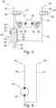
- the cable drum carrier 2 has a first hydraulic system 23, which Figure 3 is shown in a schematic representation.
- the hydraulic system 23 has a first actuator 24 which is operatively connected to the holding arms 7 and is arranged on the cross member 5 in order to move the holding arms 7 along the cross member 5.
- the hydraulic actuator 24 is designed as a hydraulic cylinder 25 which has a working cylinder 26 in which a piston 27 is mounted so as to be longitudinally displaceable, as indicated by a double arrow.
- the piston 27 is connected to one of the holding arms 7 by a piston rod 28 which protrudes from the front of the working cylinder 26.
- the working cylinder 26 is firmly connected to the other of the holding arms 7 at its end facing away from the piston rod 28.
- two working chambers 29 and 30 are formed in the working cylinder 26, which can be filled with hydraulic medium.
- the piston 27 is moved in one direction or the other in order to move the holding arms 7 towards or away from each other.
- the conveying direction of the hydraulic medium which is determined by the hydraulic supply system, determines which of the two working chambers 29, 30 is filled or pressurized with hydraulic pressure.
- at least one further controllable or actuatable valve device is present, by means of which one or the other of the working chambers 29, 30 can be supplied with the hydraulic medium.
- each of the holding arms 7 is assigned a hydraulic cylinder 25.
- the hydraulic cylinders 25 are arranged on opposite sides of the cross member 5.
- the working cylinders 26 are each firmly connected to the cross member 5 and the piston rods 28 to the respective holding arm 7.
- the hydraulic cylinders 25 are arranged in particular in opposite directions to each other on the cross member 5.
- the hydraulic cylinders 25 are each located in a lateral recess of the cross member 5 formed by the I-cross-sectional shape of the cross member 5, so that they are inserted into the cable drum carrier 2 in a space-saving manner.
- Figure 3 the second hydraulic cylinder 25 is only shown in a simplified manner, but is also integrated into the hydraulic system 23. The opposing arrangement of the hydraulic cylinders 25 on the cross member 5 ensures that the holding arms 7 are moved in opposite directions by the hydraulic system 23.
- the hydraulic system 23 has at least one hydraulic motor 31, which forms a second hydraulic actuator 32 of the cable drum carrier 2 and is assigned to one of the bearing pins 12 and is connected to it in a rotationally fixed manner directly or via a gear.
- the bearing pin 12 is driven to rotate in one direction or the other.
- the conveying direction depends on the hydraulic supply system.
- at least one valve or switching device is preferably present in the hydraulic system 23, by means of which a reversal of the flow direction can be set independently of the hydraulic supply system.
- the first hydraulic cylinders 25 are arranged in a first hydraulic circuit 33 and the hydraulic motor 31 in a second hydraulic circuit 34 of the hydraulic system 23.
- the two hydraulic circuits 33, 34 are each connected to two switching valves 35, 36.
- One switching valve 35 is connected on the input side to a hydraulic supply line 37 and the other of the switching valves 36 is connected on the output side to a hydraulic return line 38.
- the two switching valves 35, 36 are each designed as 2/3-way valves, i.e. as switching valves that have two switching positions and three connections. One of the connections is provided for the supply line 37 or for the return line 38.
- a second connection of the switching valve 35 is connected to the first hydraulic circuit 33, as is a second connection of the switching valve 36.
- a third connection of the switching valves 35 and 36 is connected to the second hydraulic circuit 34.
- the switching valve 35 connects the supply line 37 with the first hydraulic circuit 33 and the switching valve 36 connects the hydraulic circuit 33 with the return line 38. In this case, the first hydraulic circuit 33 is activated.
- the switching valve 35 connects the supply line 37 with the second hydraulic circuit 37 and the switching valve 36 connects the hydraulic circuit 34 with the return line 38. If the two switching valves 35, 36 are in the second switching position, the second hydraulic circuit 34 is hydraulically connected to the feed line or supply line 37 and return line 38 and is thus activated.
- none of the hydraulic circuits 33, 34 can be operated and the cable drum carrier 2 is preferably hydraulically blocked.
- the switching valves 35, 36 ensure that the holding arms 7 can only be moved when both switching valves 35, 36 are in the first switching position. This ensures that the cable drum 18 is protected from incorrect operation and unintentional detachment from the cable drum carrier 2.
- the second hydraulic circuit 34 has a throttle valve 39 connected upstream and/or downstream of the hydraulic motor 31, by means of which the hydraulic flow in the second hydraulic circuit 34 can be influenced in order to be able to adjust the rotational speed of the hydraulic motor 31 independently of the existing hydraulic pressure of a hydraulic supply system, in particular of the construction machine 3.
- the throttle valves 39 are arranged as manually operable throttle valves on the holding arms 7, so that a user can manually operate the respective throttle valve 39 by operating a respective handle 40.
- the switching valves 35, 36 are also preferably designed as manually operable switching valves, to which a handle 41 or 42 is assigned, by means of which the switching valves 35, 36 can be moved from one switching position to the other.
- the handles 41, 42 are also preferably arranged on the holding arm 7, in particular close to the end 11 of the holding arms 7 on the outside of the holding arms 7, i.e. on the side facing away from the opposite holding arm 7, so that they can be easily reached and operated by a user.
- the cable drum carrier 2 preferably has a second hydraulic system 43, which is shown schematically in Figure 4
- the second hydraulic system 43 has a further actuator 44 in the form of a hydraulic motor 45, which is assigned to the coupling 6, in particular to the rotary joint 22 of the coupling.
- the actuator 44 is designed to rotate the cross member 5 about the rotation axis 22' relative to the coupling 22 if necessary, as shown by a double arrow in Figure 2
- the hydraulic motor 45 is hydraulically connected to a supply line 46 and a return line 47.
- the supply lines 37, 46 and the return lines 38, 47 each end in a connection 48, 49 on the coupling 6, which is also designed to automatically connect the supply lines 37, 46 and return lines 38, 47 or the connections 48, 49 to a hydraulic supply system of the construction machine 3 when the cable drum carrier 2 is mechanically attached to the construction machine 3. This not only results in a mechanical but also a hydraulic coupling of the cable drum carrier 2 to the construction machine 3 in an automated manner.
- the hydraulic lines of the hydraulic systems 23, 43 can be manually connected to the hydraulic supply system of the construction machine 3 by a user.
Landscapes
- Engineering & Computer Science (AREA)
- Mechanical Engineering (AREA)
- Unwinding Of Filamentary Materials (AREA)
- Storage Of Web-Like Or Filamentary Materials (AREA)
Claims (14)
- Support d'enrouleur de câble (2) pour le montage en rotation d'un enrouleur de câble (18), avec un support transversal (5) sur lequel sont disposés deux bras de maintien (7) orientés parallèlement l'un à l'autre, dans lequel chaque bras de maintien (7) présente à une extrémité libre (11) à chaque fois un boulon d'appui (12) faisant saillie latéralement et monté en rotation, dans lequel les boulons d'appui (12) sont disposés en étant orientés l'un vers l'autre et d'une manière affleurante l'un par rapport à l'autre sur les bras de maintien (7) et sont orientés parallèlement au support transversal (5), et dans lequel au moins l'un des bras de maintien (7) est monté de manière à pouvoir coulisser le long du support transversal (5), avec un premier actionneur commandable (24), qui est disposé sur le support transversal (5) et avec au moins l'un des bras de maintien (7), plus particulièrement avec deux bras de maintien (7), au déplacement duquel ou desquels il est relié d'une manière opérationnelle, avec au moins un deuxième actionneur commandable (32), qui est relié d'une manière opérationnelle à au moins l'un des boulons d'appui (12), pour appliquer un couple à celui-ci pour le faire tourner autour de son axe central longitudinal (14), dans lequel le premier actionneur (24) et le deuxième actionneur (32) est conçu à chaque fois comme actionneur hydraulique, caractérisé par un premier système hydraulique (23) qui présente un premier circuit hydraulique (33) avec le premier actionneur (24) et un deuxième circuit hydraulique (34) avec le deuxième actionneur (32), et au moins une soupape de commutation (35, 36) par laquelle peut être relié au choix le premier circuit hydraulique (33) ou le deuxième circuit hydraulique (34) avec un raccord hydraulique (48, 49) pouvant être relié à un système d'alimentation hydraulique.
- Support d'enrouleur de câble selon la revendication 1, caractérisé en ce qu'un premier actionneur (24) est associé à chaque fois pour son déplacement à chacun des bras de maintien (7).
- Support d'enrouleur de câble selon l'une des revendications précédentes, caractérisé en ce que le premier actionneur (24) est conçu comme un cylindre hydraulique (25).
- Support d'enrouleur de câble selon l'une des revendications précédentes, caractérisé en ce que le deuxième actionneur (32) est conçu comme un moteur hydraulique (31).
- Support d'enrouleur de câble selon l'une des revendications précédentes, caractérisé en ce que le raccord hydraulique (48, 49) est disposé, vu en extension longitudinale du support transversal (5), entre les bras de maintien (7), plus particulièrement au milieu sur le support transversal (5).
- Support d'enrouleur de câble selon l'une des revendications précédentes, caractérisé en ce qu'est disposé sur le support transversal (5) un dispositif d'accouplement pouvant être actionné (6) pour la fixation mécanique détachable du support d'enrouleur de câble (2) à un bras de machine de travail (4), plus particulièrement d'une machine de chantier (3).
- Support d'enrouleur de câble selon la revendication 6, caractérisé par un deuxième système hydraulique (43) qui présente un troisième actionneur actionnable hydrauliquement (44), dans lequel le dispositif d'accouplement pouvant être actionné (6) est monté sur le support transversal (5) en pouvant tourner au moyen d'une articulation tournante (22), et dans lequel le troisième actionneur (44) est conçu pour déformer le dispositif d'accouplement (22) par rapport au support transversal (5) lors de sa commande.
- Support d'enrouleur de câble selon la revendication 7, caractérisé en ce que le deuxième système hydraulique (43) présente un raccord hydraulique (49) qui est associé au dispositif d'accouplement (6).
- Support d'enrouleur de câble selon la revendication 8, caractérisé en ce que le dispositif d'accouplement (6) est conçu pour produire, lors de la fixation mécanique du support d'enrouleur de câble (2) au moins une liaison hydraulique entre le système d'alimentation hydraulique et le premier et/ou le deuxième système hydraulique (23, 43).
- Support d'enrouleur de câble selon la revendication 8, caractérisé en ce que le premier système hydraulique (23) présente deux soupapes de commutation (35, 36) qui relient le premier circuit hydraulique (33) seulement ensuite au raccord hydraulique (48) lorsque les deux soupapes de commutation (35, 36) se trouvent dans une première de deux positions de commutation, et qui relient le deuxième circuit hydraulique (34) seulement ensuite au raccord hydraulique (48) lorsque les deux soupapes de commutation (35, 36) se trouvent dans une deuxième des deux positions de commutation.
- Support d'enrouleur de câble selon la revendication 10, caractérisé en ce que les deux soupapes de commutation (35, 36) sont des soupapes de commutation manuelles, dans lequel est disposée sur les bras de maintien (7) à chaque fois une poignée (41, 42) uniquement d'une des soupapes de commutation (35, 36).
- Support d'enrouleur de câble selon l'une des revendications précédentes, caractérisé en ce que dans le deuxième circuit hydraulique (34) est disposée au moins une soupape d'étranglement (39) utilisable en particulier manuellement.
- Support d'enrouleur de câble selon l'une des revendications précédentes, caractérisé en ce que sur le boulon d'appui respectif (12) est disposé d'une manière fixe en rotation à chaque fois un disque d'appui axial (13) pour l'appui axial d'un enrouleur de câble (18).
- Support d'enrouleur de câble selon la revendication 13, caractérisé en ce que le disque d'appui axial respectif (13) présente au moins un élément de butée (16) déformable élastiquement, plus particulièrement plusieurs éléments de butée (16), disposés en étant répartis uniformément sur la circonférence du disque d'appui axial (13), plus particulièrement des éléments élastomères, pour un enrouleur de câble (18).
Applications Claiming Priority (2)
| Application Number | Priority Date | Filing Date | Title |
|---|---|---|---|
| DE202020107393.1U DE202020107393U1 (de) | 2020-12-18 | 2020-12-18 | Kabeltrommelträger zur drehbaren Lagerung einer Kabeltrommel |
| PCT/EP2021/086422 WO2022129481A1 (fr) | 2020-12-18 | 2021-12-17 | Support d'enrouleur de câble pour supporter en rotation un enrouleur de câble |
Publications (3)
| Publication Number | Publication Date |
|---|---|
| EP4263407A1 EP4263407A1 (fr) | 2023-10-25 |
| EP4263407C0 EP4263407C0 (fr) | 2025-02-26 |
| EP4263407B1 true EP4263407B1 (fr) | 2025-02-26 |
Family
ID=74846318
Family Applications (1)
| Application Number | Title | Priority Date | Filing Date |
|---|---|---|---|
| EP21843594.9A Active EP4263407B1 (fr) | 2020-12-18 | 2021-12-17 | Support d'enrouleur de câble pour supporter en rotation un enrouleur de câble |
Country Status (6)
| Country | Link |
|---|---|
| US (1) | US12466690B2 (fr) |
| EP (1) | EP4263407B1 (fr) |
| CA (1) | CA3202613A1 (fr) |
| DE (1) | DE202020107393U1 (fr) |
| ES (1) | ES3024981T3 (fr) |
| WO (1) | WO2022129481A1 (fr) |
Families Citing this family (2)
| Publication number | Priority date | Publication date | Assignee | Title |
|---|---|---|---|---|
| US12428258B2 (en) * | 2022-10-03 | 2025-09-30 | Michael Birdwell | Method and apparatus for winding a cable |
| CN118495328B (zh) * | 2024-07-19 | 2024-09-24 | 河南东起机械有限公司 | 一种智能安全型电缆盘吊装吊具 |
Citations (4)
| Publication number | Priority date | Publication date | Assignee | Title |
|---|---|---|---|---|
| FR2492796A1 (fr) * | 1980-07-01 | 1982-04-30 | Telecommunications Sa | Palonnier pour la manutention de tourets ou bobines analogues |
| JPS63189352A (ja) * | 1987-01-30 | 1988-08-04 | Dainippon Printing Co Ltd | 巻取の前処理装置 |
| US20100314482A1 (en) * | 2006-11-17 | 2010-12-16 | Eric Merkt | Rolled turf layer |
| US20150217967A1 (en) * | 2014-02-05 | 2015-08-06 | Polypipe Handling Specialists, Inc. | Apparatus for deploying and retrieving hose |
Family Cites Families (20)
| Publication number | Priority date | Publication date | Assignee | Title |
|---|---|---|---|---|
| US3123314A (en) | 1960-03-28 | 1964-03-03 | bruestle | |
| SE399864B (sv) | 1976-03-29 | 1978-03-06 | Skaltek Ab | Anordning for upptagning eller avrullning av kabel, lina, vajer eller dylikt |
| US4252358A (en) | 1979-08-08 | 1981-02-24 | Klebs James P | Horizontal grapple |
| SE463308B (sv) | 1989-10-31 | 1990-11-05 | Skaltek Ab | Drivanordning foer rotation av kabeltrumman i maskiner foer upplindning och avrullning av kabel e d |
| US5938392A (en) * | 1997-03-11 | 1999-08-17 | Duck; Bennie H. | Spooled hay dispenser |
| IT1309918B1 (it) | 1999-08-05 | 2002-02-05 | Belotti Handling S P A | Veicolo per la movimentazione di coils o bobine, in particolare dilamiera,o simili. |
| CN2442424Y (zh) | 2000-09-07 | 2001-08-08 | 阎兴军 | 电缆滚起吊、收放线装置 |
| US7931133B2 (en) * | 2008-01-16 | 2011-04-26 | Soave Enterprises L.L.C. | System for self-adjusting height and direction of a movable power cable |
| DE202011100482U1 (de) | 2011-05-10 | 2012-08-13 | Kinshofer Gmbh | Drehschwenkantrieb für Anbauwerkzeuge |
| US8784007B2 (en) * | 2012-11-09 | 2014-07-22 | Walter N. Wilson | Apparatus for covering a land area with a heavy wide width flexible sheeting |
| US9676589B2 (en) * | 2014-04-04 | 2017-06-13 | Richard Lee Chachere | Device and method usable for installing cable into a winch spool |
| US9476269B2 (en) * | 2014-04-15 | 2016-10-25 | Peter E Dyck | Apparatus and method for pulling and laying poly pipe |
| GB2546471A (en) * | 2015-12-02 | 2017-07-26 | Faun Trackway Ltd | Deployment system |
| NO343018B1 (en) | 2016-08-25 | 2018-10-01 | Jack Pack As | A cable drum feeding tool for a vehicle with a lifting device |
| US10513412B2 (en) * | 2017-08-03 | 2019-12-24 | Harris Corporation | Automatic spool tensioning mechanism |
| CN108190612B (zh) | 2017-12-29 | 2019-11-19 | 曹诗晴 | 一种电线电缆的放线装置 |
| US11827489B1 (en) * | 2020-04-08 | 2023-11-28 | Con-Wal, Inc. | Interchangeable tarp deployment system |
| US11856892B2 (en) * | 2020-11-10 | 2024-01-02 | Theodore H. CORRIHER | Self-aligning hay bale unroller |
| US12515911B2 (en) * | 2022-10-05 | 2026-01-06 | Vavricka Development Trust | System for using a digger vehicle to reel wire |
| WO2024254221A1 (fr) * | 2023-06-05 | 2024-12-12 | Flanders Electric Motor Service, Llc | Système de gestion de câble de piste de forage |
-
2020
- 2020-12-18 DE DE202020107393.1U patent/DE202020107393U1/de active Active
-
2021
- 2021-12-17 CA CA3202613A patent/CA3202613A1/fr active Pending
- 2021-12-17 ES ES21843594T patent/ES3024981T3/es active Active
- 2021-12-17 US US18/257,996 patent/US12466690B2/en active Active
- 2021-12-17 WO PCT/EP2021/086422 patent/WO2022129481A1/fr not_active Ceased
- 2021-12-17 EP EP21843594.9A patent/EP4263407B1/fr active Active
Patent Citations (4)
| Publication number | Priority date | Publication date | Assignee | Title |
|---|---|---|---|---|
| FR2492796A1 (fr) * | 1980-07-01 | 1982-04-30 | Telecommunications Sa | Palonnier pour la manutention de tourets ou bobines analogues |
| JPS63189352A (ja) * | 1987-01-30 | 1988-08-04 | Dainippon Printing Co Ltd | 巻取の前処理装置 |
| US20100314482A1 (en) * | 2006-11-17 | 2010-12-16 | Eric Merkt | Rolled turf layer |
| US20150217967A1 (en) * | 2014-02-05 | 2015-08-06 | Polypipe Handling Specialists, Inc. | Apparatus for deploying and retrieving hose |
Also Published As
| Publication number | Publication date |
|---|---|
| WO2022129481A1 (fr) | 2022-06-23 |
| DE202020107393U1 (de) | 2021-02-15 |
| EP4263407C0 (fr) | 2025-02-26 |
| US20240051783A1 (en) | 2024-02-15 |
| CA3202613A1 (fr) | 2022-06-23 |
| US12466690B2 (en) | 2025-11-11 |
| ES3024981T3 (en) | 2025-06-05 |
| EP4263407A1 (fr) | 2023-10-25 |
Similar Documents
| Publication | Publication Date | Title |
|---|---|---|
| EP1950353B1 (fr) | Dispositif d'excavation du sol | |
| DE3890753C2 (de) | Apparat zum Drehen eines rohrförmigen Bohrungselements um seine Längsachse | |
| DE69515809T2 (de) | Fahrgestell mit verstellbarer Spurbreite | |
| EP0182091B1 (fr) | Elévateur de puissance pour un dispositif de levage | |
| EP4263407B1 (fr) | Support d'enrouleur de câble pour supporter en rotation un enrouleur de câble | |
| DE102012110917A1 (de) | Ultraschall-Prüfeinrichtung mit flexibler Prüfkopfhalterung | |
| DE10392209B4 (de) | Verfahren und Vorrichtung zum Ziehen eines Seils durch einen Rohrabschnitt | |
| DE69001771T2 (de) | Anordnung zur Handhabung von Bohrstangen in einem Gesteinsbohraggregat oder dgl. | |
| EP2540613B1 (fr) | Dispositif de raccordement pour un conduit d'alimentation | |
| DE102020216285A1 (de) | Kabeltrommelträger zur drehbaren Lagerung einer Kabeltrommel | |
| DE102016225211B4 (de) | Teleskop-Ausleger und Kran mit Teleskop-Ausleger | |
| EP3800299B1 (fr) | Équipement, en particulier chargeur sur roues | |
| EP3951128B1 (fr) | Dispositif de dégagement d'un espace intermédiaire hélicoïdal d'une tarière et procédé pour créer un alésage | |
| DE19813854A1 (de) | Vorrichtung zur Herstellung von Quetschverbindungen | |
| EP4457119B1 (fr) | Siège pliant pour véhicule | |
| EP2287513B1 (fr) | Dispositif et procédé de déplacement d'un moyen de travail dans la terre | |
| DE2921048A1 (de) | Ventilbetaetigungssystem | |
| DE102007026985B4 (de) | Vorrichtung zum automatischen Ankuppeln eines Gießlöffels | |
| DE102018127295A1 (de) | Vorrichtung zum Leiten von Hydraulikflüssigkeit | |
| DE10302194B3 (de) | Vorrichtung und Verfahren zum Einziehen einer Leitung oder eines Bohrwerkzeugs in einen Kanal | |
| DE19842765A1 (de) | Vorrichtung zur Herstellung von Quetschverbindungen | |
| DE2750371A1 (de) | Arbeitsmaschine mit zwei arbeitsgeraeten | |
| DE10332328B3 (de) | Vorrichtung zum Erneuern von im Erdreich verlegten Versorgungsleitungen | |
| DE202008015436U1 (de) | Vorrichtung zum Materialtransport | |
| EP4520871A1 (fr) | Excavateur |
Legal Events
| Date | Code | Title | Description |
|---|---|---|---|
| STAA | Information on the status of an ep patent application or granted ep patent |
Free format text: STATUS: UNKNOWN |
|
| STAA | Information on the status of an ep patent application or granted ep patent |
Free format text: STATUS: THE INTERNATIONAL PUBLICATION HAS BEEN MADE |
|
| PUAI | Public reference made under article 153(3) epc to a published international application that has entered the european phase |
Free format text: ORIGINAL CODE: 0009012 |
|
| STAA | Information on the status of an ep patent application or granted ep patent |
Free format text: STATUS: REQUEST FOR EXAMINATION WAS MADE |
|
| 17P | Request for examination filed |
Effective date: 20230718 |
|
| AK | Designated contracting states |
Kind code of ref document: A1 Designated state(s): AL AT BE BG CH CY CZ DE DK EE ES FI FR GB GR HR HU IE IS IT LI LT LU LV MC MK MT NL NO PL PT RO RS SE SI SK SM TR |
|
| DAV | Request for validation of the european patent (deleted) | ||
| DAX | Request for extension of the european patent (deleted) | ||
| STAA | Information on the status of an ep patent application or granted ep patent |
Free format text: STATUS: EXAMINATION IS IN PROGRESS |
|
| 17Q | First examination report despatched |
Effective date: 20240701 |
|
| GRAP | Despatch of communication of intention to grant a patent |
Free format text: ORIGINAL CODE: EPIDOSNIGR1 |
|
| STAA | Information on the status of an ep patent application or granted ep patent |
Free format text: STATUS: GRANT OF PATENT IS INTENDED |
|
| INTG | Intention to grant announced |
Effective date: 20240923 |
|
| GRAS | Grant fee paid |
Free format text: ORIGINAL CODE: EPIDOSNIGR3 |
|
| GRAA | (expected) grant |
Free format text: ORIGINAL CODE: 0009210 |
|
| STAA | Information on the status of an ep patent application or granted ep patent |
Free format text: STATUS: THE PATENT HAS BEEN GRANTED |
|
| AK | Designated contracting states |
Kind code of ref document: B1 Designated state(s): AL AT BE BG CH CY CZ DE DK EE ES FI FR GB GR HR HU IE IS IT LI LT LU LV MC MK MT NL NO PL PT RO RS SE SI SK SM TR |
|
| REG | Reference to a national code |
Ref country code: GB Ref legal event code: FG4D Free format text: NOT ENGLISH |
|
| REG | Reference to a national code |
Ref country code: CH Ref legal event code: EP |
|
| REG | Reference to a national code |
Ref country code: DE Ref legal event code: R096 Ref document number: 502021006820 Country of ref document: DE |
|
| REG | Reference to a national code |
Ref country code: IE Ref legal event code: FG4D Free format text: LANGUAGE OF EP DOCUMENT: GERMAN |
|
| U01 | Request for unitary effect filed |
Effective date: 20250326 |
|
| U07 | Unitary effect registered |
Designated state(s): AT BE BG DE DK EE FI FR IT LT LU LV MT NL PT RO SE SI Effective date: 20250401 |
|
| REG | Reference to a national code |
Ref country code: ES Ref legal event code: FG2A Ref document number: 3024981 Country of ref document: ES Kind code of ref document: T3 Effective date: 20250605 |
|
| PG25 | Lapsed in a contracting state [announced via postgrant information from national office to epo] |
Ref country code: RS Free format text: LAPSE BECAUSE OF FAILURE TO SUBMIT A TRANSLATION OF THE DESCRIPTION OR TO PAY THE FEE WITHIN THE PRESCRIBED TIME-LIMIT Effective date: 20250526 |
|
| PG25 | Lapsed in a contracting state [announced via postgrant information from national office to epo] |
Ref country code: PL Free format text: LAPSE BECAUSE OF FAILURE TO SUBMIT A TRANSLATION OF THE DESCRIPTION OR TO PAY THE FEE WITHIN THE PRESCRIBED TIME-LIMIT Effective date: 20250226 |
|
| PG25 | Lapsed in a contracting state [announced via postgrant information from national office to epo] |
Ref country code: IS Free format text: LAPSE BECAUSE OF FAILURE TO SUBMIT A TRANSLATION OF THE DESCRIPTION OR TO PAY THE FEE WITHIN THE PRESCRIBED TIME-LIMIT Effective date: 20250626 Ref country code: NO Free format text: LAPSE BECAUSE OF FAILURE TO SUBMIT A TRANSLATION OF THE DESCRIPTION OR TO PAY THE FEE WITHIN THE PRESCRIBED TIME-LIMIT Effective date: 20250526 |
|
| PG25 | Lapsed in a contracting state [announced via postgrant information from national office to epo] |
Ref country code: HR Free format text: LAPSE BECAUSE OF FAILURE TO SUBMIT A TRANSLATION OF THE DESCRIPTION OR TO PAY THE FEE WITHIN THE PRESCRIBED TIME-LIMIT Effective date: 20250226 |
|
| PG25 | Lapsed in a contracting state [announced via postgrant information from national office to epo] |
Ref country code: GR Free format text: LAPSE BECAUSE OF FAILURE TO SUBMIT A TRANSLATION OF THE DESCRIPTION OR TO PAY THE FEE WITHIN THE PRESCRIBED TIME-LIMIT Effective date: 20250527 |
|
| PG25 | Lapsed in a contracting state [announced via postgrant information from national office to epo] |
Ref country code: SM Free format text: LAPSE BECAUSE OF FAILURE TO SUBMIT A TRANSLATION OF THE DESCRIPTION OR TO PAY THE FEE WITHIN THE PRESCRIBED TIME-LIMIT Effective date: 20250226 |
|
| PG25 | Lapsed in a contracting state [announced via postgrant information from national office to epo] |
Ref country code: CZ Free format text: LAPSE BECAUSE OF FAILURE TO SUBMIT A TRANSLATION OF THE DESCRIPTION OR TO PAY THE FEE WITHIN THE PRESCRIBED TIME-LIMIT Effective date: 20250226 |
|
| PG25 | Lapsed in a contracting state [announced via postgrant information from national office to epo] |
Ref country code: SK Free format text: LAPSE BECAUSE OF FAILURE TO SUBMIT A TRANSLATION OF THE DESCRIPTION OR TO PAY THE FEE WITHIN THE PRESCRIBED TIME-LIMIT Effective date: 20250226 |
|
| PLBE | No opposition filed within time limit |
Free format text: ORIGINAL CODE: 0009261 |
|
| REG | Reference to a national code |
Ref country code: CH Ref legal event code: U11 Free format text: ST27 STATUS EVENT CODE: U-0-0-U10-U11 (AS PROVIDED BY THE NATIONAL OFFICE) Effective date: 20260101 |
|
| STAA | Information on the status of an ep patent application or granted ep patent |
Free format text: STATUS: NO OPPOSITION FILED WITHIN TIME LIMIT |
|
| 26N | No opposition filed |
Effective date: 20251127 |
|
| U20 | Renewal fee for the european patent with unitary effect paid |
Year of fee payment: 5 Effective date: 20251230 |
|
| PGFP | Annual fee paid to national office [announced via postgrant information from national office to epo] |
Ref country code: ES Payment date: 20260130 Year of fee payment: 5 |
|
| PGFP | Annual fee paid to national office [announced via postgrant information from national office to epo] |
Ref country code: CH Payment date: 20260101 Year of fee payment: 5 |