EP4263884B1 - Feuille d'aluminium à propriétés de barrière améliorées - Google Patents
Feuille d'aluminium à propriétés de barrière améliorées Download PDFInfo
- Publication number
- EP4263884B1 EP4263884B1 EP21839200.9A EP21839200A EP4263884B1 EP 4263884 B1 EP4263884 B1 EP 4263884B1 EP 21839200 A EP21839200 A EP 21839200A EP 4263884 B1 EP4263884 B1 EP 4263884B1
- Authority
- EP
- European Patent Office
- Prior art keywords
- aluminium alloy
- alloy foil
- foil
- rolling
- aluminum alloy
- Prior art date
- Legal status (The legal status is an assumption and is not a legal conclusion. Google has not performed a legal analysis and makes no representation as to the accuracy of the status listed.)
- Active
Links
Images

Classifications
-
- C—CHEMISTRY; METALLURGY
- C22—METALLURGY; FERROUS OR NON-FERROUS ALLOYS; TREATMENT OF ALLOYS OR NON-FERROUS METALS
- C22C—ALLOYS
- C22C21/00—Alloys based on aluminium
-
- B—PERFORMING OPERATIONS; TRANSPORTING
- B22—CASTING; POWDER METALLURGY
- B22D—CASTING OF METALS; CASTING OF OTHER SUBSTANCES BY THE SAME PROCESSES OR DEVICES
- B22D11/00—Continuous casting of metals, i.e. casting in indefinite lengths
- B22D11/001—Continuous casting of metals, i.e. casting in indefinite lengths of specific alloys
- B22D11/003—Aluminium alloys
-
- C—CHEMISTRY; METALLURGY
- C21—METALLURGY OF IRON
- C21D—MODIFYING THE PHYSICAL STRUCTURE OF FERROUS METALS; GENERAL DEVICES FOR HEAT TREATMENT OF FERROUS OR NON-FERROUS METALS OR ALLOYS; MAKING METAL MALLEABLE, e.g. BY DECARBURISATION OR TEMPERING
- C21D8/00—Modifying the physical properties of ferrous metals or ferrous alloys by deformation combined with, or followed by, heat treatment
- C21D8/02—Modifying the physical properties of ferrous metals or ferrous alloys by deformation combined with, or followed by, heat treatment during manufacturing of plates or strips
- C21D8/0221—Modifying the physical properties of ferrous metals or ferrous alloys by deformation combined with, or followed by, heat treatment during manufacturing of plates or strips characterised by the working steps
- C21D8/0236—Cold rolling
-
- C—CHEMISTRY; METALLURGY
- C21—METALLURGY OF IRON
- C21D—MODIFYING THE PHYSICAL STRUCTURE OF FERROUS METALS; GENERAL DEVICES FOR HEAT TREATMENT OF FERROUS OR NON-FERROUS METALS OR ALLOYS; MAKING METAL MALLEABLE, e.g. BY DECARBURISATION OR TEMPERING
- C21D8/00—Modifying the physical properties of ferrous metals or ferrous alloys by deformation combined with, or followed by, heat treatment
- C21D8/02—Modifying the physical properties of ferrous metals or ferrous alloys by deformation combined with, or followed by, heat treatment during manufacturing of plates or strips
- C21D8/0247—Modifying the physical properties of ferrous metals or ferrous alloys by deformation combined with, or followed by, heat treatment during manufacturing of plates or strips characterised by the heat treatment
- C21D8/0268—Modifying the physical properties of ferrous metals or ferrous alloys by deformation combined with, or followed by, heat treatment during manufacturing of plates or strips characterised by the heat treatment between cold rolling steps
-
- C—CHEMISTRY; METALLURGY
- C21—METALLURGY OF IRON
- C21D—MODIFYING THE PHYSICAL STRUCTURE OF FERROUS METALS; GENERAL DEVICES FOR HEAT TREATMENT OF FERROUS OR NON-FERROUS METALS OR ALLOYS; MAKING METAL MALLEABLE, e.g. BY DECARBURISATION OR TEMPERING
- C21D8/00—Modifying the physical properties of ferrous metals or ferrous alloys by deformation combined with, or followed by, heat treatment
- C21D8/02—Modifying the physical properties of ferrous metals or ferrous alloys by deformation combined with, or followed by, heat treatment during manufacturing of plates or strips
- C21D8/0247—Modifying the physical properties of ferrous metals or ferrous alloys by deformation combined with, or followed by, heat treatment during manufacturing of plates or strips characterised by the heat treatment
- C21D8/0273—Final recrystallisation annealing
-
- C—CHEMISTRY; METALLURGY
- C22—METALLURGY; FERROUS OR NON-FERROUS ALLOYS; TREATMENT OF ALLOYS OR NON-FERROUS METALS
- C22F—CHANGING THE PHYSICAL STRUCTURE OF NON-FERROUS METALS AND NON-FERROUS ALLOYS
- C22F1/00—Changing the physical structure of non-ferrous metals or alloys by heat treatment or by hot or cold working
- C22F1/04—Changing the physical structure of non-ferrous metals or alloys by heat treatment or by hot or cold working of aluminium or alloys based thereon
Definitions
- the invention relates to an aluminum alloy foil with a thickness of maximum 12 ⁇ m, maximum 9 ⁇ m or less than 8 ⁇ m, wherein the aluminum alloy foil comprises an AA1xxx or A8xxx aluminum alloy in the material state H2x or O.
- the invention relates to a method for producing an aluminum alloy foil and its use.
- Aluminum alloy foils with the thicknesses mentioned are often used in food packaging, where they are, for example, a component of multilayer composite materials.
- the aluminum alloy foils contained in multilayer composite materials are used primarily because of their good barrier properties.
- aluminum alloy foil has a very good barrier effect, for example for water vapor, oxygen, carbon dioxide and larger molecules such as flavors. This is achieved by the crystalline structure of the aluminum alloy foil, which essentially prevents solubility and diffusion of larger atoms through the crystal structure.
- Material transport through the aluminum alloy foil is only possible at defects in an aluminum alloy foil, for example at pores or holes. Pores are tiny openings in aluminum alloy foils that can be detected by the local passage of light through the foil.
- pores in an aluminum alloy foil are randomly distributed holes with a maximum diameter of 200 ⁇ m. According to a definition in DIN EN 546-4, holes are considered rolling holes from 200 ⁇ m. It was previously known that the porosity of aluminum alloy foils increases with decreasing thickness. Pores can have a number of different causes. Inclusions or impurities in the molten metal, for example those from refractory materials or coarse cast phases (e.g. Al 3 Fe) can fall out of the rolled material during rolling and Rolling holes are left in the aluminum alloy foil. If the particles enclosed in the metal are particularly brittle, such as Al 3 Fe phases, these can also shatter during rolling and tiny fragments can be rolled into the rolled material.
- refractory materials or coarse cast phases e.g. Al 3 Fe
- aluminum alloy foils can also have micropores with a size of significantly less than 20 ⁇ m, in particular with a size of 1 ⁇ m to 5 ⁇ m, which can occur in very large numbers, locally limited in so-called "populations" that typically extend in the rolling direction of the aluminum alloy foil.
- the pores referred to as micropores can also have a negative effect on the barrier properties of the aluminum alloy foil.
- a necessary process in the production of aluminum alloy foils for the production of multilayer composite materials is the final annealing to degrease the rolled aluminum alloy foil.
- Rolling oil emulsions and rolling oils are used when rolling aluminum alloy strips and foils. Their residues must be removed from the foil after rolling so that important properties of the aluminum alloy foil for processing into multilayer materials, such as adhesive properties and wetting properties, have a predetermined level.
- the foils are wound into a coil or a ready-made roll and annealed as a coil or roll.
- the rolling media present on the aluminum alloy foil must essentially be removed as completely as possible from the coil or roll by decomposition and evaporation.
- the temperature treatment puts the aluminum alloy foil into either the partially hard material state H2x or the soft-annealed material state O.
- DIN EN 546-4 only covers pores with a minimum size of 20 ⁇ m. Pores with a size of less than 20 ⁇ m are not covered by DIN EN 546-4. In practice, most pores are round or oval with irregular edges.
- the area of the pore is determined in transmitted light under the microscope by imaging the exact outline with the sharpest possible edges and from this an area-equivalent circle diameter is calculated.
- the rolled films are tested using a light box. The film sample is placed on the light box; in the case of a double-rolled film, the matt side is turned towards the tester. The test takes place according to DIN EN 546-4 in a darkened room with a remaining maximum illuminance of 20 to 50 lux.
- a translucent glass plate is used as a light box, which is illuminated from below with the help of a light source that provides a uniform illuminance of 1000 to 1500 lux.
- the porosity can be measured in such a way that a 1 dm 2 measuring surface is selected from a larger film surface, which has the highest porosity and thus represents the worst measuring surface on the film.
- the number of pores determined on this measuring surface according to DIN EN 546-4 was determined as a measure of the porosity.
- the present invention is therefore based on the object of proposing an aluminum alloy foil with improved barrier properties, a process for its production and an inventive use of the aluminum alloy foil.
- the aluminum alloy foil has a maximum number of pores with a pore size of 1 ⁇ m to 200 ⁇ m of a maximum of 12 per dm 2 , a maximum of 8 per dm 2 or a maximum of 6 per dm 2 .
- the aluminum alloy foils according to the invention are therefore particularly suitable for use as a barrier layer, for example in a multilayer composite material.
- Pores with a size of 1 ⁇ m to 20 ⁇ m, in particular 1 ⁇ m to 5 ⁇ m, are common in conventional aluminium alloy foils in rolling direction extending, spatially limited, so-called “populations". In these populations, however, there are very many micropores.
- the maximum number of pores per dm 2 with a pore size of 1 ⁇ m to 200 ⁇ m is determined by dividing the aluminum alloy foil across the entire width of the foil into 5 to 6 dm 2 measuring surfaces with an edge length of 100 mm to 320 mm transverse to the rolling direction of the aluminum alloy foil, so that at least 3, preferably at least 5 measuring surfaces are obtained across the entire width of the aluminum alloy foil.
- the number of pores with a pore size of 1 ⁇ m to 200 ⁇ m is then determined in each measuring surface and the maximum number of pores per dm 2 is determined from the measuring surface with the highest number of pores per measuring surface by dividing by the selected size of the measuring surface and rounded to a whole number of pores.
- the maximum number of pores is measured after final annealing in the material state H2x or O, for example on coils or ready-made rolls.
- finished means that the aluminium alloy foil has already been cut to size, at least in width, for later use.
- the parameter of the maximum number of pores per dm 2 according to the present invention also covers micropores which can occur locally in clusters with a size of 1 ⁇ m to 20 ⁇ m, in so-called populations. As already explained, these populations often extend in the rolling direction of the aluminum alloy foil and are only found in a locally limited manner in certain areas of the aluminum alloy foil. When determining the maximum number of pores per dm 2 according to the present invention, however, these populations of micropores are reliably covered, since the entire width of the foil is taken into account.
- the aluminum alloy foil according to the invention with a maximum number of pores of a maximum of 12, a maximum of 8 or preferably a maximum of 6 per dm 2 is therefore almost free of micropores and thus provides particularly good barrier properties.
- the number of pores is measured in a completely darkened room with a residual illuminance of less than 0.25 lux.
- the area of the aluminum alloy foil to be measured is placed on a transparent glass surface and fixed with a frame whose inner dimensions correspond to the measuring surface.
- a light source with as even an illumination of the measuring surface as possible is arranged below the glass plate.
- the foil is fixed over the frame in such a way that the measuring surface is fixed on the aluminum alloy foil and essentially no residual light from the light source is emitted past the foil.
- the edges of the foil must be completely darkened.
- a flat light source with an illuminance of at least 15,000 lux can be used as a light source with a glass plate.
- the measuring surface is photographed with a digital camera centered over the measuring surface.
- An exposure time of 30 s with an ISO value of 800 or more should be used in order to be able to record the light passing through the smallest pores with a size of 1 ⁇ m to 20 ⁇ m.
- the distance of the camera should be chosen so that the measuring surface is completely recorded. However, the distance should be as small as possible.
- the number of pores with a size of 1 ⁇ m to 200 ⁇ m on the photographed measuring surface of the aluminum alloy foil should then be digitally evaluated using image analysis software.
- this test method can also be used to measure micropores with a pore size of 1 ⁇ m and more.
- the results showed that pores with a pore size of less than 20 ⁇ m, in particular less than 5 ⁇ m, can significantly impair the barrier properties of the aluminum alloy foil.
- the reason for this is seen in the locally limited, population-like occurrence of micropores with a high pore density. In narrowly defined areas of the aluminum alloy foil, a large number of micropores can therefore be present, which locally significantly reduce the barrier properties of the aluminum alloy foil.
- the aluminum alloy foils according to the invention with a maximum number of pores per dm 2 of a maximum of 12, maximum 8 or maximum 6 of pores with a pore size of 1 ⁇ m to 200 ⁇ m have particularly good barrier properties, since they do not have areas with high micropore density.
- the melt can be filtered before and/or during the casting of the rolling ingot and passed through appropriate filters to keep non-metallic inclusions out of the alloy.
- the cleaning of the melt should begin in the furnace. This removes some of the impurities early on before casting and saves costs.
- the melt can be cleaned by gas flushing with Ar, N 2 , by salt treatments and by allowing it to stand. These measures are often combined for the purpose of effective melt cleaning.
- the impurities are transported to the melt surface with the help of gas bubbles and absorbed by the dross. After a standing time, the accumulated impurities are scraped off.
- in-line cleaning processes such as degassers and filters can be used on the way from the furnace to the molds.
- the degassers work with a purge gas, for example the above-mentioned purge gases Ar, N 2 .
- the purge gases also have additional filter/flotation effects that can remove particle-like inclusions or oxide skins, for example.
- the purge gases are usually introduced via rotors in order to generate fine gas bubbles and thereby further improve the degassing and filtering effect.
- the degassers can be equipped with more than one treatment chamber, so that a series connection of several degassers in one unit can be used. At the outlet of these degassers with several treatment chambers, a chamber for standing the A melt must be provided in which remaining bubbles and inclusions can migrate to the strip surface and thus be removed from the melt.
- Foam ceramic filters such as CFF foam ceramic plate filters and deep bed filters
- a casting plant with a furnace for 70t can be equipped with an in-line degasser of the SIR filter type between the furnace and the casting plant and a degasser from HYCAST for a throughput of 50t/h as well as a downstream CFF foam ceramic plate filter with a pore size finer than 40 ppi ("pores per inch").
- the CFF foam ceramic filter plate is used as a disposable filter and replaced after each casting.
- a deep bed filter also known as a packed bed filter, can be used.
- the filter medium consists of alternating beds of balls and ball fragments made of tabular alumina with a diameter of up to approx. 20mm, for example, which are layered in a filter box of approx. 2 ⁇ 3m.
- homogenization of the cast rolling ingot at the temperatures and durations specified for the specific alloy types additionally leads to a reduction of coarse cast phases in the rolling ingot, for example coarse Al 3 Fe cast phases, and thus to the avoidance of correspondingly brittle particles in the very thinly rolled aluminum alloy foils.
- CC casting continuous strip casting process
- TRC twin roll caster
- the molten metal is fed to water-cooled rollers, where it solidifies.
- the solidified strip is then immediately rolled further.
- the melt goes through the same cleaning steps in the furnace as in the case of DC casting. This removes phases that are foreign to the material, such as carbides and oxides.
- the strips produced in CC casting tend to form so-called center segregations, which either take the form of coarse intermetallic phases, e.g. AlFe phases in the case of AlFeSi alloys, or in the form of enrichments of other alloying elements.
- the composition of the precipitates depends on the respective composition of the alloy and the selected parameters of the casting process.
- the composition of the AlFeSi alloy influences the width of the temperature interval at which the melt solidifies, which is also called the solidification interval. The wider the solidification interval, the greater the tendency for the middle segregations to form.
- the casting speed in the TRC process for example, varies between 1000 and 2500 mm/min.
- the cooling capacity is influenced by the outer diameter of the rollers. The larger the outer diameter, the higher the cooling capacity.
- a casting speed of 1000 to a maximum of 1500 mm/min with a roller diameter of approx. 600 mm can be selected.
- purer aluminum alloys such as type AA1050 or AA1070, however, a higher casting speed of 2000 to 2500 mm/min with a roll diameter of approx. 900 mm is advantageous in order to counteract center segregation.
- degreasing takes place through an annealing process to provide the material state H2x and O.
- the degreasing process by annealing the rolled aluminum alloy foil can have a major influence on the presence of pores with a pore size of 1 ⁇ m to 20 ⁇ m.
- the formation of micropores could be significantly reduced by reducing the annealing temperature to a maximum of 245 °C while simultaneously extending the annealing time and taking into account a special cooling phase of a maximum of 3 hours at 100 °C.
- the aluminum alloy foil according to the invention is characterized in that the aluminum alloy foil has an oxide layer thickness of 3 to 6 nm measured along the entire width of the Aluminum alloy foil, the oxide layer thickness of the aluminum alloy foil at the edge region of the aluminum alloy foil being a maximum of 30% greater than in the middle of the aluminum alloy foil. Not only is the oxide layer thickness particularly thin at 3 to 6 nm, it is homogeneous across the width of the aluminum alloy foil and only increases slightly towards the edge regions. The reason for this advantageous property of the aluminum alloy foil according to the invention is seen in the specific degreasing annealing with subsequent cooling process. This achieves more uniform surface properties for use in a multi-layer composite material.
- the uniform oxide layer thickness distribution keeps the adhesive properties of the foil particularly constant across the entire width.
- the layer thickness of the aluminum oxide layer can be measured, for example, by ATR (attenuated total reflection) infrared spectroscopy. With this measuring method, the oxide layer thickness can be recorded across the entire thickness with a resolution in the subnanometer range.
- the oxide layer thickness is a maximum of 5 nm on both the matte and glossy sides of the aluminum alloy foil.
- the reduced thickness of the oxide layer due to the manufacturing process leads to better adhesion properties of the surface of the aluminum alloy foil and thus to a good suitability of the aluminum alloy foil for a multilayer composite material, for example for packaging materials, for example as part of a flat bag packaging.
- AlFeSi alloys are significantly influenced by the elements in solution as well as by the binary AlFe and ternary AlFeSi phases.
- an Al solid solution supersaturated with Si and Fe is formed. Due to the low solubility, Fe is precipitated as an intermetallic compound Al3Fe and deposited at the grain boundaries of the Al solid solution.
- This binary phase is stable and hardly changes during the subsequent thermomechanical treatment.
- AlFe phases are only broken down in the rolling process under the influence of the rolling forces.
- the equilibrium solubility of Fe in aluminum is low and is max. 400 ppm (655°C).
- the maximum solubility of Si is significantly higher and is 1.65 wt% (577°C).
- Strength and elongation are positively influenced by the addition of Si.
- Silicon forms AlFeSi dispersoids and thus contributes to an increase in strength due to particle hardening and to an increase in elongation.
- the Si atoms in solution in the Al matrix contribute to solid solution hardening.
- the silicon-containing AlFeSi precipitates also represent nucleation centers for recrystallization and therefore improve the recrystallization properties of the aluminum alloy foil.
- the Si content is preferably limited to a maximum of 0.30 wt.%.
- the Si content is preferably at least 0.05 wt.%.
- Iron in solution also leads to an increase in strength, with a finer grain size and an increase in the thermal stability of the aluminum alloy foil, so that at least 0.7 wt.% iron is preferably contained.
- Fe contents of less than 0.7 wt.% reduce the proportion of iron in solution and result in a low phase density, so that the strength of the aluminum alloy foil is reduced.
- iron has a rather low solubility in the aluminum matrix and forms AlFe intermetallic phases when solidifying from the cast. These precipitates are coarse and rather detrimental to the mechanical properties.
- the iron content is therefore limited to 1.3 wt.%.
- Titanium acts as a grain refiner and leads to a slight increase in strength and recrystallization temperature.
- the aluminum alloy foil contains a maximum of 0.025 wt.% titanium.
- the weight proportions of Si and Fe are chosen so that an optimal Fe solution state with an optimal AlFe, AlFeSi phase density and thus the optimal strength parameters can be set in the manufacturing process adapted to the foil product requirements.
- the strength and thermal stability of the aluminum alloy foil increase again.
- coarsening of the grain structure is counteracted.
- Exceeding 1.15 wt.% Fe leads to a higher density of intermetallic AlFe cast phases and thus to a reduction in elongation and deterioration in porosity.
- the manganese content of the aluminum alloy in wt.% is preferably 0.01% ⁇ Mn ⁇ 0.04%, preferably 0.015% ⁇ Mn ⁇ 0.035%, particularly preferably 0.018% ⁇ Mn ⁇ 0.025%.
- a Mn content of less than 0.01 wt.% the strength and thermal stability of the aluminum alloy foil are reduced.
- contents of more than 400 ppm manganese on the other hand, the rolling force during foil rolling increases and thus also the process costs. A good compromise between increased strength and process costs is therefore achieved with contents of 0.0150 wt.% to 0.035 wt.%, preferably 0.018 wt.% to 0.025 wt.%.
- the element Mg is characterized by very good diffusion in the Al matrix and therefore tends to accumulate on the film surface. Therefore, the Mg content is limited to a maximum of 0.01 wt.%, preferably a maximum of 0.005 wt.%, particularly preferably a maximum of 0.0035 wt.%. Compliance with these values ensures that Mg accumulation on the film surface does not lead to the undesirable formation of magnesium oxide or magnesium hydroxide products in the Temperature influences in the customer process have adverse effects on the adhesion of coatings.
- the Zn content is preferably limited to a maximum of 0.07 wt.% in order to reduce the rolling forces during foil rolling.
- Cr and Ti are only present in small amounts in the aluminum alloy.
- the Cr content is limited to a maximum of 0.02% by weight.
- Cr is highly soluble in the aluminum matrix and even at low levels leads to a significant increase in the rolling force during foil rolling.
- Ti is limited to a maximum weight proportion of 250 ppm, whereby a minimum content of at least 50 ppm Ti leads to better castability and good mechanical properties at the same time. This avoids the additional costs caused by the unnecessarily high addition of alloying elements and also ensures that the foil yield stress and thus also the rolling forces do not exceed the limits specified in the foil rolling process.
- the aluminum alloy foil according to the invention in material state O it has a yield strength Rp0.2 measured transversely, longitudinally or diagonally to the rolling direction of at least 55 MPa, preferably at least 58 MPa.
- Rp0.2 measured transversely, longitudinally or diagonally to the rolling direction of at least 55 MPa, preferably at least 58 MPa.
- the aluminum alloy foil according to the invention is very good for processing into multilayer composite materials.
- the aluminum alloy foil according to the invention also shows an improvement in terms of the carbon content of the aluminum alloy foil, i.e. the amount of carbon from the rolling media that remains on the aluminum alloy foil after final annealing.
- the carbon content in the middle of the aluminum alloy foil is 20% lower than in the edge areas of the aluminum alloy foil. The differences here are usually across the Bandwidth between edge and middle areas of the aluminum alloy foil is significantly larger. Due to the more homogeneous C coverage across the width of the foil, the aluminum alloy foil according to the invention also has more uniform properties, for example adhesive properties.
- the C content of the aluminum alloy foil 5 cm wide strips of foil in the gram range are cut lengthwise from the annealed foil coil or from the annealed foil roll, wound up, precisely weighed and burned at 600°C in a quartz tube in an oxygen stream.
- the CO2 produced from rolling oil and its residues is quantitatively determined using coulometric methods or IR spectroscopy.
- the area of the sample is calculated from the weight of the sample, the density and the thickness of the foil.
- the C content is given in mg/ m2 of foil.
- the samples are taken at least from the middle and at the edges of the annealed aluminum alloy foil. For example, a total of 5, 7, 9 or more strips can be taken symmetrically to the middle of the annealed aluminum alloy foil, taking the edges into account, in order to determine the distribution of the C content across the width of the aluminum alloy foil.
- the aluminum alloy foil according to the invention has a tensile strength measured transversely, longitudinally and/or diagonally to the rolling direction in the factory state H2x or O of at least 80 MPa.
- the aluminum alloy foil with the aforementioned composition is subjected to the specific manufacturing steps mentioned, which increase the tensile strength Rm to more than 80 MPa already in the material state H2x, but especially in the material state O.
- the higher tensile strength allows, for example, an increase in the web tension when processing the aluminum alloy foil and thus faster processing of the aluminum alloy foil, for example when producing a multi-layer composite material.
- the elongation at break A 100mm of the aluminum alloy foil measured diagonally to the rolling direction is at least 6.2%, preferably at least 6.5%.
- the elongation at break value diagonally to the rolling direction remains almost constant despite the increase in the tensile strength values and yield strength values and only decreases very slightly in comparison to a standard foil.
- Improved elongation at break values A 100mm are also advantageous for the processing of the aluminum alloy foil, in particular in the production of aluminum composite materials with multi-layer systems and the production of packaging, in particular when deep-drawing, bending, folding and sealing, since this reduces the risk of the aluminum alloy foil tearing during processing.
- the maximum number of pores per dm 2 with a pore size of 1 ⁇ m to 200 ⁇ m of the aluminum alloy foil could be significantly reduced and the barrier properties of the aluminum alloy foil produced could thus be reliably stabilized. It has been found that if the specified temperature window is maintained during the annealing process and the cooling phase, significantly fewer or no micropores with a size of less than 5 ⁇ m are found in the aluminum alloy foil. Lower temperatures of, for example, a maximum of 240 °C or a maximum of 235 °C showed an even lower maximum number of pores per dm 2 .
- the cooling phase of at least 3 hours, preferably 7 hours at 100 °C causes a "gentle" cooling of the roll in the oven, so that all layers in the foil roll reach a temperature of approx. 100 °C.
- the long holding time of at least 3 hours, preferably at least 7 hours means that the temperature gradient within the roll before the roll leaves the oven is as small as possible. This prevents the foil layers from warping during the final cooling in air.
- the foil surface is chemically activated after the annealing at 200°C to a maximum of 245°C.
- the controlled cooling to 100°C prevents the foil surface from becoming heavily oxidized with moist air and thus prevents the formation of undesirable oxidation products on the foil surface, which can, for example, lead to layers of the foil roll sticking together. As a result, improved unwinding properties of the aluminum alloy foil can be guaranteed.
- the casting speed In strip casting, the casting speed must be matched to the solidification interval.
- the casting speed for example when using a twin-roll casting process, varies between 1000 and 2500 mm/min.
- the cooling capacity is influenced by the outer diameter of the rollers, whereby a larger outer diameter can provide a higher cooling capacity.
- a casting speed of 1000 to a maximum of 1500 mm/min can be selected with a roller diameter of approx. 600 mm.
- a higher casting speed of 2000 to 2500 mm/min is selected with a roller diameter of 900 mm, for example. This can prevent the formation of center segregations. At the same time, the formation of pores in the aluminum alloy foil is significantly reduced.
- the homogenization of the rolling ingot at 420 °C to 600 °C for at least 7 hours.
- the already cold cast ingot is brought to a temperature close to the melting point in order to reduce or eliminate micro-segregations that have arisen during the solidification of the ingot.
- unstable phases are also dissolved and converted into stable phases.
- fine phases in the form of dispersoids are precipitated when the ingot is cooled again. Homogenization thus leads to the establishment of a homogeneous structure with the lowest possible proportion of micro-segregation and a precipitation structure that is favorable for rollability and the end product properties.
- the rolling ingot is hot rolled to a final hot rolling thickness of 2 mm to 4 mm according to a further embodiment during hot rolling and the final hot strip temperature after the hot strip has been wound up is between 300 °C and 350 °C.
- This ensures that the hot strip statically recrystallizes after winding up, thus enabling maximum rolling degrees in the first cold rolling.
- This has a positive influence on recrystallization during the first intermediate annealing, since the recrystallization energy is reduced due to the high degree of hardening through cold rolling with high rolling degrees.
- the final annealing is carried out for at least 150 hours at a temperature of 200 °C to 225 °C, allowing additional positive properties to be achieved.
- the occurrence of micropores of a size of less than 20 ⁇ m, in particular micropores with a size of 1 ⁇ m to 5 ⁇ m is further limited by reducing the upper limit temperature to 225 °C, and the barrier properties of the aluminum alloy foil for use in multilayer composite materials, for example in the field of composite packaging, are thus ensured by the production process.
- the use of the aluminum alloy foil according to the invention or the aluminum alloy foil produced using the method according to the invention in multilayer composite materials, which are used primarily in the packaging sector, is particularly advantageous.
- corresponding aluminum alloy foils can also be used advantageously in packaging that is to be folded, bent, grooved, deep-drawn or stretch-drawn, since the very good barrier properties of the aluminum alloy foil ensure better protection for the products packaged with it.
- Cardboard packaging in particular sterilizable cardboard packaging comprising a multilayer composite material with an aluminum layer, benefit from the very good barrier properties of the aluminum alloy foil according to the invention.
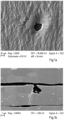
- Figure 1b shows an SEM image of a micro-pore-laden microsection of a foil package that was prepared using a cross section polisher (CSP).
- the middle foil shows an indentation of about 1 ⁇ m and a micro-pore channel. It is assumed that micro-pores are three-dimensional structures that create a connection from one side of the foil to the other side of the foil that is not always straight.
- the aluminum alloy foils according to the invention made from the aforementioned aluminum alloy types AA8xxx and AAlxxx with a thickness of a maximum of 12 ⁇ m, a maximum of 9 ⁇ m or less than 8 ⁇ m, in the material state H2x or O, on the other hand, have a maximum number of pores with a pore size of 1 ⁇ m to 200 ⁇ m of a maximum of 12 per dm 2 , a maximum of 8 or a maximum of 6 per dm 2. Pores with a size of 1 ⁇ m to 20 ⁇ m, which are not taken into account according to DIN EN 546-6, are therefore also taken into account.
- the aluminum alloy foils according to the invention have a particularly low maximum number of pores with a pore size of 1 ⁇ m to 200 ⁇ m and thus also the smallest pores starting with a pore size of 1 ⁇ m, improved barrier properties of the aluminum alloy foil can be provided.
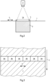
- FIG 2 A schematic sectional view of a device for measuring the maximum number of pores per dm 2 over the entire film width is shown.
- Figure 2 the aluminum alloy foil 1, a light source 2, for example an overhead projector, and a photo camera 3, which is to photograph the measuring surface 3A for evaluation.
- the device must be positioned in a darkened room so that no stray light affects the measurement.
- the residual illuminance in the darkened room is preferably less than 0.25 lux.
- the aluminum alloy foil 1 is fixed in the measuring area by a frame 5, which completely surrounds the measuring surface, so that the aluminum alloy foil 1 is positioned as evenly as possible in the measuring surface 3A.
- the light source 2 illuminates the aluminum alloy foil 1 through a transparent glass plate, which is Figure 2 is not shown. However, the extension of the light source 2 indicates that the illumination of the aluminum alloy foil 1 from below should be as homogeneous as possible.
- the distance of camera 3 depends on the size of the measuring area to be captured and the lens used. A lens with the shortest possible focal length should be selected so that the distance can be kept to a minimum in order to capture the measuring area with the best possible resolution.
- the light source 2 is completely darkened with the aluminum alloy foil and the frame 5, so that only light that has passed through pores in the aluminum alloy foil 1 within the measuring surface 3A can reach the camera.
- the aluminum alloy foil 1 is divided along the entire width 4 into preferably at least three or at least five measuring surfaces, so that the entire width of the foil is recorded in the measurement. Since the aluminum alloy foils are often made into so-called rolls to specific widths after the foil rolling and then annealed, the width 4 of the aluminum alloy foil 1 means the width of the foil roll or, without making up, the entire width of the foil coil.
- the division into different measuring surfaces 3A also enables the detection of locally occurring populations of pores with sizes from 1 ⁇ m to 20 ⁇ m. These pores are not taken into account in the known porosity measurement according to DIN EN 546-4.
- the following test setup was used for the films measured below:
- the light source was an overhead projector from Andreas + Kern with an optical halogen lamp 36 V and 400 W with a luminous flux of up to 6000 lumens.
- the film to be examined was placed on the projector and fixed using a metal frame of a defined size so that the film lay flat on the projector and was sealed at the sides.
- the camera used was a Sony Alpha 6000 with 6000 ⁇ 4000 pixels with a Minolta MD Rokkor 50 mm f1.4 lens.
- An aperture of 2 with an ISO value of 800 and an exposure time of 30 seconds were used for the images.
- the distance from the camera sensor to the film was 700 mm.
- the software was used for image analysis. Image Analyzer was used.
- the measuring areas 3A were, as Figure 4 shows, arranged side by side without gaps across the width 4 perpendicular to the longitudinal direction 7 of the aluminum alloy foil 1, so that the entire width of the aluminum alloy foil 1 is measured.
- the size of the measuring area was 183 mm ⁇ 276 mm and thus 5.0508 dm 2 .
- the number of pores with a size of 1 ⁇ m to 200 ⁇ m was then determined using software and standardized to 1 dm 2 by dividing the measured number of pores in the worst measuring area by the total area of the measuring area in dm 2. The result was rounded to a whole number. With this measuring method, the smallest pores that occur locally and have a size of less than 20 ⁇ m, in particular 5 ⁇ m to 1 ⁇ m, can be detected and counted.
- an aluminum alloy with an alloy composition according to Table 1 was cast into a rolling ingot.
- the aluminum alloy melt was treated with purge gases before and/or during the casting of the rolling ingot and filtered through a degasser and a deep-bed filter. As already explained, this filtration serves to prevent non-metallic impurities from the melt in the subsequent rolling ingot.
- the rolling ingot was then subjected to homogenization, which for the aluminum alloy in question was carried out in the temperature range of 420-600 °C for at least 5 hours in order to bring as many casting phases as possible back into solution.
- the rolling ingot was then hot rolled to a final hot rolling thickness of 2 mm to 4 mm and wound up into a hot strip with a final hot strip temperature of between 300 °C and 350 °C.
- the hot strip was cold rolled in several cold rolling passes to an intermediate thickness of, for example, 0.60 mm to a maximum of 0.80 mm.
- a recrystallization annealing was then carried out at a furnace air temperature of 450 °C to 550 °C for at least 5 hours.
- the aluminum strip recrystallized in this way was subjected to further cold rolling steps to a second intermediate thickness of between 11 ⁇ m and 20 ⁇ m. and doubled for foil rolling. After doubling, an intermediate annealing took place for half an hour at a furnace air temperature of 240 °C to 320 °C.
- the foil rolling of the doubled strip was then carried out.
- the coil was optionally made into rolls.
- the aluminum alloy foil had a final thickness of a maximum of 12 ⁇ m, a maximum of 9 ⁇ m or less than 8 ⁇ m. In the exemplary embodiment, the aluminum alloy foil had a thickness of 6.3 ⁇ m.
- the rolls were finally annealed at an oven air temperature of 200 °C to 245 °C for at least 150 hours with a cooling phase of at least 3 hours at an oven air temperature of 100 °C.
- the comparative example B was annealed at a temperature of 330 °C for 50 hours and then cooled to room temperature.
- Table 2 initially shows the mechanical properties of the aluminum alloy foil according to DIN EN 546-2 of the two variants A and B. It was found that the aluminum alloy A according to the invention surprisingly had similarly high elongation at break values A 100 mm measured diagonally to the rolling direction, as the variant B annealed at high temperature, despite higher yield strength values R p0.2 and tensile strength values R m . The comparison variant B, on the other hand, showed significantly lower yield strength values R p0.2 and lower tensile strength values R m .
- variant A according to the invention has a more homogeneous distribution of the oxide layer thickness across the roll width than variant B not according to the invention.
- the production variants A and B were now investigated with regard to the maximum number of pores per dm 2 according to the present invention.
- Further aluminium alloy foils were produced from alloy 1 and annealed using different processes.
- the measurements with the Figure 2 The device described showed that oven air temperatures of up to 245 °C for 150 hours with a cooling phase at 100 °C oven air temperature for 7 hours did not greatly influence the maximum number of pores per dm 2 .
- the maximum number of pores measured was 10 per dm 2 .
Landscapes
- Chemical & Material Sciences (AREA)
- Engineering & Computer Science (AREA)
- Mechanical Engineering (AREA)
- Materials Engineering (AREA)
- Metallurgy (AREA)
- Organic Chemistry (AREA)
- Physics & Mathematics (AREA)
- Thermal Sciences (AREA)
- Crystallography & Structural Chemistry (AREA)
- Metal Rolling (AREA)
- Laminated Bodies (AREA)
Claims (15)
- Feuille d'alliage d'aluminium ayant une épaisseur maximale de 12 µm, maximale de 9 µm ou inférieure à 8 µm, ladite feuille d'alliage d'aluminium comprenant un alliage d'aluminium AAlxxx ou AA8xxx dans l'état de matériau H2x ou O,
caractérisée en ce queladite feuille d'alliage d'aluminium aun nombrede pores ayant une grandeur de pores de 1 µm à 200 µm d'un maximum de 12 par dm2, d'un maximum de 8 par dm2 ou d'un maximum de 6 par dm2, le nombre de pores étant mesuré selon la description. - Feuille d'alliage d'aluminium selon la revendication 1,
caractérisée en ce quela feuille d'alliage d'aluminium présenteune épaisseur de couche d'oxyde de 3 à 6 nm mesurée le long de la largeur totale de la feuille d'alliage d'aluminium, l'épaisseur de la couche d'oxyde de la feuille d'alliage d'aluminium étant supérieure d'au maximum 30 % dans la zone excentrée de la feuille d'alliage d'aluminium qu'au centre de la feuille d'alliage d'aluminium. - Feuille d'alliage d'aluminium selon l'une des revendications 1 ou 2,
caractérisée en ce que
l'épaisseur de la couche d'oxyde est de 5 nm au maximum, tant sur la face mate que sur la face brillante de la feuille d'alliage d'aluminium. - Feuille d'alliage d'aluminium selon l'une quelconque des revendications 1 à 3,
caractérisée en ce que
la feuille d'alliage d'aluminium comprend un alliage d'aluminium ayant les composants d'alliage suivants, en % en poids :0,05 % ≤ Si ≤ 0,30 %,Fe : 0,7 ≤ Fe ≤ 1,3 %,Cu ≤ 0,05 %,Mn ≤ 0,05 %,Mg ≤ 0,05 %,Cr ≤ 0,05 %,Zn ≤ 0,10 %,Ti ≤0,025 %,le reste étant de l'Al et des impuretés inévitables, individuellement au maximum 0,05 % en poids, au total au maximum 0,15 % en poids. - Feuille d'alliage d'aluminium selon la revendication 4,
caractérisée en ce que
l'alliage de la feuille d'alliage d'aluminium présente au moins une des autres limitations des composants de l'alliage en % en poids :0,05 % ≤ Si ≤ 0,30 %,0,8 ≤ Fe ≤ 1,15 %,Cu ≤ 0,05 %,0,01 % ≤ Mn ≤ 0,04 %, de préférence 0,015 % ≤ Mn ≤ 0,035 %, de manière particulièrement préférée 0,018 % ≤ Mn ≤ 0,025 %,Mg ≤ 0,01 %, de préférence Mg ≤ 0,005 %, de manière particulièrement préféréeMg ≤ 0,0035 %,Cr ≤ 0,02 %,Zn ≤ 0,07 % et/ou0,005 % ≤ Ti ≤ 0,025 %. - Feuille d'alliage d'aluminium selon la revendication 4 ou 5,
caractérisée en ce que
la feuille d'alliage d'aluminium présente, à l'état de matériau O, une limite d'élasticité Rp0,2 selon DIN EN 546-2, mesurée transversalement, longitudinalement ou en diagonale par rapport au sens de laminage, d'au moins 55 MPa, de préférence d'au moins 58 MPa. - Feuille d'alliage d'aluminium selon l'une des revendications 3 ou 4,
caractérisée en ce que
la feuille d'alliage d'aluminium présente une résistance à la traction Rm selon la norme DIN EN 546-2, mesurée dans le sens transversal, longitudinal et/ou diagonal par rapport au sens de laminage, à l'état de matériau H2x ou O, d'au moins 80 MPa. - Feuille d'alliage d'aluminium selon l'une des revendications 3 à 5,
caractérisée en ce que
l'allongement à la rupture A100mm selon DIN EN 546-2 de la feuille d'alliage d'aluminium, mesuré en diagonale par rapport au sens de laminage, est d'au moins 6,2 %, de préférence d'au moins 6,5 %. - Procédé de fabrication d'une feuille d'alliage d'aluminium selon les
revendications 1 à 8,
ledit procédé comprenant les étapes suivantes :- préparation d'une bande d'alliage d'aluminium pour le laminage à froid par coulée d'une billette d'alliage d'aluminium à partir d'un alliage d'aluminium AAlxxx ou AA8xxx, dans laquelle l'alliage d'aluminium fondue est filtré avant et/ou pendant la coulée de la billette, homogénéisation de la barre de laminage coulée et laminage à chaud de la barre de laminage en une bande à chaud ou coulée continue d'une bande de coulée à partir d'une masse fondue d'un alliage d'aluminium filtré de type AA8xxx ou AA1xxx, suivie d'un laminage à chaud optionnel de la bande de coulée,- laminage à froid de la bande d'alliage d'aluminium à une première épaisseur intermédiaire,- recuit de recristallisation de la bande d'alliage d'aluminium laminée à froid à cette épaisseur intermédiaire,- laminage à froid de la bande d'alliage d'aluminium à une deuxième épaisseur intermédiaire,- doublage de la bande d'alliage d'aluminium et réalisation d'un recuit intermédiaire,- laminage de la feuille de la bande d'alliage d'aluminium doublée à l'épaisseur finale de la feuille doublée,- séparation et enroulement des couches à une épaisseur finale des différentes couches de 12, 9 µm au maximum ou moins de 8 µm, une confection de la feuille d'alliage d'aluminium en plusieurs rouleaux étant éventuellement effectuée, et- réalisation d'un recuit final de la bobine ou des rouleaux confectionnés pendant au moins 150 h à une température d'air de four de 200 à 245 °C avec une phase de refroidissement finale pendant au moins 3 h, de préférence au moins 7 h à une température d'air de four de 100 °C. - Procédé selon la revendication 9,
caractérisée en ce que
l'alliage d'aluminium comprend les éléments d'alliage suivants, en % en poids :0,05 % ≤ Si ≤ 0,30 %,0,7 ≤ Fe ≤ 1,3 %,Cu ≤ 0,05 %,Mn ≤ 0,05 %,Mg ≤ 0,05 %,Cr ≤ 0,05 %,Zn : ≤ 0,10 %,Ti : ≤ 0,025 %,le reste étant Al et des impuretés inévitables individuellement 0,05 % en poids, au total au maximum 0,15 % en poids, et- le recuit de recristallisation de la bande laminée à froid est effectué à une température d'air du four de 450 °C à 550 °C pendant au moins 5h et- le recuit intermédiaire après le doublage de la bande est effectué à une température d'air du four de 240 °C à 320 °C pendant 0,5h. - Procédé selon la revendication 10,
caractérisée en ce que
la feuille d'alliage d'aluminium présente au moins une des limitations suivantes des composants de l'alliage en % en poids :0,05 % ≤ Si ≤ 0,30 %,0,8 % ≤ Fe ≤ 1,15 %,Cu ≤ 0,05 %,0,01 % ≤ Mn ≤ 0,04 %, de préférence 0,015 % ≤ Mn ≤ 0,035 %, de manière particulièrement préférée 0,018 % ≤ Mn ≤ 0,025 %,Mg ≤ 0,01 %, de préférence Mg ≤ 0,005 %, de manière particulièrement préférée Mg ≤ 0,0035 %,Cr ≤ 0,02 %,Zn ≤ 0,07 % et/ou0,005 % ≤ Ti ≤ 0,025 %. - Procédé selon la revendication 9 ou 11,
caractérisée en ce quel'homogénéisation de la barre de laminageest effectuée à une température comprise entre 420 et 600 °C pendant au moins 7 heures - Procédé selon l'une quelconque des revendications 9 à 12,
caractérisée en ce que
la billette est laminée à chaud jusqu'à une épaisseur finale de laminage à chaud de 2 mm à 4 mm et la température finale de laminage à chaud est comprise entre 300°C et 350°C. - Procédé selon l'une quelconque des revendications 9 à 13,
caractérisée en ce que
le recuit final est effectué à une température comprise entre 200°C et 225°C pendant au moins 150h. - Utilisation d'une feuille d'alliage d'aluminium selon l'une des revendications 1 à 8, dans un matériau composite multicouche, en particulier des emballages avec exigence de barrière pour la feuille d'aluminium.
Applications Claiming Priority (2)
| Application Number | Priority Date | Filing Date | Title |
|---|---|---|---|
| EP20215692.3A EP4015658A1 (fr) | 2020-12-18 | 2020-12-18 | Feuille d'aluminium à propriétés de barrière améliorées |
| PCT/EP2021/086404 WO2022129475A1 (fr) | 2020-12-18 | 2021-12-17 | Feuille d'aluminium ayant des propriétés barrières améliorées |
Publications (3)
| Publication Number | Publication Date |
|---|---|
| EP4263884A1 EP4263884A1 (fr) | 2023-10-25 |
| EP4263884C0 EP4263884C0 (fr) | 2024-07-24 |
| EP4263884B1 true EP4263884B1 (fr) | 2024-07-24 |
Family
ID=73855921
Family Applications (2)
| Application Number | Title | Priority Date | Filing Date |
|---|---|---|---|
| EP20215692.3A Withdrawn EP4015658A1 (fr) | 2020-12-18 | 2020-12-18 | Feuille d'aluminium à propriétés de barrière améliorées |
| EP21839200.9A Active EP4263884B1 (fr) | 2020-12-18 | 2021-12-17 | Feuille d'aluminium à propriétés de barrière améliorées |
Family Applications Before (1)
| Application Number | Title | Priority Date | Filing Date |
|---|---|---|---|
| EP20215692.3A Withdrawn EP4015658A1 (fr) | 2020-12-18 | 2020-12-18 | Feuille d'aluminium à propriétés de barrière améliorées |
Country Status (8)
| Country | Link |
|---|---|
| US (1) | US12522894B2 (fr) |
| EP (2) | EP4015658A1 (fr) |
| CN (1) | CN116635548B (fr) |
| ES (1) | ES2991692T3 (fr) |
| HU (1) | HUE067874T2 (fr) |
| MX (1) | MX2023007070A (fr) |
| PL (1) | PL4263884T3 (fr) |
| WO (1) | WO2022129475A1 (fr) |
Families Citing this family (1)
| Publication number | Priority date | Publication date | Assignee | Title |
|---|---|---|---|---|
| CN116200618A (zh) * | 2023-01-13 | 2023-06-02 | 江苏华丰铝业有限公司 | 一种连续铸轧8079合金高强度高延伸率铝箔的制备方法 |
Family Cites Families (23)
| Publication number | Priority date | Publication date | Assignee | Title |
|---|---|---|---|---|
| CH654027A5 (de) * | 1983-08-23 | 1986-01-31 | Alusuisse | Verfahren zur herstellung feinkoerniger aluminiumwalzprodukte. |
| GB9405415D0 (en) * | 1994-03-18 | 1994-05-04 | Alcan Int Ltd | Aluminium foil |
| FR2813316B1 (fr) | 2000-08-29 | 2002-10-18 | Pechiney Rhenalu | Procede de fabrication de bandes tres minces en alliage aluminium-fer |
| FR2836154B1 (fr) * | 2002-02-15 | 2004-10-22 | Pechiney Rhenalu | Bandes minces en alliage aluminium-fer |
| CN1262680C (zh) * | 2002-08-30 | 2006-07-05 | 无锡银邦铝业有限公司 | 一种铝箔及其生产方法 |
| DE102006026575A1 (de) * | 2006-03-23 | 2007-09-27 | Hydro Aluminium Deutschland Gmbh | Funktionale Direktbeschichtung einer Aluminiumfolie |
| ES2407655T5 (es) * | 2007-11-30 | 2023-02-23 | Speira Gmbh | Banda de aluminio para soportes para planchas de impresión litográfica y su producción |
| CN101798646A (zh) * | 2010-04-22 | 2010-08-11 | 镇江鼎胜铝业股份有限公司 | 铝合金材料及双零铝箔的制造方法 |
| CN102329988A (zh) * | 2011-07-30 | 2012-01-25 | 湖南晟通科技集团有限公司 | 一种铝合金材料及用其制造双零箔的方法 |
| CN102329989B (zh) * | 2011-07-30 | 2016-05-25 | 晟通科技集团有限公司 | 一种铝合金材料及其制造双零铝箔的方法 |
| CN102329991A (zh) * | 2011-07-30 | 2012-01-25 | 湖南晟通科技集团有限公司 | 一种铝合金及用其制造双零箔的方法 |
| CN102329990B (zh) * | 2011-07-30 | 2016-01-20 | 湖南晟通科技集团有限公司 | 一种铝合金及其制造双零箔的方法 |
| CN102409199B (zh) * | 2011-11-15 | 2014-04-30 | 镇江鼎胜铝业股份有限公司 | 家用铝箔材料及家用铝箔的制造方法 |
| CN106011708B (zh) * | 2016-06-06 | 2017-12-05 | 中南大学 | 一种软包装用8021高性能铝箔的热处理工艺 |
| CN107312953B (zh) * | 2017-06-07 | 2018-11-20 | 烟台南山学院 | 一种超薄双零铝箔及其制备方法 |
| CN107475569B (zh) * | 2017-06-26 | 2019-05-24 | 烟台南山学院 | 一种双零铝箔及其生产方法 |
| JP6461249B2 (ja) * | 2017-07-06 | 2019-01-30 | 三菱アルミニウム株式会社 | アルミニウム合金箔およびアルミニウム合金箔の製造方法 |
| JP6461248B2 (ja) * | 2017-07-06 | 2019-01-30 | 三菱アルミニウム株式会社 | アルミニウム合金箔およびアルミニウム合金箔の製造方法 |
| JP2019065312A (ja) * | 2017-09-28 | 2019-04-25 | 株式会社Uacj | 集電体用アルミニウム合金箔及びその製造方法 |
| CN111601905A (zh) * | 2017-11-21 | 2020-08-28 | 海德鲁铝业钢材有限公司 | 用于制造锂离子蓄电池的高强度电池用电极箔 |
| CN108160738A (zh) * | 2017-12-22 | 2018-06-15 | 江苏鼎胜新能源材料股份有限公司 | 一种高延伸率药用铝箔的制备方法 |
| CN110157957A (zh) * | 2019-05-16 | 2019-08-23 | 昆山铝业有限公司 | 用于深冷绝热纸的铝箔及其制备方法 |
| US20230357899A1 (en) * | 2020-10-08 | 2023-11-09 | University Of North Texas | Heterogeneous microstructured aluminum alloys |
-
2020
- 2020-12-18 EP EP20215692.3A patent/EP4015658A1/fr not_active Withdrawn
-
2021
- 2021-12-17 ES ES21839200T patent/ES2991692T3/es active Active
- 2021-12-17 HU HUE21839200A patent/HUE067874T2/hu unknown
- 2021-12-17 PL PL21839200.9T patent/PL4263884T3/pl unknown
- 2021-12-17 CN CN202180085726.8A patent/CN116635548B/zh active Active
- 2021-12-17 WO PCT/EP2021/086404 patent/WO2022129475A1/fr not_active Ceased
- 2021-12-17 EP EP21839200.9A patent/EP4263884B1/fr active Active
- 2021-12-17 MX MX2023007070A patent/MX2023007070A/es unknown
-
2023
- 2023-06-13 US US18/333,992 patent/US12522894B2/en active Active
Also Published As
| Publication number | Publication date |
|---|---|
| HUE067874T2 (hu) | 2024-11-28 |
| CN116635548A (zh) | 2023-08-22 |
| CN116635548B (zh) | 2025-02-14 |
| EP4015658A1 (fr) | 2022-06-22 |
| EP4263884C0 (fr) | 2024-07-24 |
| PL4263884T3 (pl) | 2024-10-21 |
| ES2991692T3 (es) | 2024-12-04 |
| US20230323514A1 (en) | 2023-10-12 |
| US20250263816A2 (en) | 2025-08-21 |
| MX2023007070A (es) | 2023-07-06 |
| EP4263884A1 (fr) | 2023-10-25 |
| WO2022129475A1 (fr) | 2022-06-23 |
| US12522894B2 (en) | 2026-01-13 |
Similar Documents
| Publication | Publication Date | Title |
|---|---|---|
| EP2479296B1 (fr) | Procédé de fabrication d'un alliage d'aluminium sans particule primaire Si | |
| EP2959028B1 (fr) | Alliage en aluminium pour la fabrication de demi-produits ou de composants pour véhicules automobiles, procédé de fabrication d'une bande d'alliage en aluminium à partir de cet alliage en aluminium ainsi que la bande d'alliage en aluminium et utilisations de celui-ci | |
| DE69823112T2 (de) | Verfahren zur Herstellung von Blech aus einer Titanlegierung | |
| EP2220262B1 (fr) | Bande d'aluminium pour supports de plaques d'impression lithographiques et sa fabrication | |
| DE112006000023T5 (de) | Verfahren zur Herstellung eines Magnesiumlegierungsblechs sowie Magnesiumlegierungsblech | |
| DE69404008T2 (de) | Substrat aus Aluminium-Legierung für lithographische Druckplatten und Verfahren zur Herstellung | |
| DE69617265T2 (de) | Verfahren zur herstellung von dünnbändern aus aluminiumlegierungen mit hoher festigkeit und verformbarkeit | |
| DE29924474U1 (de) | Lithoband | |
| DE60125671T2 (de) | Verfahren und Vorrichtung zum Giessen einer Aluminium-Gleitlagerlegierung | |
| DE69828435T2 (de) | Verfahren zur herstellung von basiswerkstoff für folien aus aluminium-legierung | |
| DE3330814C2 (de) | Verfahren zur Herstellung von Aluminiumprodukten | |
| DE60213951T2 (de) | Herstellung von hochfesten folien aus aluminiumlegierungen mit guter wälzbarkeit | |
| DE60005610T2 (de) | Verbesserte Gusslegierungen | |
| EP3172354B1 (fr) | Cible de pulvérisation cathodique à base d'un alliage d'argent | |
| DE60213761T2 (de) | Herstellung von hochfesten folien aus aluminiumlegierungen | |
| EP3237647B1 (fr) | Alliage de brasage à base d'aluminium dépourvu de particules de si primaires et son procédé de production | |
| EP4263884A1 (fr) | Feuille d'aluminium ayant des propriétés barrières améliorées | |
| WO2007093605A1 (fr) | Alliage d'aluminium exempt de carbure d'aluminium | |
| DE2515774A1 (de) | Verfahren und vorrichtung zum verbessern der qualitaet, insbesondere der aeusseren beschaffenheit, von gegenstaenden, wie stangen oder walzdraht | |
| DE2925977C2 (de) | Verfahren zur Herstellung von halbharten Aluminiumblechen | |
| EP2495106B1 (fr) | Bande en aluminium pour support de plaques d'impression lithographique doté de revêtements à base d'eau | |
| JP3770825B2 (ja) | 電解コンデンサ用アルミニウム硬質箔 | |
| DE112023000540T9 (de) | Aluminiumlegierungshartlotblech | |
| DE19956692B4 (de) | Lithoband | |
| DE112023000545T5 (de) | Aluminiumlegierungshartlotblech |
Legal Events
| Date | Code | Title | Description |
|---|---|---|---|
| STAA | Information on the status of an ep patent application or granted ep patent |
Free format text: STATUS: UNKNOWN |
|
| STAA | Information on the status of an ep patent application or granted ep patent |
Free format text: STATUS: THE INTERNATIONAL PUBLICATION HAS BEEN MADE |
|
| PUAI | Public reference made under article 153(3) epc to a published international application that has entered the european phase |
Free format text: ORIGINAL CODE: 0009012 |
|
| STAA | Information on the status of an ep patent application or granted ep patent |
Free format text: STATUS: REQUEST FOR EXAMINATION WAS MADE |
|
| 17P | Request for examination filed |
Effective date: 20230614 |
|
| AK | Designated contracting states |
Kind code of ref document: A1 Designated state(s): AL AT BE BG CH CY CZ DE DK EE ES FI FR GB GR HR HU IE IS IT LI LT LU LV MC MK MT NL NO PL PT RO RS SE SI SK SM TR |
|
| GRAP | Despatch of communication of intention to grant a patent |
Free format text: ORIGINAL CODE: EPIDOSNIGR1 |
|
| STAA | Information on the status of an ep patent application or granted ep patent |
Free format text: STATUS: GRANT OF PATENT IS INTENDED |
|
| DAV | Request for validation of the european patent (deleted) | ||
| DAX | Request for extension of the european patent (deleted) | ||
| INTG | Intention to grant announced |
Effective date: 20240219 |
|
| GRAS | Grant fee paid |
Free format text: ORIGINAL CODE: EPIDOSNIGR3 |
|
| GRAA | (expected) grant |
Free format text: ORIGINAL CODE: 0009210 |
|
| STAA | Information on the status of an ep patent application or granted ep patent |
Free format text: STATUS: THE PATENT HAS BEEN GRANTED |
|
| AK | Designated contracting states |
Kind code of ref document: B1 Designated state(s): AL AT BE BG CH CY CZ DE DK EE ES FI FR GB GR HR HU IE IS IT LI LT LU LV MC MK MT NL NO PL PT RO RS SE SI SK SM TR |
|
| REG | Reference to a national code |
Ref country code: GB Ref legal event code: FG4D Free format text: NOT ENGLISH |
|
| REG | Reference to a national code |
Ref country code: CH Ref legal event code: EP |
|
| REG | Reference to a national code |
Ref country code: IE Ref legal event code: FG4D Free format text: LANGUAGE OF EP DOCUMENT: GERMAN Ref country code: DE Ref legal event code: R096 Ref document number: 502021004527 Country of ref document: DE |
|
| U01 | Request for unitary effect filed |
Effective date: 20240801 |
|
| U07 | Unitary effect registered |
Designated state(s): AT BE BG DE DK EE FI FR IT LT LU LV MT NL PT SE SI Effective date: 20240822 |
|
| REG | Reference to a national code |
Ref country code: GR Ref legal event code: EP Ref document number: 20240401871 Country of ref document: GR Effective date: 20241007 |
|
| REG | Reference to a national code |
Ref country code: HU Ref legal event code: AG4A Ref document number: E067874 Country of ref document: HU |
|
| REG | Reference to a national code |
Ref country code: ES Ref legal event code: FG2A Ref document number: 2991692 Country of ref document: ES Kind code of ref document: T3 Effective date: 20241204 |
|
| U20 | Renewal fee for the european patent with unitary effect paid |
Year of fee payment: 4 Effective date: 20241218 |
|
| PG25 | Lapsed in a contracting state [announced via postgrant information from national office to epo] |
Ref country code: IS Free format text: LAPSE BECAUSE OF FAILURE TO SUBMIT A TRANSLATION OF THE DESCRIPTION OR TO PAY THE FEE WITHIN THE PRESCRIBED TIME-LIMIT Effective date: 20241124 |
|
| PG25 | Lapsed in a contracting state [announced via postgrant information from national office to epo] |
Ref country code: HR Free format text: LAPSE BECAUSE OF FAILURE TO SUBMIT A TRANSLATION OF THE DESCRIPTION OR TO PAY THE FEE WITHIN THE PRESCRIBED TIME-LIMIT Effective date: 20240724 |
|
| PG25 | Lapsed in a contracting state [announced via postgrant information from national office to epo] |
Ref country code: RS Free format text: LAPSE BECAUSE OF FAILURE TO SUBMIT A TRANSLATION OF THE DESCRIPTION OR TO PAY THE FEE WITHIN THE PRESCRIBED TIME-LIMIT Effective date: 20241024 |
|
| PG25 | Lapsed in a contracting state [announced via postgrant information from national office to epo] |
Ref country code: RS Free format text: LAPSE BECAUSE OF FAILURE TO SUBMIT A TRANSLATION OF THE DESCRIPTION OR TO PAY THE FEE WITHIN THE PRESCRIBED TIME-LIMIT Effective date: 20241024 Ref country code: IS Free format text: LAPSE BECAUSE OF FAILURE TO SUBMIT A TRANSLATION OF THE DESCRIPTION OR TO PAY THE FEE WITHIN THE PRESCRIBED TIME-LIMIT Effective date: 20241124 Ref country code: HR Free format text: LAPSE BECAUSE OF FAILURE TO SUBMIT A TRANSLATION OF THE DESCRIPTION OR TO PAY THE FEE WITHIN THE PRESCRIBED TIME-LIMIT Effective date: 20240724 |
|
| PGFP | Annual fee paid to national office [announced via postgrant information from national office to epo] |
Ref country code: HU Payment date: 20241106 Year of fee payment: 4 |
|
| PG25 | Lapsed in a contracting state [announced via postgrant information from national office to epo] |
Ref country code: SM Free format text: LAPSE BECAUSE OF FAILURE TO SUBMIT A TRANSLATION OF THE DESCRIPTION OR TO PAY THE FEE WITHIN THE PRESCRIBED TIME-LIMIT Effective date: 20240724 Ref country code: RO Free format text: LAPSE BECAUSE OF FAILURE TO SUBMIT A TRANSLATION OF THE DESCRIPTION OR TO PAY THE FEE WITHIN THE PRESCRIBED TIME-LIMIT Effective date: 20240724 |
|
| PG25 | Lapsed in a contracting state [announced via postgrant information from national office to epo] |
Ref country code: SK Free format text: LAPSE BECAUSE OF FAILURE TO SUBMIT A TRANSLATION OF THE DESCRIPTION OR TO PAY THE FEE WITHIN THE PRESCRIBED TIME-LIMIT Effective date: 20240724 |
|
| PLBE | No opposition filed within time limit |
Free format text: ORIGINAL CODE: 0009261 |
|
| STAA | Information on the status of an ep patent application or granted ep patent |
Free format text: STATUS: NO OPPOSITION FILED WITHIN TIME LIMIT |
|
| 26N | No opposition filed |
Effective date: 20250425 |
|
| PG25 | Lapsed in a contracting state [announced via postgrant information from national office to epo] |
Ref country code: MC Free format text: LAPSE BECAUSE OF FAILURE TO SUBMIT A TRANSLATION OF THE DESCRIPTION OR TO PAY THE FEE WITHIN THE PRESCRIBED TIME-LIMIT Effective date: 20240724 |
|
| PG25 | Lapsed in a contracting state [announced via postgrant information from national office to epo] |
Ref country code: IE Free format text: LAPSE BECAUSE OF NON-PAYMENT OF DUE FEES Effective date: 20241217 |
|
| REG | Reference to a national code |
Ref country code: CH Ref legal event code: U11 Free format text: ST27 STATUS EVENT CODE: U-0-0-U10-U11 (AS PROVIDED BY THE NATIONAL OFFICE) Effective date: 20260101 |
|
| PGFP | Annual fee paid to national office [announced via postgrant information from national office to epo] |
Ref country code: GB Payment date: 20251218 Year of fee payment: 5 |
|
| PGFP | Annual fee paid to national office [announced via postgrant information from national office to epo] |
Ref country code: NO Payment date: 20251222 Year of fee payment: 5 |
|
| PGFP | Annual fee paid to national office [announced via postgrant information from national office to epo] |
Ref country code: TR Payment date: 20251209 Year of fee payment: 5 Ref country code: GR Payment date: 20251128 Year of fee payment: 5 |
|
| PGFP | Annual fee paid to national office [announced via postgrant information from national office to epo] |
Ref country code: CZ Payment date: 20251126 Year of fee payment: 5 |
|
| U20 | Renewal fee for the european patent with unitary effect paid |
Year of fee payment: 5 Effective date: 20251217 |
|
| PGFP | Annual fee paid to national office [announced via postgrant information from national office to epo] |
Ref country code: PL Payment date: 20251126 Year of fee payment: 5 |
|
| PGFP | Annual fee paid to national office [announced via postgrant information from national office to epo] |
Ref country code: ES Payment date: 20260127 Year of fee payment: 5 |
|
| PGFP | Annual fee paid to national office [announced via postgrant information from national office to epo] |
Ref country code: CH Payment date: 20260101 Year of fee payment: 5 |
|
| PG25 | Lapsed in a contracting state [announced via postgrant information from national office to epo] |
Ref country code: CY Free format text: LAPSE BECAUSE OF FAILURE TO SUBMIT A TRANSLATION OF THE DESCRIPTION OR TO PAY THE FEE WITHIN THE PRESCRIBED TIME-LIMIT Effective date: 20240724 |