EP4264030B1 - Flugzeugturbinentriebwerkanordnung mit einem halter für verbraucher - Google Patents
Flugzeugturbinentriebwerkanordnung mit einem halter für verbraucher Download PDFInfo
- Publication number
- EP4264030B1 EP4264030B1 EP21851830.6A EP21851830A EP4264030B1 EP 4264030 B1 EP4264030 B1 EP 4264030B1 EP 21851830 A EP21851830 A EP 21851830A EP 4264030 B1 EP4264030 B1 EP 4264030B1
- Authority
- EP
- European Patent Office
- Prior art keywords
- assembly
- turbine engine
- intermediate casing
- hub
- turbomachine
- Prior art date
- Legal status (The legal status is an assumption and is not a legal conclusion. Google has not performed a legal analysis and makes no representation as to the accuracy of the status listed.)
- Active
Links
Images


Classifications
-
- F—MECHANICAL ENGINEERING; LIGHTING; HEATING; WEAPONS; BLASTING
- F02—COMBUSTION ENGINES; HOT-GAS OR COMBUSTION-PRODUCT ENGINE PLANTS
- F02C—GAS-TURBINE PLANTS; AIR INTAKES FOR JET-PROPULSION PLANTS; CONTROLLING FUEL SUPPLY IN AIR-BREATHING JET-PROPULSION PLANTS
- F02C7/00—Features, components parts, details or accessories, not provided for in, or of interest apart form groups F02C1/00 - F02C6/00; Air intakes for jet-propulsion plants
- F02C7/36—Power transmission arrangements between the different shafts of the gas turbine plant, or between the gas-turbine plant and the power user
-
- F—MECHANICAL ENGINEERING; LIGHTING; HEATING; WEAPONS; BLASTING
- F02—COMBUSTION ENGINES; HOT-GAS OR COMBUSTION-PRODUCT ENGINE PLANTS
- F02C—GAS-TURBINE PLANTS; AIR INTAKES FOR JET-PROPULSION PLANTS; CONTROLLING FUEL SUPPLY IN AIR-BREATHING JET-PROPULSION PLANTS
- F02C3/00—Gas-turbine plants characterised by the use of combustion products as the working fluid
- F02C3/04—Gas-turbine plants characterised by the use of combustion products as the working fluid having a turbine driving a compressor
- F02C3/10—Gas-turbine plants characterised by the use of combustion products as the working fluid having a turbine driving a compressor with another turbine driving an output shaft but not driving the compressor
-
- F—MECHANICAL ENGINEERING; LIGHTING; HEATING; WEAPONS; BLASTING
- F02—COMBUSTION ENGINES; HOT-GAS OR COMBUSTION-PRODUCT ENGINE PLANTS
- F02C—GAS-TURBINE PLANTS; AIR INTAKES FOR JET-PROPULSION PLANTS; CONTROLLING FUEL SUPPLY IN AIR-BREATHING JET-PROPULSION PLANTS
- F02C7/00—Features, components parts, details or accessories, not provided for in, or of interest apart form groups F02C1/00 - F02C6/00; Air intakes for jet-propulsion plants
- F02C7/20—Mounting or supporting of plant; Accommodating heat expansion or creep
-
- F—MECHANICAL ENGINEERING; LIGHTING; HEATING; WEAPONS; BLASTING
- F02—COMBUSTION ENGINES; HOT-GAS OR COMBUSTION-PRODUCT ENGINE PLANTS
- F02C—GAS-TURBINE PLANTS; AIR INTAKES FOR JET-PROPULSION PLANTS; CONTROLLING FUEL SUPPLY IN AIR-BREATHING JET-PROPULSION PLANTS
- F02C7/00—Features, components parts, details or accessories, not provided for in, or of interest apart form groups F02C1/00 - F02C6/00; Air intakes for jet-propulsion plants
- F02C7/32—Arrangement, mounting, or driving, of auxiliaries
-
- F—MECHANICAL ENGINEERING; LIGHTING; HEATING; WEAPONS; BLASTING
- F05—INDEXING SCHEMES RELATING TO ENGINES OR PUMPS IN VARIOUS SUBCLASSES OF CLASSES F01-F04
- F05D—INDEXING SCHEME FOR ASPECTS RELATING TO NON-POSITIVE-DISPLACEMENT MACHINES OR ENGINES, GAS-TURBINES OR JET-PROPULSION PLANTS
- F05D2240/00—Components
- F05D2240/90—Mounting on supporting structures or systems
-
- Y—GENERAL TAGGING OF NEW TECHNOLOGICAL DEVELOPMENTS; GENERAL TAGGING OF CROSS-SECTIONAL TECHNOLOGIES SPANNING OVER SEVERAL SECTIONS OF THE IPC; TECHNICAL SUBJECTS COVERED BY FORMER USPC CROSS-REFERENCE ART COLLECTIONS [XRACs] AND DIGESTS
- Y02—TECHNOLOGIES OR APPLICATIONS FOR MITIGATION OR ADAPTATION AGAINST CLIMATE CHANGE
- Y02T—CLIMATE CHANGE MITIGATION TECHNOLOGIES RELATED TO TRANSPORTATION
- Y02T50/00—Aeronautics or air transport
- Y02T50/60—Efficient propulsion technologies, e.g. for aircraft
Definitions
- This disclosure relates to the general field of turbomachines, in particular aeronautical turbomachines.
- This disclosure relates to the mounting of an equipment support in such a turbomachine, and more particularly to an assembly for an aircraft turbomachine comprising an equipment support.
- a turbomachine used for example for the propulsion of an aircraft such as an airplane or a helicopter
- the equipment and accessories such as pumps for the production of hydraulic energy, fuel supply and lubrication, electric generators for the production of electric power, etc.
- an equipment support commonly called an accessory box or relay, or AGB for "Accessory Gear Box”.
- Such a support generally carries one or more gear trains which are driven in rotation by a power draw on a shaft of the turbomachine and on which the various accessories are coupled.
- the equipment support may be provided around a compressor of the turbomachine. In these circumstances, it is then natural to fix at least partially the equipment support on the compressor casing. However, this can lead to an ovalization phenomenon of the casing, which affects the performance of the compressor. Faced with this problem, the patent application FR 2 952 672 of the Applicant proposes to suspend the equipment support from the beam (also called a pylon) located above the compressor casing and by which the turbojet engine is attached to the wing of an aircraft, in a configuration where the suspension of the turbojet engine from this beam is carried out at the level of an intermediate casing hub of the engine.
- the beam also called a pylon
- the present disclosure relates to an assembly for an aircraft turbomachine, comprising an intermediate casing hub, an equipment support, and a transfer case comprising a power transmission shaft configured to transmit mechanical power, taken from a drive shaft of the turbomachine, to at least one piece of equipment mounted on the equipment support, in which the transfer case comprises a structural element surrounding the power transmission shaft and rigidly fixing the equipment support to the intermediate casing hub.
- the axis of the turbomachine is an axis of rotation of a rotor of the turbomachine, for example a compressor rotor.
- the axial direction corresponds to the direction of the axis of the turbomachine and a radial direction is a direction perpendicular to this axis and intersecting this axis.
- an axial plane is a plane containing the axis of the turbomachine and a radial plane is a plane perpendicular to this axis.
- a circumference is understood as a circle belonging to a radial plane and whose center belongs to the axis of the turbomachine.
- a tangential or circumferential direction is a direction tangent to a circumference; it is perpendicular to the axis of the turbomachine but does not pass through the axis.
- interior and exterior are used in reference to a radial direction so that the interior part of an element is, in a radial direction, closer to the axis of the turbomachine than the exterior part of the same element.
- upstream and downstream are used in reference to the overall direction of flow in a turbomachine, namely from the compressor to the turbine.
- the intermediate casing is located upstream of the compressor casing, if necessary upstream of the high-pressure compressor casing (and optionally downstream of the low-pressure compressor casing) when the turbomachine comprises several compressors.
- the turbomachine comprises a fan
- the intermediate casing is located downstream of the fan retention casing, which is arranged annularly around the fan.
- the intermediate casing hub designates a radially inner part of the intermediate casing.
- the intermediate casing hub can designate the part of the intermediate casing that separates the primary flow from the secondary flow.
- the role of the intermediate casing hub is to allow for structural continuity between the primary flow and the secondary flow, to transmit forces to the upstream suspensions of the turbomachine.
- the intermediate casing hub can be used to fix the yokes of the thrust recovery connecting rods, the discharge outlets of the low-pressure air compressor and various equipment such as cylinders, probes, etc.
- the transfer case houses at least in part the power transmission shaft, also called transfer shaft, configured to transmit to the equipment support mechanical power taken from a drive shaft, for example a high-pressure or low-pressure body shaft of the turbomachine.
- the kinematic connection between the power transmission shaft and the drive shaft can be made via a gear and by means of a shaft, in particular a radial shaft.
- the mechanical power can be transmitted to at least one piece of equipment mounted on the equipment support in order to rotate a moving part of the equipment, generally by means of gears provided between the power transmission shaft and the equipment.
- the transfer case therefore extends between the intermediate casing hub, which partially houses said drive shaft and where appropriate the radial shaft, and the equipment support.
- the aircraft turbomachine assembly cleverly uses the transfer case by including a structural element in order to rigidly fix the equipment support to the intermediate casing hub, which makes it possible to dispense with the need for fixing the support. of equipment both on a compressor casing and on a beam attached to an aircraft wing.
- a structural element is an element configured to perform a role of maintaining the structure and absorbing forces.
- the structural element allows the equipment support to be fixed independently to the intermediate casing hub, even if, as will be seen later, other elements may intervene to absorb the forces according to certain degrees of freedom.
- the structural element is such that without this element, the equipment support would not be rigidly fixed to the intermediate casing hub.
- the transfer case includes a structural element rigidly fixing the equipment support to the intermediate casing hub
- the equipment support adapts to any type of aircraft turbomachine without requiring the addition of a beam
- the equipment support fixings are further simplified, which frees up design freedom for other aspects of the turbomachine.
- the equipment support is formed by a housing that has an upstream face located downstream of the intermediate housing hub, and the structural element is rigidly attached to said upstream face.
- the attachment via the structural element is therefore simple and robust.
- the assembly further comprises two arms connecting the equipment support to the intermediate housing hub. These arms make it possible to mainly absorb the moments along three orthogonal axes, these moments being able to become significant when the equipment support is sized to carry at least three pieces of equipment, while the structural element can be configured to mainly absorb the forces along said three axes. Thus, the six degrees of freedom of the equipment support are well absorbed.
- the arms are provided on either side of the structural element. This distributes the load-bearing between the two arms.
- the assembly has no other attachment between the equipment support and the intermediate housing hub than the structural member and said two arms.
- the number of attachments of the equipment support to the intermediate housing hub is therefore minimized, which provides even more design freedom for other aspects of the turbomachine.
- At least one of the two arms is configured to take up the forces in the axis of the arms (in tension and/or compression).
- At least one of the two arms is fixed to the intermediate housing hub and/or to the equipment support in an articulated manner so as to absorb the forces only in the axis of the arms (in tension and/or compression).
- An articulation may comprise two parts mechanically in motion relative to each other, in which case the arm concerned may be a connecting rod, for example a ball-jointed connecting rod, and/or comprise an elastically deformable part so as to allow a certain movement of the arm, which may then be a simple beam, relative to the intermediate housing hub and/or to the equipment support.
- the structural element and the two hingedly fixed arms are an example of the aforementioned isostatic fixation, however other examples are envisaged. For example, it is possible to use more arms if these have sufficient degrees of freedom so as not to make the connection hyperstatic.
- the structural element is formed by a sleeve of the transfer case.
- the sleeve can surround the power transmission shaft at least over a portion of the length of said shaft.
- the sleeve can be a tubular or even cylindrical element of any cross-section, optionally circular.
- the sleeve can be an outer housing of the transfer case, configured to house the remainder of the transfer case.
- the power transmission shaft extends substantially perpendicular to the upstream face of the equipment support.
- the upstream face of the equipment carrier is downstream of the intermediate housing hub.
- the upstream face of the equipment carrier may be a distance downstream of the intermediate housing hub, in order to free up space for mounting equipment on the upstream face of the equipment carrier. In this way, the equipment can be better distributed on the equipment support.
- the upstream face can be transverse to the axis of the turbomachine.
- the aircraft turbomachine assembly comprises at least one piece of equipment mounted on the upstream face of the equipment support. Said equipment is, of course, distinct from the transfer case.
- Said equipment may have an axial dimension less than the distance (in particular axial) between said upstream face and a downstream annular flange of the intermediate casing hub.
- the equipment support can be mounted so that it is located, in the turbomachine, axially at the level of a compressor casing. In this case, the accessibility and maintenance of the equipment support are unchanged for operators, despite the change of attachment.
- the attachment of the equipment support to the intermediate housing hub is isostatic. Consequently, the dimensioning of the assembly is facilitated and the attachment does not require any adjustment during its assembly.
- the aircraft turbomachine comprises a compressor casing, the compressor casing having a relatively small diameter compared to the diameter of the fan or the propeller.
- the diameter of the compressor casing may be, at its attachment to the hub of the intermediate casing, equal to the inner diameter of the intermediate casing hub.
- the equipment support is attached to the intermediate housing hub so as to be, in the use position, substantially below an axis of the intermediate housing hub.
- the position of use is a position in which the turbomachine assembly is integrated into a turbomachine itself assembled to an aircraft. In this position, at least 50% of the volume of the support equipment support is located below the centerline of the intermediate housing hub.
- Such situations occur when the equipment support is said to be "mounted at six o'clock" (6 o'clock), for example, by referring to an imaginary clock whose 12 o'clock-6 o'clock axis is aligned with the vertical, 12 o'clock being at the top and 6 o'clock at the bottom.
- the equipment support may also be mounted at 5 o'clock, 7 o'clock, etc.
- the reference point may be a center of gravity of the equipment support, possibly provided with its equipment and accessories.
- the equipment support extends along a ring portion.
- the equipment support may therefore be provided as close as possible to the main axis, around the engine compartment, so as to maintain a compact turbomachine.
- the ring portion may be an arc of a circle, centered or not on the axis of the turbomachine.
- the intermediate housing hub includes a downstream annular flange to which the structural element is attached
- the transfer case includes an angle gear disposed in the intermediate housing hub upstream of the downstream annular flange, said angle gear connecting the power transmission shaft to the engine shaft of the turbomachine via a radial shaft of the turbomachine.
- the angle gear may allow the transmission of mechanical power between the radial shaft and the power transmission shaft.
- the downstream annular flange may be the same as that mentioned previously.
- the ring portion covers an angular sector less than 180°.
- the present disclosure also relates to an aircraft turbomachine comprising an assembly according to any of the embodiments previously defined.
- the aircraft may be, in particular, an airplane or a helicopter.
- the turbomachine may be a turbojet, a turboprop, an auxiliary power unit (commonly called APU for "Auxi / iary Power Unit "), etc.
- the aircraft turbomachine comprises, downstream of the intermediate casing, a compressor casing and a combustion chamber casing, and the assembly described above is devoid of attachment between the equipment support and the compressor casing, and devoid of attachment between the equipment support and the combustion chamber housing. The performance of the turbomachine is therefore preserved.
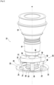
- turbomachine 10 there figure 1 represents in section, in a simplified manner, a turbomachine 10 according to one embodiment.
- the figures 2 And 3 represent a portion of the turbomachine 10 in perspective, in bottom and side view respectively.
- the turbomachine 10 is in this case a twin-spool, twin-flow turbojet, but the present disclosure extends to other types of turbomachines, as previously mentioned.
- the turbomachine 10, or a turbomachine of another type may be mounted under the wing of an aircraft, on the wing or at the rear of the fuselage of the aircraft.
- the turbomachine 10 generally extends along a main axis X forming the axis of rotation of at least part of its rotors.
- the turbomachine 10 may comprise, from upstream to downstream, a fan retention casing 12, an intermediate casing 14, a compressor casing 60, a combustion chamber casing 16 and a turbine casing 18. Where appropriate, some of these casings may be divided into several sections; for example, the turbine casing 18 may comprise a high-pressure turbine casing, an inter-turbine casing and a low-pressure turbine casing.
- the different housings can be annular, or even axisymmetric, and centered on the X axis.
- the intermediate casing 14 includes an outer shroud 15 and an intermediate casing hub 30.
- the intermediate casing hub 30 may be connected to the outer shroud 15 by straighteners 15a (commonly referred to as OGVs for “Out / and Guide Vanes ”) for straightening the secondary flow from the fan, as well as by structural arms 15b.
- straighteners 15a commonly referred to as OGVs for “Out / and Guide Vanes ”
- the intermediate casing hub 30 can form a separation between a so-called primary vein, configured to guide the primary flow passing through the core of the turbomachine and intended to participate in the combustion and the driving of at least one turbine, and a so-called secondary vein, configured to guide the secondary flow passing through the OGVs 15a to generate most of the thrust of the turbomachine 10.
- the intermediate casing hub 30 comprises a downstream annular flange 32 extending radially inwards from a downstream part of a frustoconical portion 34.
- the frustoconical portion 34 may be, at least in its downstream part, substantially concentric with the external ferrule 15 and, in the particular case, axisymmetric around the main axis X.
- the intermediate casing hub 30 may further comprise, here in the downstream flange 32, one or more openings 36 for the passage of discharge outlets of the compressor, in particular low-pressure compressor. These outlets are commonly called VBV outlets (for “Variable Bleed Valve ”). In this case, the openings 36 are oval. The openings 36 may be arranged next to each other along a circumference.
- the intermediate housing hub 30 may be made of metal, for example titanium, steel, aluminum, or an alloy comprising one or more of these metals.
- the intermediate housing hub 30 may also comprise an upstream flange 31.
- the upstream flange 31, annular extends radially inward from an upstream portion of the frustoconical portion 34.
- Between the upstream flange 31 and the downstream flange 32 are one or more hollow structures, extending for example in the continuity of arms which cross the primary vein, and optionally in the continuity of the structural arms 15b, as illustrated. These hollow structures allow the passage of services, such as lubrication circuits, speed measuring means, etc., but also of a radial shaft 38 whose role will be described later.
- an assembly for an aircraft turbomachine 20 comprises the aforementioned intermediate casing hub 30, but also an equipment support 40.
- THE figures 2 And 3 show that the equipment support 40 extends along a ring portion, here around the main axis X.
- the ring portion covers an angular sector less than 180°, in this case less than 120°.
- the equipment support 40 may be formed by a housing which has an upstream face 42, facing the intermediate casing hub 30, and an opposite face called the downstream face 44, facing downstream of the turbomachine, for example towards the turbine casing 18.
- the upstream face 42 and/or the downstream face 44 may be substantially flat, and/or extend transversely to the main axis X, as illustrated.
- the equipment support 40 may contain one or more gear trains (not shown) which are driven in rotation by a power draw on a drive shaft 17 (for example the high-pressure body shaft) of the turbomachine 10.
- a drive shaft 17 for example the high-pressure body shaft
- One or more pieces of equipment may be mounted on the equipment support 40 and may each have a drive shaft which is coupled to one of the gears of the equipment support 40.
- These drive shafts may extend in a direction substantially parallel to the main axis X.
- an electric generator for supplying electric power to the aircraft
- an alternator for supplying electric current to electrical equipment of the turbomachine
- a starter for starting the turbomachine
- a hydraulic pump for supplying hydraulic power to the aircraft
- a fuel pump for supplying hydraulic power to the aircraft
- a fuel pump for supplying hydraulic power to the aircraft
- a lubrication pump for supplying hydraulic power to the aircraft
- other equipment can be mounted on the equipment support 40.
- a piece of equipment 46 is shown, which is here mounted on the upstream face 42 of the equipment support 40.
- such equipment could also be mounted on the downstream face 44.
- the aircraft turbomachine assembly 20 comprises a transfer case 50 comprising a power transmission shaft 54 configured to transmit mechanical power, taken from a drive shaft 17 of the turbomachine, to at least one piece of equipment mounted on the equipment support, where appropriate via the gears mentioned above.
- the power transmission shaft 54 can take mechanical power from the engine shaft 17 by an intermediate shaft called a radial shaft 38, due to its positioning generally in a radial direction of the turbomachine 10.
- the transfer case 50 can comprise a bevel gear 56 forming a kinematic connection between the radial shaft 38 and the power transmission shaft 54.
- the bevel gear 56 can comprise a bevel gear coupling.
- the angle gear 56 can be located between the upstream flange 31 and the downstream flange 32 of the intermediate housing hub 30.
- the transfer case 50 comprises a structural element 52 rigidly fixing the equipment support 40 on the intermediate housing hub 30.
- the structural element 52 is formed by a sheath of the transfer case 50 (hereinafter also referred to as “sleeve 52”), said sheath 52 surrounding the power transmission shaft 54, as shown in the figures 2 And 3 .
- the sleeve 52 of the transfer case 50 is reinforced so as to be capable of supporting the weight of the equipment support 40 and the equipment 46 which it carries, and of keeping the equipment support 40 rigidly fixed to the intermediate housing hub 30.
- the sheath 52 is formed mainly by a wall which can be cylindrical, with a circular, elliptical, ellipsoidal, square, rectangular, polygonal or other section. If necessary, the sheath 52 can comprise longitudinal and/or circumferential reinforcements to give it the desired stiffness. The reinforcements can be provided on the inside or, preferably, on the outside of the wall of the sheath 52.
- the sheath can be metallic, for example made of steel, titanium, aluminum or alloys comprising at least one of these metals, or else made of a metal matrix composite or an organic matrix composite.
- the sheath 52 may be attached to a circumferentially central portion of the equipment support 40, or more generally to a portion such as that the weight of the equipment support 40 and the equipment 46 on either side of this part are balanced.
- the sheath 52 may be connected to the equipment support by bolting, V-Band type collar or any other method of attachment conceivable by those skilled in the art, preferably removable, which is sufficiently robust to allow the rigid attachment of the equipment support 40 to the intermediate casing hub 30.
- the transfer case 50 may be mounted against the upstream face 42 of the equipment support. More particularly, the structural element 52, here the sheath, may be fixed to the upstream face 42 of the equipment support 40, for example via a bolted flange.
- the equipment support 40 although fixed to the intermediate casing hub 30, can be positioned downstream of the intermediate casing hub 30.
- the equipment support 40 can be positioned axially at the compressor casing 60, more particularly at the high-pressure compressor casing, without however being fixed to this compressor casing 60.
- ovalization phenomena are avoided, a fortiori when the compressor casing is small compared to the size of the fan or the propeller.
- the aircraft turbomachine assembly 20 may comprise at least one arm 70, or even at least two arms 70, in this case exactly two arms 70. Unless otherwise stated, one of the arms 70 will be described below, the other being able to be identical or have other characteristics, in particular among those mentioned.
- the arm 70 connects the equipment support 40 to the intermediate casing hub 30, in order to ensure a recovery of forces, for example axial forces, for example in traction.
- the two arms 70 are provided on either side of the sheath 52, so as to limit the oscillation of the equipment support 40 around the fixing zone of the sheath 52 on the equipment support 40.
- the arm 70 is attached to the equipment support 40 by a first connection 72 and to the intermediate housing hub 30 by a second connection 74.
- One and/or the other of the first connection 72 and the second connection 74 can be articulated, so that the forces are taken up only in the axis of the arms (in traction and/or compression).
- the first link 72 may be a ball joint.
- the second connection 74 may comprise a flexible pad, for example comprising a succession of metal layers and layers of pre-stressed elastomer.
- connections may be interchanged, or made identical to each other, or other connections may be used, for example bolted connections, in particular associated with means for adjusting the mounting of the arms to compensate for the hyperstatic nature of the connection.
- connection 72 can be provided on a peripheral surface of the equipment support 40, or more generally on a surface distinct from the upstream face 42 and the downstream face 44, which leaves said faces available for mounting equipment.
- the arm 70 may be a beam or a connecting rod, typically metallic or composite.
- the section of such a beam or connecting rod may be sized by a person skilled in the art, for example with an H-shaped section or a hollow section, in particular of circular, ellipsoidal, square, rectangular or polygonal shape.
- the aircraft turbomachine assembly 20 has no other attachment between the equipment support 40 and the intermediate casing hub 30 than the structural element 52, namely the sheath, and the two arms 70 previously described. Thanks to such an assembly, the attachment of the equipment support 40 to the intermediate casing hub 30 is isostatic. However, other isostatic assemblies can be envisaged.
- connections 74 can be provided between successive openings 36, so that the arms 70 do not obstruct the discharge outlets of the compressor.
- FIG 3 which shows the turbomachine 10 in the operating position, illustrates that the equipment support 40 is fixed to the intermediate casing hub 30 so as to be located mainly below the main axis X of the intermediate casing hub 30.
- the equipment support 40 is mounted at 6 o'clock, in which it is suspended from the intermediate casing hub 30.
- This position which facilitates under-wing maintenance and the recovery of fluids during operation and when the engine is stopped, and minimizes the risk of fire because any leaks are evacuated by gravity, if necessary via the nacelle, makes it all the more advantageous not to fix the equipment support 40 on the compressor casing 60.
Landscapes
- Engineering & Computer Science (AREA)
- Chemical & Material Sciences (AREA)
- Combustion & Propulsion (AREA)
- Mechanical Engineering (AREA)
- General Engineering & Computer Science (AREA)
- Structures Of Non-Positive Displacement Pumps (AREA)
- General Details Of Gearings (AREA)
Claims (12)
- Flugzeugturbinentriebwerksanordnung (20), umfassend eine Zwischengehäusenabe (30), einen Halter für Ausrüstungen (40) und ein Verteilergetriebe (50), umfassend eine Kraftübertragungswelle (54), die konfiguriert ist, um die mechanische Kraft, die in der Verwendungsposition von einer Motorwelle (17) des Turbinentriebwerks abgezweigt wurde, auf mindestens eine Ausrüstung (46) zu übertragen, die in der Verwendungsposition auf den Halter für Ausrüstungen (40) montiert wurde, wobei das Verteilergetriebe (50) ein strukturelles Element (52) umfasst, das die Kraftübertragungswelle (54) umgibt und den Halter für Ausrüstungen (40) starr an die Zwischengehäusenabe (30) fixiert, wobei die Anordnung dadurch gekennzeichnet ist, dass sie außerdem zwei Arme (70) umfasst, die den Halter für Ausrüstungen (40) mit der Zwischengehäusenabe (30) verbinden, wobei die Arme (70) auf beiden Seiten des strukturellen Elements (52) vorgesehen sind.
- Flugzeugturbinentriebwerksanordnung nach Anspruch 1, wobei der Halter für Ausrüstungen (40) durch ein Gehäuse gebildet ist, das eine vorgelagerte Seite (42) darstellt, die sich nachgelagert von der Zwischengehäusenabe (30) befindet, und wobei das strukturelle Element (52) an der vorgelagerten Seite (42) starr fixiert ist.
- Flugzeugturbinenriebwerksanordnung nach Anspruch 1 oder 2, wobei die Anordnung keine andere Fixierung zwischen dem Halter für Ausrüstungen (40) und der Zwischengehäusenabe (30) aufweist als das strukturelle Element (52) und die zwei Arme (70).
- Flugzeugturbinentriebwerksanordnung nach einem der Ansprüche 1 bis 3, wobei mindestens einer der zwei Arme (70) an die Zwischengehäusenabe (30) und/oder den Halter für Ausrüstungen (40) auf gelenkige Weise fixiert ist, um nur die Zugkräfte wieder aufzunehmen.
- Flugzeugturbinentriebwerksanordnung nach einem der Ansprüche 1 bis 4, wobei das strukturelle Element (52) von einer Hülle des Verteilergetriebes (50) gebildet ist.
- Flugzeugturbinentriebwerksanordnung nach einem der Ansprüche 1 bis 5, wobei sich die Kraftübertragungswelle (54) im Wesentlichen senkrecht zur vorgelagerten Seite (42) des Halters für Ausrüstungen (40) erstreckt.
- Flugzeugturbinentriebwerksanordnung nach einem der Ansprüche 1 bis 6, umfassend mindestens eine Ausrüstung (46), die auf der vorgelagerten Seite (42) des Halters für Ausrüstungen (40) montiert ist, wobei die Ausrüstung (46) eine axiale Abmessung aufweist, die geringer als der Abstand zwischen der vorgelagerten Seite (42) und einem ringförmigen nachgelagerten Flansch (32) der Zwischengehäusenabe (30) ist.
- Flugzeugturbinentriebwerksanordnung nach einem der Ansprüche 1 bis 7, wobei die Fixierung des Halters für Ausrüstungen (40) an die Zwischengehäusenabe (30) isostatisch ist.
- Flugzeugturbinenriebwerksanordnung nach einem der Ansprüche 1 bis 8, wobei die Zwischengehäusenabe (30) einen ringförmigen nachgelagerten Flansch (32) umfasst, an den das strukturelle Element (52) fixiert ist, und das Verteilergetriebe (50) eine Eckumlenkung (56) umfasst, die in der Zwischengehäusenabe (30) vorgelagert von dem nachgelagerten ringförmigen Flansch (32) angeordnet ist, wobei die Eckumlenkung (56) die Kraftübertragungswelle (54) mit der Motorwelle des Turbinentriebwerks mit Hilfe einer radialen Welle (38) des Turbinentriebwerks verbindet.
- Flugzeugturbinentriebwerksanordnung nach einem der Ansprüche 1 bis 9, wobei der Halter für Ausrüstungen (40) derart an die Zwischengehäusenabe (30) fixiert ist, dass er sich in der Verwendungsposition zum Großteil unter einer Achse (X) der Zwischengehäusenabe (30) befindet.
- Flugzeugturbinentriebwerk (10), umfassend eine Anordnung (20) nach einem der Ansprüche 1 bis 10.
- Flugzeugturbinentriebwerk (10) nach Anspruch 11, umfassend nachgelagert von der Zwischengehäusenabe (14) ein Kompressorgehäuse (60) und ein Brennkammergehäuse (16), und wobei die Anordnung keine Fixierung zwischen dem Halter für Ausrüstungen (40) und dem Kompressorgehäuse (60) sowie dem Brennkammergehäuse (16) aufweist.
Applications Claiming Priority (2)
| Application Number | Priority Date | Filing Date | Title |
|---|---|---|---|
| FR2013272A FR3117530B1 (fr) | 2020-12-15 | 2020-12-15 | Ensemble pour turbomachine d’aéronef comprenant un support d’équipements |
| PCT/FR2021/052341 WO2022129788A1 (fr) | 2020-12-15 | 2021-12-15 | Ensemble pour turbomachine d'aéronef comprenant un support d'équipements |
Publications (2)
| Publication Number | Publication Date |
|---|---|
| EP4264030A1 EP4264030A1 (de) | 2023-10-25 |
| EP4264030B1 true EP4264030B1 (de) | 2024-11-27 |
Family
ID=74592214
Family Applications (1)
| Application Number | Title | Priority Date | Filing Date |
|---|---|---|---|
| EP21851830.6A Active EP4264030B1 (de) | 2020-12-15 | 2021-12-15 | Flugzeugturbinentriebwerkanordnung mit einem halter für verbraucher |
Country Status (5)
| Country | Link |
|---|---|
| US (1) | US20240052788A1 (de) |
| EP (1) | EP4264030B1 (de) |
| CN (1) | CN116635618A (de) |
| FR (1) | FR3117530B1 (de) |
| WO (1) | WO2022129788A1 (de) |
Families Citing this family (1)
| Publication number | Priority date | Publication date | Assignee | Title |
|---|---|---|---|---|
| FR3148621B1 (fr) | 2023-05-11 | 2025-04-25 | Safran Trans Systems | Suspension de boîtier auxiliaire |
Family Cites Families (27)
| Publication number | Priority date | Publication date | Assignee | Title |
|---|---|---|---|---|
| FR2866068B1 (fr) * | 2004-02-06 | 2006-07-07 | Snecma Moteurs | Turboreacteur a soufflante solidaire d'un arbre d'entrainement supporte par un premier et un deuxieme paliers |
| US7500365B2 (en) * | 2005-05-05 | 2009-03-10 | United Technologies Corporation | Accessory gearbox |
| US8040007B2 (en) * | 2008-07-28 | 2011-10-18 | Direct Drive Systems, Inc. | Rotor for electric machine having a sleeve with segmented layers |
| FR2946091A1 (fr) * | 2009-10-16 | 2010-12-03 | Snecma | Turbomachine d'aeronef comprenant un generateur electrique de puissance agence de facon inclinee dans le compartiment inter-veine |
| FR2952672B1 (fr) | 2009-11-17 | 2011-12-09 | Snecma | Montage d'un boitier d'accessoires sur un carter intermediaire pour compartiment de soufflante de turboreacteur |
| WO2012137844A1 (ja) * | 2011-04-07 | 2012-10-11 | 川崎重工業株式会社 | 航空機用エンジン |
| GB201121971D0 (en) * | 2011-12-21 | 2012-02-01 | Rolls Royce Deutschland & Co Kg | Accessory mounting for a gas turbine |
| US9016068B2 (en) * | 2012-07-13 | 2015-04-28 | United Technologies Corporation | Mid-turbine frame with oil system mounts |
| US9500133B2 (en) * | 2012-12-23 | 2016-11-22 | United Technologies Corporation | Mount with an axial upstream linkage for connecting a gearbox to a turbine engine case |
| GB201310810D0 (en) * | 2013-06-18 | 2013-07-31 | Rolls Royce Deutschland & Co Kg | An accessory mounting for a gas turbine engine |
| FR3007458B1 (fr) * | 2013-06-21 | 2017-11-10 | Snecma | Carter intermediaire ameliore de turbomachine et ensemble d'entrainement de boitier d'accessoire |
| GB201311072D0 (en) * | 2013-06-21 | 2013-08-07 | Rolls Royce Deutschland & Co Kg | An accessory mounting for a gas turbine engine |
| WO2015041855A1 (en) * | 2013-09-19 | 2015-03-26 | United Technologies Corporation | Aircraft engine case shock mount |
| FR3012845B1 (fr) * | 2013-11-07 | 2015-10-23 | Snecma | Turbomachine equipee de moyens de reprise des efforts de poussee de son moteur |
| US20160169118A1 (en) * | 2014-12-12 | 2016-06-16 | United Technologies Corporation | Dual tower shaft gearbox for gas turbine engine |
| US11022043B2 (en) * | 2015-10-05 | 2021-06-01 | Safran Aircraft Engines | Turbine engine with fan and reduction of speed on the shaft of the power turbine |
| US10619567B2 (en) * | 2016-04-29 | 2020-04-14 | Rolls-Royce Corporation | Reconfigurable lubrication system for multiple powertrain orientations |
| FR3053661B1 (fr) * | 2016-07-11 | 2018-07-13 | Safran Aircraft Engines | Dispositif de propulsion pour un aeronef, tel par exemple qu'un turbopropulseur |
| FR3061480B1 (fr) * | 2016-12-30 | 2019-05-31 | Airbus Operations | Ensemble moteur pour aeronef comprenant une attache moteur avant facilitant son montage |
| FR3090041B1 (fr) * | 2018-12-14 | 2020-11-27 | Safran Aircraft Engines | Dispositif de resistance au feu ameliore destine a etre interpose entre une extremite de mat d’accrochage de turbomachine d’aeronef, et un capotage de la turbomachine delimitant un compartiment inter-veine |
| GB2582969A (en) * | 2019-04-12 | 2020-10-14 | Rolls Royce Plc | Accessory gearbox assembly |
| US11193425B2 (en) * | 2019-06-19 | 2021-12-07 | Raytheon Technologies Corporation | Gearbox for boost spool turbine engine |
| US11220960B2 (en) * | 2019-10-03 | 2022-01-11 | Raytheon Technologies Corporation | Superposition gearbox for engine performance |
| DE102020117254A1 (de) * | 2020-06-30 | 2021-12-30 | Rolls-Royce Deutschland Ltd & Co Kg | Gasturbinentriebwerk und Luftfahrzeug mit einem Gasturbinentriebwerk |
| GB2598362A (en) * | 2020-08-28 | 2022-03-02 | Rolls Royce Plc | Modular cabin blower system for aircraft |
| US11572838B2 (en) * | 2020-09-29 | 2023-02-07 | General Electric Company | Accessory gearbox for a turbine engine |
| DE102020215576A1 (de) * | 2020-12-09 | 2022-06-09 | Rolls-Royce Deutschland Ltd & Co Kg | Strömungsleitvorrichtung und ein Gasturbinentriebwerk |
-
2020
- 2020-12-15 FR FR2013272A patent/FR3117530B1/fr active Active
-
2021
- 2021-12-15 EP EP21851830.6A patent/EP4264030B1/de active Active
- 2021-12-15 WO PCT/FR2021/052341 patent/WO2022129788A1/fr not_active Ceased
- 2021-12-15 CN CN202180084636.7A patent/CN116635618A/zh active Pending
- 2021-12-15 US US18/257,830 patent/US20240052788A1/en active Pending
Also Published As
| Publication number | Publication date |
|---|---|
| WO2022129788A1 (fr) | 2022-06-23 |
| US20240052788A1 (en) | 2024-02-15 |
| CN116635618A (zh) | 2023-08-22 |
| EP4264030A1 (de) | 2023-10-25 |
| FR3117530A1 (fr) | 2022-06-17 |
| FR3117530B1 (fr) | 2024-01-05 |
Similar Documents
| Publication | Publication Date | Title |
|---|---|---|
| EP4452751A1 (de) | Turbomaschinenmodul mit schaufeln mit verstellbarem blattabstand und mit einer ölübertragungsvorrichtung | |
| EP4347401B1 (de) | Struktur zur verbindung und befestigung einer turbomaschine an einem flugzeugpylon | |
| EP3066320B1 (de) | Turbinenmotor mit einem mittel zur absorption von belastungen aufgrund des schubs dieses motors | |
| EP4348020A1 (de) | Anordnung zur unterstützung eines hilfsgetriebe eines flugzeugturbinentriebwerks | |
| WO2015110741A1 (fr) | Turbomoteur a helices non carenees muni d'une enveloppe de renfort integrant des troncons de canalisations | |
| WO2020084221A1 (fr) | Module electrique de soufflante d'aeronef comportant des aubes a fixation perfectionnee | |
| EP4264030B1 (de) | Flugzeugturbinentriebwerkanordnung mit einem halter für verbraucher | |
| WO2020084270A1 (fr) | Turbomachine a machine electrique comportant un anneau de rotor accole a la soufflante | |
| EP4158159B1 (de) | Turbomaschine mit zwei in reihe geschalteten elektrischen maschinen mit untersetzungsgetriebe | |
| EP4352350B1 (de) | Flugzeugturbinentriebwerkanordnung mit einer stütze für ausrüstung | |
| WO2025120280A1 (fr) | Ensemble comportant une turbomachine d'aeronef et son pylone d'accrochage | |
| WO2021240095A1 (fr) | Turbomachine equipee de machines electriques accouplees a une surface d'accouplement | |
| WO2023275473A1 (fr) | Ensemble propulsif comprenant des panneaux de bifurcation pendulaires | |
| FR3086001A1 (fr) | Systeme de propulsion d'aeronef a soufflante disposee a une extremite arriere du fuselage | |
| FR3096345A1 (fr) | Turbomachine comportant des moyens perfectionnés de suspension d'un moteur à turbine à gaz | |
| FR3124545A1 (fr) | Ensemble pour turbomachine d’aéronef comprenant un support d’équipements | |
| WO2026087851A1 (fr) | Fixation d'un système propulsif aéronautique | |
| FR3043654A1 (fr) | Ensemble de propulsion a soufflantes multiples fixe sous une voilure | |
| FR3147557A1 (fr) | Ensemble propulsif pour arrière de fuselage d’aéronef | |
| FR3156428A1 (fr) | Ensemble comportant une turbomachine d’aeronef et son pylone d’accrochage | |
| FR3099138A1 (fr) | Aéronef comportant un propulseur à soufflante à l’arrière du fuselage et une structure d’accrochage de ce propulseur | |
| EP4680871A1 (de) | System zur kopplung zwischen der eingangswelle und dem sonnenrad eines planetenradgetriebes | |
| EP4127437A2 (de) | Flugzeugturbomaschine | |
| FR3099137A1 (fr) | Aéronef comportant une motorisation à l’arrière du fuselage et une structure d’accrochage de cette motorisation |
Legal Events
| Date | Code | Title | Description |
|---|---|---|---|
| STAA | Information on the status of an ep patent application or granted ep patent |
Free format text: STATUS: UNKNOWN |
|
| STAA | Information on the status of an ep patent application or granted ep patent |
Free format text: STATUS: THE INTERNATIONAL PUBLICATION HAS BEEN MADE |
|
| PUAI | Public reference made under article 153(3) epc to a published international application that has entered the european phase |
Free format text: ORIGINAL CODE: 0009012 |
|
| STAA | Information on the status of an ep patent application or granted ep patent |
Free format text: STATUS: REQUEST FOR EXAMINATION WAS MADE |
|
| 17P | Request for examination filed |
Effective date: 20230711 |
|
| AK | Designated contracting states |
Kind code of ref document: A1 Designated state(s): AL AT BE BG CH CY CZ DE DK EE ES FI FR GB GR HR HU IE IS IT LI LT LU LV MC MK MT NL NO PL PT RO RS SE SI SK SM TR |
|
| DAV | Request for validation of the european patent (deleted) | ||
| DAX | Request for extension of the european patent (deleted) | ||
| GRAP | Despatch of communication of intention to grant a patent |
Free format text: ORIGINAL CODE: EPIDOSNIGR1 |
|
| STAA | Information on the status of an ep patent application or granted ep patent |
Free format text: STATUS: GRANT OF PATENT IS INTENDED |
|
| INTG | Intention to grant announced |
Effective date: 20240711 |
|
| GRAS | Grant fee paid |
Free format text: ORIGINAL CODE: EPIDOSNIGR3 |
|
| GRAA | (expected) grant |
Free format text: ORIGINAL CODE: 0009210 |
|
| STAA | Information on the status of an ep patent application or granted ep patent |
Free format text: STATUS: THE PATENT HAS BEEN GRANTED |
|
| AK | Designated contracting states |
Kind code of ref document: B1 Designated state(s): AL AT BE BG CH CY CZ DE DK EE ES FI FR GB GR HR HU IE IS IT LI LT LU LV MC MK MT NL NO PL PT RO RS SE SI SK SM TR |
|
| REG | Reference to a national code |
Ref country code: GB Ref legal event code: FG4D Free format text: NOT ENGLISH |
|
| REG | Reference to a national code |
Ref country code: CH Ref legal event code: EP |
|
| REG | Reference to a national code |
Ref country code: IE Ref legal event code: FG4D Free format text: LANGUAGE OF EP DOCUMENT: FRENCH |
|
| REG | Reference to a national code |
Ref country code: DE Ref legal event code: R096 Ref document number: 602021022621 Country of ref document: DE |
|
| REG | Reference to a national code |
Ref country code: LT Ref legal event code: MG9D |
|
| REG | Reference to a national code |
Ref country code: NL Ref legal event code: MP Effective date: 20241127 |
|
| PG25 | Lapsed in a contracting state [announced via postgrant information from national office to epo] |
Ref country code: HR Free format text: LAPSE BECAUSE OF FAILURE TO SUBMIT A TRANSLATION OF THE DESCRIPTION OR TO PAY THE FEE WITHIN THE PRESCRIBED TIME-LIMIT Effective date: 20241127 Ref country code: IS Free format text: LAPSE BECAUSE OF FAILURE TO SUBMIT A TRANSLATION OF THE DESCRIPTION OR TO PAY THE FEE WITHIN THE PRESCRIBED TIME-LIMIT Effective date: 20250327 Ref country code: PT Free format text: LAPSE BECAUSE OF FAILURE TO SUBMIT A TRANSLATION OF THE DESCRIPTION OR TO PAY THE FEE WITHIN THE PRESCRIBED TIME-LIMIT Effective date: 20250327 |
|
| PG25 | Lapsed in a contracting state [announced via postgrant information from national office to epo] |
Ref country code: FI Free format text: LAPSE BECAUSE OF FAILURE TO SUBMIT A TRANSLATION OF THE DESCRIPTION OR TO PAY THE FEE WITHIN THE PRESCRIBED TIME-LIMIT Effective date: 20241127 Ref country code: NL Free format text: LAPSE BECAUSE OF FAILURE TO SUBMIT A TRANSLATION OF THE DESCRIPTION OR TO PAY THE FEE WITHIN THE PRESCRIBED TIME-LIMIT Effective date: 20241127 |
|
| REG | Reference to a national code |
Ref country code: AT Ref legal event code: MK05 Ref document number: 1745914 Country of ref document: AT Kind code of ref document: T Effective date: 20241127 |
|
| PG25 | Lapsed in a contracting state [announced via postgrant information from national office to epo] |
Ref country code: BG Free format text: LAPSE BECAUSE OF FAILURE TO SUBMIT A TRANSLATION OF THE DESCRIPTION OR TO PAY THE FEE WITHIN THE PRESCRIBED TIME-LIMIT Effective date: 20241127 |
|
| PG25 | Lapsed in a contracting state [announced via postgrant information from national office to epo] |
Ref country code: ES Free format text: LAPSE BECAUSE OF FAILURE TO SUBMIT A TRANSLATION OF THE DESCRIPTION OR TO PAY THE FEE WITHIN THE PRESCRIBED TIME-LIMIT Effective date: 20241127 |
|
| PG25 | Lapsed in a contracting state [announced via postgrant information from national office to epo] |
Ref country code: NO Free format text: LAPSE BECAUSE OF FAILURE TO SUBMIT A TRANSLATION OF THE DESCRIPTION OR TO PAY THE FEE WITHIN THE PRESCRIBED TIME-LIMIT Effective date: 20250227 |
|
| PG25 | Lapsed in a contracting state [announced via postgrant information from national office to epo] |
Ref country code: GR Free format text: LAPSE BECAUSE OF FAILURE TO SUBMIT A TRANSLATION OF THE DESCRIPTION OR TO PAY THE FEE WITHIN THE PRESCRIBED TIME-LIMIT Effective date: 20250228 Ref country code: LV Free format text: LAPSE BECAUSE OF FAILURE TO SUBMIT A TRANSLATION OF THE DESCRIPTION OR TO PAY THE FEE WITHIN THE PRESCRIBED TIME-LIMIT Effective date: 20241127 Ref country code: AT Free format text: LAPSE BECAUSE OF FAILURE TO SUBMIT A TRANSLATION OF THE DESCRIPTION OR TO PAY THE FEE WITHIN THE PRESCRIBED TIME-LIMIT Effective date: 20241127 |
|
| PG25 | Lapsed in a contracting state [announced via postgrant information from national office to epo] |
Ref country code: PL Free format text: LAPSE BECAUSE OF FAILURE TO SUBMIT A TRANSLATION OF THE DESCRIPTION OR TO PAY THE FEE WITHIN THE PRESCRIBED TIME-LIMIT Effective date: 20241127 |
|
| PG25 | Lapsed in a contracting state [announced via postgrant information from national office to epo] |
Ref country code: RS Free format text: LAPSE BECAUSE OF FAILURE TO SUBMIT A TRANSLATION OF THE DESCRIPTION OR TO PAY THE FEE WITHIN THE PRESCRIBED TIME-LIMIT Effective date: 20250227 |
|
| PG25 | Lapsed in a contracting state [announced via postgrant information from national office to epo] |
Ref country code: SM Free format text: LAPSE BECAUSE OF FAILURE TO SUBMIT A TRANSLATION OF THE DESCRIPTION OR TO PAY THE FEE WITHIN THE PRESCRIBED TIME-LIMIT Effective date: 20241127 |
|
| PG25 | Lapsed in a contracting state [announced via postgrant information from national office to epo] |
Ref country code: DK Free format text: LAPSE BECAUSE OF FAILURE TO SUBMIT A TRANSLATION OF THE DESCRIPTION OR TO PAY THE FEE WITHIN THE PRESCRIBED TIME-LIMIT Effective date: 20241127 |
|
| PG25 | Lapsed in a contracting state [announced via postgrant information from national office to epo] |
Ref country code: EE Free format text: LAPSE BECAUSE OF FAILURE TO SUBMIT A TRANSLATION OF THE DESCRIPTION OR TO PAY THE FEE WITHIN THE PRESCRIBED TIME-LIMIT Effective date: 20241127 |
|
| PG25 | Lapsed in a contracting state [announced via postgrant information from national office to epo] |
Ref country code: RO Free format text: LAPSE BECAUSE OF FAILURE TO SUBMIT A TRANSLATION OF THE DESCRIPTION OR TO PAY THE FEE WITHIN THE PRESCRIBED TIME-LIMIT Effective date: 20241127 |
|
| PG25 | Lapsed in a contracting state [announced via postgrant information from national office to epo] |
Ref country code: SK Free format text: LAPSE BECAUSE OF FAILURE TO SUBMIT A TRANSLATION OF THE DESCRIPTION OR TO PAY THE FEE WITHIN THE PRESCRIBED TIME-LIMIT Effective date: 20241127 |
|
| PG25 | Lapsed in a contracting state [announced via postgrant information from national office to epo] |
Ref country code: CZ Free format text: LAPSE BECAUSE OF FAILURE TO SUBMIT A TRANSLATION OF THE DESCRIPTION OR TO PAY THE FEE WITHIN THE PRESCRIBED TIME-LIMIT Effective date: 20241127 |
|
| PG25 | Lapsed in a contracting state [announced via postgrant information from national office to epo] |
Ref country code: IT Free format text: LAPSE BECAUSE OF FAILURE TO SUBMIT A TRANSLATION OF THE DESCRIPTION OR TO PAY THE FEE WITHIN THE PRESCRIBED TIME-LIMIT Effective date: 20241127 |
|
| REG | Reference to a national code |
Ref country code: CH Ref legal event code: PL |
|
| PG25 | Lapsed in a contracting state [announced via postgrant information from national office to epo] |
Ref country code: LU Free format text: LAPSE BECAUSE OF NON-PAYMENT OF DUE FEES Effective date: 20241215 |
|
| REG | Reference to a national code |
Ref country code: DE Ref legal event code: R097 Ref document number: 602021022621 Country of ref document: DE |
|
| PG25 | Lapsed in a contracting state [announced via postgrant information from national office to epo] |
Ref country code: SE Free format text: LAPSE BECAUSE OF FAILURE TO SUBMIT A TRANSLATION OF THE DESCRIPTION OR TO PAY THE FEE WITHIN THE PRESCRIBED TIME-LIMIT Effective date: 20241127 |
|
| PG25 | Lapsed in a contracting state [announced via postgrant information from national office to epo] |
Ref country code: MC Free format text: LAPSE BECAUSE OF FAILURE TO SUBMIT A TRANSLATION OF THE DESCRIPTION OR TO PAY THE FEE WITHIN THE PRESCRIBED TIME-LIMIT Effective date: 20241127 |
|
| PLBE | No opposition filed within time limit |
Free format text: ORIGINAL CODE: 0009261 |
|
| STAA | Information on the status of an ep patent application or granted ep patent |
Free format text: STATUS: NO OPPOSITION FILED WITHIN TIME LIMIT |
|
| REG | Reference to a national code |
Ref country code: BE Ref legal event code: MM Effective date: 20241231 |
|
| PG25 | Lapsed in a contracting state [announced via postgrant information from national office to epo] |
Ref country code: BE Free format text: LAPSE BECAUSE OF NON-PAYMENT OF DUE FEES Effective date: 20241231 |
|
| PG25 | Lapsed in a contracting state [announced via postgrant information from national office to epo] |
Ref country code: CH Free format text: LAPSE BECAUSE OF NON-PAYMENT OF DUE FEES Effective date: 20241231 |
|
| PG25 | Lapsed in a contracting state [announced via postgrant information from national office to epo] |
Ref country code: IE Free format text: LAPSE BECAUSE OF NON-PAYMENT OF DUE FEES Effective date: 20241215 |
|
| 26N | No opposition filed |
Effective date: 20250828 |
|
| PGFP | Annual fee paid to national office [announced via postgrant information from national office to epo] |
Ref country code: GB Payment date: 20251229 Year of fee payment: 5 |
|
| PGFP | Annual fee paid to national office [announced via postgrant information from national office to epo] |
Ref country code: FR Payment date: 20251222 Year of fee payment: 5 |
|
| PGFP | Annual fee paid to national office [announced via postgrant information from national office to epo] |
Ref country code: DE Payment date: 20251222 Year of fee payment: 5 |