EP4264063B1 - Assemblage pour une turbomachine - Google Patents
Assemblage pour une turbomachine Download PDFInfo
- Publication number
- EP4264063B1 EP4264063B1 EP21830454.1A EP21830454A EP4264063B1 EP 4264063 B1 EP4264063 B1 EP 4264063B1 EP 21830454 A EP21830454 A EP 21830454A EP 4264063 B1 EP4264063 B1 EP 4264063B1
- Authority
- EP
- European Patent Office
- Prior art keywords
- assembly
- flange
- bearing surface
- screw
- collar
- Prior art date
- Legal status (The legal status is an assumption and is not a legal conclusion. Google has not performed a legal analysis and makes no representation as to the accuracy of the status listed.)
- Active
Links
Images



Classifications
-
- F—MECHANICAL ENGINEERING; LIGHTING; HEATING; WEAPONS; BLASTING
- F16—ENGINEERING ELEMENTS AND UNITS; GENERAL MEASURES FOR PRODUCING AND MAINTAINING EFFECTIVE FUNCTIONING OF MACHINES OR INSTALLATIONS; THERMAL INSULATION IN GENERAL
- F16B—DEVICES FOR FASTENING OR SECURING CONSTRUCTIONAL ELEMENTS OR MACHINE PARTS TOGETHER, e.g. NAILS, BOLTS, CIRCLIPS, CLAMPS, CLIPS OR WEDGES; JOINTS OR JOINTING
- F16B5/00—Joining sheets or plates, e.g. panels, to one another or to strips or bars parallel to them
- F16B5/02—Joining sheets or plates, e.g. panels, to one another or to strips or bars parallel to them by means of fastening members using screw-thread
- F16B5/0258—Joining sheets or plates, e.g. panels, to one another or to strips or bars parallel to them by means of fastening members using screw-thread using resiliently deformable sleeves, grommets or inserts
-
- F—MECHANICAL ENGINEERING; LIGHTING; HEATING; WEAPONS; BLASTING
- F01—MACHINES OR ENGINES IN GENERAL; ENGINE PLANTS IN GENERAL; STEAM ENGINES
- F01D—NON-POSITIVE DISPLACEMENT MACHINES OR ENGINES, e.g. STEAM TURBINES
- F01D25/00—Component parts, details, or accessories, not provided for in, or of interest apart from, other groups
- F01D25/24—Casings; Casing parts, e.g. diaphragms, casing fastenings
- F01D25/243—Flange connections; Bolting arrangements
-
- F—MECHANICAL ENGINEERING; LIGHTING; HEATING; WEAPONS; BLASTING
- F01—MACHINES OR ENGINES IN GENERAL; ENGINE PLANTS IN GENERAL; STEAM ENGINES
- F01D—NON-POSITIVE DISPLACEMENT MACHINES OR ENGINES, e.g. STEAM TURBINES
- F01D25/00—Component parts, details, or accessories, not provided for in, or of interest apart from, other groups
- F01D25/28—Supporting or mounting arrangements, e.g. for turbine casing
-
- F—MECHANICAL ENGINEERING; LIGHTING; HEATING; WEAPONS; BLASTING
- F16—ENGINEERING ELEMENTS AND UNITS; GENERAL MEASURES FOR PRODUCING AND MAINTAINING EFFECTIVE FUNCTIONING OF MACHINES OR INSTALLATIONS; THERMAL INSULATION IN GENERAL
- F16B—DEVICES FOR FASTENING OR SECURING CONSTRUCTIONAL ELEMENTS OR MACHINE PARTS TOGETHER, e.g. NAILS, BOLTS, CIRCLIPS, CLAMPS, CLIPS OR WEDGES; JOINTS OR JOINTING
- F16B35/00—Screw-bolts; Stay-bolts; Screw-threaded studs; Screws; Set screws
- F16B35/04—Screw-bolts; Stay-bolts; Screw-threaded studs; Screws; Set screws with specially-shaped head or shaft in order to fix the bolt on or in an object
- F16B35/06—Specially-shaped heads
-
- F—MECHANICAL ENGINEERING; LIGHTING; HEATING; WEAPONS; BLASTING
- F16—ENGINEERING ELEMENTS AND UNITS; GENERAL MEASURES FOR PRODUCING AND MAINTAINING EFFECTIVE FUNCTIONING OF MACHINES OR INSTALLATIONS; THERMAL INSULATION IN GENERAL
- F16B—DEVICES FOR FASTENING OR SECURING CONSTRUCTIONAL ELEMENTS OR MACHINE PARTS TOGETHER, e.g. NAILS, BOLTS, CIRCLIPS, CLAMPS, CLIPS OR WEDGES; JOINTS OR JOINTING
- F16B5/00—Joining sheets or plates, e.g. panels, to one another or to strips or bars parallel to them
- F16B5/06—Joining sheets or plates, e.g. panels, to one another or to strips or bars parallel to them by means of clamps or clips
- F16B5/0607—Joining sheets or plates, e.g. panels, to one another or to strips or bars parallel to them by means of clamps or clips joining sheets or plates to each other
- F16B5/0621—Joining sheets or plates, e.g. panels, to one another or to strips or bars parallel to them by means of clamps or clips joining sheets or plates to each other in parallel relationship
- F16B5/0642—Joining sheets or plates, e.g. panels, to one another or to strips or bars parallel to them by means of clamps or clips joining sheets or plates to each other in parallel relationship the plates being arranged one on top of the other and in full close contact with each other
-
- F—MECHANICAL ENGINEERING; LIGHTING; HEATING; WEAPONS; BLASTING
- F05—INDEXING SCHEMES RELATING TO ENGINES OR PUMPS IN VARIOUS SUBCLASSES OF CLASSES F01-F04
- F05D—INDEXING SCHEME FOR ASPECTS RELATING TO NON-POSITIVE-DISPLACEMENT MACHINES OR ENGINES, GAS-TURBINES OR JET-PROPULSION PLANTS
- F05D2260/00—Function
- F05D2260/30—Retaining components in desired mutual position
- F05D2260/31—Retaining bolts or nuts
-
- F—MECHANICAL ENGINEERING; LIGHTING; HEATING; WEAPONS; BLASTING
- F05—INDEXING SCHEMES RELATING TO ENGINES OR PUMPS IN VARIOUS SUBCLASSES OF CLASSES F01-F04
- F05D—INDEXING SCHEME FOR ASPECTS RELATING TO NON-POSITIVE-DISPLACEMENT MACHINES OR ENGINES, GAS-TURBINES OR JET-PROPULSION PLANTS
- F05D2300/00—Materials; Properties thereof
- F05D2300/60—Properties or characteristics given to material by treatment or manufacturing
- F05D2300/603—Composites; e.g. fibre-reinforced
- F05D2300/6033—Ceramic matrix composites [CMC]
Definitions
- the invention relates to an assembly for a turbomachine, such as for example an aircraft turbojet or turboprop.
- CMC ceramic matrix composite
- the invention falls within this context and aims to enable a bolted assembly of two parts, at least one of the parts of which can be made of a ceramic composite matrix material, for example.
- the invention is also applicable to other materials having certain degraded mechanical characteristics compared to the metallic materials traditionally used.
- the document FR 3 038 942 A1 discloses a mechanical connection assembly comprising at least one part made of composite material.
- the invention relates to an assembly for a turbomachine, said assembly comprising at least a first part and a second part, and at least one bolt comprising a screw cooperating with a nut, said screw extending through an orifice of the first part and an orifice of the second part, the bolt further comprising a support member comprising an annular collar mounted between the screw or the nut, on the one hand, and the first part, on the other hand, said collar comprising a support surface coming to bear, at least partially, on a complementary support surface of the first part, characterized in that said support surface of the collar is frustoconical and forms an angle with the complementary support surface of the first part so that only an external peripheral zone of said support surface of the collar comes into contact with the complementary support surface of the first part, in an untightened state of the bolt, said collar being deformable so that, when said nut is tightened on the screw, a greater area of the collar support surface comes to bear on the complementary support surface of the first part, said support member comprising
- Such a structure makes it possible to effectively distribute the mechanical stresses on the collar when tightening the bolt. Indeed, during such tightening, the deformation of the collar makes it possible to standardize the support of said collar on the first part. This characteristic also makes it possible to increase the support surface of the collar on the first part.
- the annular groove also increases the deformation capacity of the collar and ensures better distribution of mechanical stresses during deformation.
- the groove may comprise a section of which at least a part has the shape of a portion of a circle. Said section is seen along a plane extending along the collar axis.
- the radius of the portion-shaped part of a circle can be between 0.2 and 1.4 mm for example.
- the collar can rest on the first part, either directly or indirectly, for example by means of a washer.
- the thickness of the washer is for example between 0.1 and 0.5 mm, for example of the order of 0.2 mm.
- the angle between the bearing surface of the collar relative to the complementary bearing surface of the first part may be between 0.1 and 6°. In the tightened state of the bolt, this angle may be zero so that the entire bearing surface of the collar bears on the complementary bearing surface of the first part.
- the collar may be tapered towards its outer periphery, so as to better distribute the mechanical stresses within the collar.
- the collar may comprise a first surface facing a first end of the support member and a second opposite surface, forming the support surface intended to come to bear on the first part and facing a second end of the support member.
- the first surface may be, at least in part, inclined at an angle ⁇ relative to a plane perpendicular to the axis of the collar. Said angle ⁇ may be between 5 and 30°.
- the thickness of the collar at its external periphery may be between 0.6 and 1.5 mm.
- Thickness is the dimension of the collar along the collar axis.
- the distance, along the axis of the collar, between the internal periphery of the first surface and the external periphery of the second surface, may be between 1 and 5 mm.
- the first part can be made of composite matrix ceramic material.
- the second part can be made of a metallic material, for example a nickel-based superalloy, for example Inco625, Inco718, or Waspaloy (registered trademarks).
- a metallic material for example a nickel-based superalloy, for example Inco625, Inco718, or Waspaloy (registered trademarks).
- the assembly may include a spacer mounted between the second part and a portion of the bolt, said spacer being made of a material having a greater coefficient of expansion than that of the screw.
- the screw is for example made of a material such as Inconel 718 or Waspaloy.
- the spacer is for example made of a material such as A286.
- the surface area of the end of the spacer resting on the second part can be between 0.1 and 3 times the surface area of the collar.
- the end of the spacer resting on the second part can be housed, at least in part, in a counterbore of the second part.
- the nut can be formed by the corresponding end of the spacer.
- the assembly may comprise a socket, said socket comprising a cylindrical portion surrounding the screw and housed at least partly in the orifices of the first and second parts, said collar being formed by the socket and extending from one end of the cylindrical portion.
- the socket can be held by a screw head.
- Said screw head can be truncated and come to rest on an internal chamfer of the socket.
- the cylindrical portion of the sleeve may be housed, at least in part, in a recess in the spacer.
- the collar can be formed at one end of the screw.
- the spacer may have one end resting on the second part and one end resting on the nut or on a part of the screw.
- the support of the spacer on the second part can be direct or indirect, for example by means of a washer.
- the collar may be housed, at least in part, in a counterbore of the first part.
- the spacer may be centered on a part of the screw or on the cylindrical part of the sleeve.
- the invention also relates to a turbomachine, characterized in that it comprises an assembly of the aforementioned type.
- the turbomachine can be an aircraft turbojet or turboprop.
- the invention also relates to an aircraft, for example an airplane, comprising a turbomachine of the aforementioned type.
- FIGS. 1 to 5 illustrate an assembly 1 for an aircraft turbomachine according to a first embodiment of the invention.
- the assembly 1 comprises a first part 2 made of ceramic matrix composite material, a second metal part 3, a bolt 4, a sleeve 5 and a spacer 6.
- the assembled parts 2, 3 are formed by coaxial cylindrical or portion-of-cylinder walls.
- the bolt 4 comprises a screw 7 and a nut 8.
- the screw 7 comprises a first end comprising a conical head 9 and a second threaded end 10 onto which the nut 8 is screwed.
- the screw 7 passes through orifices 11, 12 of the first part 2 and of the second part 3.
- a counterbore 13 is formed around the orifice 11 of the first part 2.
- a counterbore 14 is also formed around the orifice 12 of the second part 3.
- the sleeve 5 comprises a cylindrical part 15 surrounding the screw 7 and engaged in the orifices 11, 12.
- One end of the cylindrical part 15 is extended by an annular collar 16 of generally truncated cone shape.
- the collar 16 comprises a truncated cone-shaped bearing surface 17 facing a complementary bearing surface 13 of the first part 2.
- Said complementary bearing surface is formed by the bottom surface of the countersink 13 of the first part 2, the collar 16 being housed partly in said countersink 13.
- the bearing surface 17 of the collar 16 forms an angle ⁇ ( Figures 2 And 3 ) with the complementary bearing surface 13 of the first part 2 so that only an external peripheral zone of said bearing surface 17 of the collar 16 comes into contact with the complementary bearing surface 13 of the first part 2, in an untightened state of the bolt 4.
- the collar 16 is furthermore deformable so that, when tightening said nut 8 on the screw 7, a larger zone of the bearing surface 17 of the collar 16 comes into contact with the complementary bearing surface 13 of the first part 2.
- the collar 16 can rest on the first part 2, either directly or indirectly, for example by means of a washer 23 ( figure 3 ).
- the angle ⁇ between the bearing surface 17 of the collar 16 relative to the complementary bearing surface 13 of the first part 2 is between 0.1 and 6°.
- this angle ⁇ can be zero so that the entire bearing surface 17 of the collar 16 bears on the complementary bearing surface 13 of the first part 2.
- the collar 16 is tapered towards its external periphery.
- a recessed annular groove 17a extends at the level of the internal periphery of the bearing surface 17, so as to facilitate the deformation of the collar 16.
- the groove 17a may comprise a section of which at least one part has the shape of a portion of a circle. Said section is seen along a plane extending along the axis X of the collar 16, which coincides with the axis of the screw 7, the nut 8, the sleeve 5 and the spacer 6.
- the radius R of the part in the shape of a portion of a circle may be between 0.2 and 1.4 mm for example.
- the surface 18 of the collar 16 opposite the bearing surface 17 is a truncated cone-shaped surface.
- the head 9 of the screw 7 bears on an internal chamfer 19 of the sleeve 5.
- the surface 18 is inclined at an angle ⁇ relative to a plane perpendicular to the axis of the collar. Said angle ⁇ can be between 5 and 30°.
- the thickness e of the collar 16 at its external periphery may be between 0.6 and 1.5 mm.
- the thickness is the dimension of the collar 16 along the X axis of the collar 16.
- the distance d, along the X axis of the collar 19, between the internal periphery of the support surface 17 and the external periphery of the surface 18, can be between 1 and 5 mm.
- the spacer 6 is annular and has a first end 20 bearing on the bottom surface of the counterbore 14 of the second part 3 and a second end 21 bearing on the nut 8.
- the spacer 6 has a truncated cone shape that flares out towards the first end 20.
- the external diameter and the internal diameter of the first end 20 correspond overall to the external and internal diameters of the collar 16.
- the spacer 6 has an internal recess 22 used to partially accommodate the cylindrical part 15 of the sleeve 5. Said cylindrical part 15 is also centered in said internal recess 22.
- the spacer 6 is made of a material having a greater coefficient of expansion than that of the screw 7, so as to maintain the tightening of the two parts 2, 3 together despite possible differential expansion effects.
- the screw 7 is for example made of a material of the Inconel 718 or Waspaloy type (registered trademarks).
- the spacer 6 is for example made of a material of the A286 type.
- THE figures 6 to 10 illustrate an assembly according to another embodiment of the invention, which differs from the embodiment illustrated in Figures 1 to 5 in that the assembly is devoid of a sleeve 5, the collar 16 being formed by the head 9 of the screw 7.
- the screw 7 is centered in the spacer 6, at the end 20 of said spacer 6.
- washers 23 can be mounted between the collar 16 and the first part 2, on the one hand, and between the spacer 6 and the second part 3, on the other hand.
- the assembly 1 is devoid of a separate nut 8, the nut 8 here being formed by the corresponding end 21 of the spacer 6.
Landscapes
- Engineering & Computer Science (AREA)
- General Engineering & Computer Science (AREA)
- Mechanical Engineering (AREA)
- Connection Of Plates (AREA)
- Bolts, Nuts, And Washers (AREA)
Description
- L'invention concerne un assemblage pour une turbomachine, telle par exemple qu'un turboréacteur ou un turbopropulseur d'avion.
- L'un des objectifs principaux dans la conception d'une turbomachine, en particulier dans le domaine aéronautique, est la réduction de masse. Une telle réduction de masse influe en particulier sur la consommation de carburant.
- Dans un tel contexte, il est envisagé de remplacer de nombreuses pièces de la turbomachine traditionnellement réalisées en matériau métallique par des pièces en matériau composite à matrice céramique (C.M.C). Un tel matériau présente des propriétés mécaniques différentes, en particulier une faible résistance à l'arrachement, au matage ou en tenue sous une tête de vis ou une rondelle par exemple.
- L'invention s'inscrit dans ce contexte et vise à permettre un assemblage boulonné de deux pièces, dont l'une des pièces au moins peut être réalisé en un matériau à matrice composite céramique, par exemple. Bien entendu, l'invention est également applicable à d'autres matériaux présentant certaines caractéristiques mécaniques dégradées par rapport aux matériaux métalliques traditionnellement utilisés.
- Le document
FR 3 038 942 A1 - A cet effet, l'invention concerne un assemblage pour une turbomachine, ledit assemblage comportant au moins une première pièce et une seconde pièce, et au moins un boulon comportant une vis coopérant avec un écrou, ladite vis s'étendant au travers d'un orifice de la première pièce et d'un orifice de la seconde pièce, le boulon comportant en outre un organe d'appui comprenant une collerette annulaire montée entre la vis ou l'écrou, d'une part, et la première pièce, d'autre part, ladite collerette comportant une surface d'appui venant en appui, au moins partiellement, sur une surface d'appui complémentaire de la première pièce, caractérisé en ce que ladite surface d'appui de la collerette est tronconique et forme un angle avec la surface d'appui complémentaire de la première pièce de sorte que seule une zone périphérique externe de ladite surface d'appui de la collerette vienne au contact de la surface d'appui complémentaire de la première pièce, dans un état non serré du boulon, ladite collerette étant déformable de sorte que, lors du serrage dudit écrou sur la vis, une plus grande zone de la surface d'appui de la collerette vient en appui sur la surface d'appui complémentaire de la première pièce, ledit organe d'appui comportant une gorge annulaire en renfoncement s'étendant au niveau de la périphérie interne de la collerette.
- Une telle structure permet de répartir efficacement les contraintes mécaniques sur la collerette lors du serrage du boulon. En effet, lors d'un tel serrage, la déformation de la collerette permet d'uniformiser l'appui de ladite collerette sur la première pièce. Cette caractéristique permet également d'augmenter la surface d'appui de la collerette sur la première pièce.
- La gorge annulaire permet par ailleurs d'augmenter la capacité de déformation de la collerette et assure une meilleure répartition des contraintes mécaniques lors de la déformation.
- La gorge peut comporter une section dont au moins une partie présente une forme de portion de cercle. Ladite section est vue selon un plan s'étendant selon l'axe de collerette.
- Le rayon de la partie en forme de portion de cercle peut être compris entre 0,2 et 1,4 mm par exemple.
- La collerette peut être en appui sur la première pièce, soit directement, soit indirectement, par exemple par l'intermédiaire d'une rondelle.
- L'épaisseur de la rondelle est par exemple comprise entre 0,1 et 0,5 mm, par exemple de l'ordre de 0,2 mm.
- Dans l'état non serré du boulon, l'angle entre la surface d'appui de la collerette par rapport à la surface d'appui complémentaire de la première pièce peut être compris entre 0,1 et 6°. Dans l'état serré du boulon, cet angle peut être nul de sorte que toute la surface d'appui de la collerette est en appui sur la surface d'appui complémentaire de la première pièce.
- La collerette peut être effilée en direction de sa périphérie externe, de manière à mieux répartir les contraintes mécaniques au sein de la collerette.
- La collerette peut comporter une première surface tournée du côté d'une première extrémité de l'organe d'appui et une seconde surface opposée, formant la surface d'appui destinée à venir en appui sur la première pièce et tournée du côté d'une seconde extrémité de l'organe d'appui.
- La première surface peut être, au moins en partie, inclinée d'un angle β par rapport à un plan perpendiculaire à l'axe de la collerette. Ledit angle β peut être compris entre 5 et 30° L'épaisseur de la collerette au niveau de sa périphérie externe peut être comprise entre 0,6 et 1,5 mm.
- L'épaisseur est la dimension de la collerette suivant l'axe de la collerette.
- La distance, selon l'axe de la collerette, entre la périphérie interne de la première surface et la périphérie externe de la seconde surface, peut être comprise entre 1 et 5 mm.
- La première pièce peut être réalisée en matériau céramique à matrice composite.
- La seconde pièce peut être réalisée dans un matériau métallique, par exemple en superalliage à base nickel, par exemple en Inco625, Inco718, ou Waspaloy (marques déposées).
- L'assemblage peut comporter une entretoise montée entre la seconde pièce et une partie du boulon, ladite entretoise étant réalisée dans un matériau présentant un coefficient de dilatation plus important que celui de la vis.
- Une telle caractéristique permet de maintenir le serrage des deux pièces ensemble malgré d'éventuels effets de dilatation différentiels.
- La vis est par exemple réalisée en un matériau de type Inconel 718 ou Waspaloy. L'entretoise est par exemple réalisée en un matériau de type A286.
- La surface de l'extrémité de l'entretoise en appui sur la seconde pièce peut être comprise entre 0,1 et 3 fois la surface de la collerette.
- L'extrémité de l'entretoise en appui sur la seconde pièce peut être logée, au moins en partie, dans un lamage de la seconde pièce.
- L'écrou peut être formé par l'extrémité correspondante de l'entretoise.
- L'assemblage peut comporter une douille, ladite douille comprenant une partie cylindrique entourant la vis et logée au moins en partie dans les orifices des première et seconde pièces, ladite collerette étant formée par la douille et s'étendant depuis une extrémité de la partie cylindrique.
- Dans ce cas, la douille peut être maintenue par une tête de la vis. Ladite tête de la vis peut être tronconique et venir en appui sur un chanfrein interne de la douille.
- La partie cylindrique de la douille peut être logée, au moins en partie, dans un évidement de l'entretoise.
- La collerette peut être formée à une extrémité de la vis.
- L'entretoise peut comporter une extrémité en appui sur la seconde pièce et une extrémité en appui sur l'écrou ou sur une partie de la vis.
- L'appui de l'entretoise sur la seconde pièce peut être un appui direct ou indirect, par exemple par l'intermédiaire d'une rondelle.
- La collerette peut être logée, au moins en partie, dans un lamage de la première pièce. L'entretoise peut être centrée sur une partie de la vis ou sur la partie cylindrique de la douille. L'invention concerne également une turbomachine, caractérisée en ce qu'elle comporte un assemblage du type précité.
- La turbomachine peut être un turboréacteur ou un turbopropulseur d'aéronef.
- L'invention concerne également un aéronef, par exemple un avion, comportant une turbomachine du type précité.
-
- [
Fig. 1 ] est une vue en coupe d'un assemblage selon une forme de réalisation de l'invention, - [
Fig. 2 ] est une vue de détail de lafigure 1 , - [
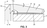
Fig. 3 ] est une vue de détail desfigures 1 et 2 , - [
Fig. 4 ] est une vue en perspective de l'assemblage de lafigure 1 , - [
Fig. 5 ] est une vue en perspective de l'assemblage de lafigure 1 , dans laquelle les première et seconde pièces ont été retirées, - [
Fig. 6 ] est une vue en coupe d'un assemblage selon une autre forme de réalisation de l'invention, - [
Fig. 7 ] est une vue de détail de lafigure 6 , - [
Fig. 8 ] est une vue de détail desfigures 6 et 7 , - [
Fig. 9 ] est une vue en perspective de l'assemblage de lafigure 6 , - [
Fig. 10 ] est une vue en perspective de l'assemblage de lafigure 6 , dans laquelle les première et seconde pièces ont été retirées. - Les
figures 1 à 5 illustrent un assemblage 1 pour une turbomachine d'aéronef selon une première forme de réalisation de l'invention. L'assemblage 1 comporte une première pièce 2 réalisée en matériau composite à matrice céramique, une seconde pièce métallique 3, un boulon 4, une douille 5 et une entretoise 6. - Les pièces 2, 3 assemblées sont formées par des parois coaxiales cylindriques ou en portion de cylindre. Le boulon 4 comporte une vis 7 et un écrou 8. La vis 7 comporte une première extrémité comportant une tête conique 9 et une seconde extrémité filetée 10 sur laquelle est vissé l'écrou 8. La vis 7 traverse des orifices 11, 12 de la première pièce 2 et de la seconde pièce 3. Un lamage 13 est formé autour de l'orifice 11 de la première pièce 2. Un lamage 14 est également formé autour de l'orifice 12 de la seconde pièce 3.
- La douille 5 comporte une partie cylindrique 15 entourant la vis 7 et engagée dans les orifices 11, 12. Une extrémité de la partie cylindrique 15 est prolongée par une collerette annulaire 16 de forme générale tronconique.
- En particulier, la collerette 16 comporte une surface d'appui tronconique 17 tournée en regard d'une surface d'appui complémentaire 13 de la première pièce 2. Ladite surface d'appui complémentaire est formée par la surface de fond du lamage 13 de la première pièce 2, la collerette 16 étant logée en partie dans ledit lamage 13.
- La surface d'appui 17 de la collerette 16 forme un angle α (
Figures 2 et3 ) avec la surface d'appui complémentaire 13 de la première pièce 2 de sorte que seule une zone périphérique externe de ladite surface d'appui 17 de la collerette 16 vienne au contact de la surface d'appui complémentaire 13 de la première pièce 2, dans un état non serré du boulon 4. La collerette 16 est par ailleurs déformable de sorte que, lors du serrage dudit écrou 8 sur la vis 7, une plus grande zone de la surface d'appui 17 de la collerette 16 vient en appui sur la surface d'appui complémentaire 13 de la première pièce 2. - La collerette 16 peut être en appui sur la première pièce 2, soit directement, soit indirectement, par exemple par l'intermédiaire d'une rondelle 23 (
figure 3 ). - Dans l'état non serré du boulon 4, l'angle α entre la surface d'appui 17 de la collerette 16 par rapport à la surface d'appui complémentaire 13 de la première pièce 2 est compris entre 0,1 et 6°.
- Dans l'état serré du boulon 4, cet angle α peut être nul de sorte que toute la surface d'appui 17 de la collerette 16 est en appui sur la surface d'appui complémentaire 13 de la première pièce 2. La collerette 16 est effilée en direction de sa périphérie externe.
- Par ailleurs, une gorge annulaire 17a en renfoncement s'étend au niveau de la périphérie interne de la surface d'appui 17, de façon à faciliter la déformation de la collerette 16.
- La gorge 17a peut comporter une section dont au moins une partie présente une forme de portion de cercle. Ladite section est vue selon un plan s'étendant selon l'axe X de collerette 16, qui est confondu avec l'axe de la vis 7, de l'écrou 8, de la douille 5 et de l'entretoise 6. Le rayon R de la partie en forme de portion de cercle peut être compris entre 0,2 et 1,4 mm par exemple.
- La surface 18 de la collerette 16 opposée à la surface d'appui 17 est une surface tronconique. La tête 9 de la vis 7 vient en appui sur un chanfrein interne 19 de la douille 5.
- La surface 18 est inclinée d'un angle β par rapport à un plan perpendiculaire à l'axe de la collerette. Ledit angle β peut être compris entre 5 et 30°.
- L'épaisseur e de la collerette 16 au niveau de sa périphérie externe peut être comprise entre 0,6 et 1,5 mm. L'épaisseur est la dimension de la collerette 16 suivant l'axe X de la collerette 16.
- La distance d, selon l'axe X de la collerette 19, entre la périphérie interne de la surface d'appui 17 et la périphérie externe de la surface 18, peut être comprise entre 1 et 5 mm.
- L'entretoise 6 est annulaire et comporte une première extrémité 20 en appui sur la surface de fond du lamage 14 de la seconde pièce 3 et une seconde extrémité 21 en appui sur l'écrou 8. L'entretoise 6 présente une forme tronconique évasée en direction de la première extrémité 20. Le diamètre externe et le diamètre interne de la première extrémité 20 correspondent globalement aux diamètres externe et interne de la collerette 16.
- L'entretoise 6 présente un évidement interne 22 servant à loger partiellement la partie cylindrique 15 de la douille 5. Ladite partie cylindrique 15 est par ailleurs centrée dans ledit évidement interne 22. L'entretoise 6 est réalisée dans un matériau présentant un coefficient de dilatation plus important que celui de la vis 7, de manière à maintenir le serrage des deux pièces 2, 3 ensemble malgré d'éventuels effets de dilatation différentiels.
- La vis 7 est par exemple réalisée en un matériau de type Inconel 718 ou Waspaloy (marques déposées). L'entretoise 6 est par exemple réalisée en un matériau de type A286.
- Les
figures 6 à 10 illustrent un assemblage selon une autre forme de réalisation de l'invention, qui diffère de la forme de réalisation illustrée auxfigures 1 à 5 en ce que l'assemblage est dépourvu de douille 5, la collerette 16 étant formée par la tête 9 de la vis 7. La vis 7 est centrée dans l'entretoise 6, au niveau de l'extrémité 20 de ladite entretoise 6. Dans cette forme de réalisation également, des rondelles 23 peuvent être montées entre la collerette 16 et la première pièce 2, d'une part, et entre l'entretoise 6 et la seconde pièce 3, d'autre part. - Par ailleurs, l'assemblage 1 est dépourvu d'écrou 8 distinct, l'écrou 8 étant ici formé par l'extrémité correspondante 21 de l'entretoise 6.
Claims (11)
- Assemblage (1) pour une turbomachine, ledit assemblage (1) comportant au moins une première pièce (2) et une seconde pièce (3), et au moins un boulon (4) comportant une vis (7) coopérant avec un écrou (8), ladite vis (7) s'étendant au travers d'un orifice (11) de la première pièce (2) et d'un orifice (12) de la seconde pièce (3), le boulon (4) comportant en outre un organe d'appui comprenant une collerette (16) annulaire montée entre la vis (7) ou l'écrou (8), d'une part, et la première pièce (2), d'autre part, ladite collerette (16) comportant une surface d'appui (17) venant en appui, au moins partiellement, sur une surface d'appui complémentaire (13) de la première pièce (2), ladite surface d'appui (17) de la collerette (16) étant tronconique, caractérisé en ce que ladite surface d'appui (17) de la collerette (16) forme un angle (α) avec la surface d'appui complémentaire (13) de la première pièce (2) de sorte que seule une zone périphérique externe de ladite surface d'appui (17) de la collerette (16) vienne au contact de la surface d'appui complémentaire (13) de la première pièce (2), dans un état non serré du boulon (4), ladite collerette (16) étant déformable de sorte que, lors du serrage dudit écrou (8) sur la vis (7), une plus grande zone de la surface d'appui (17) de la collerette (16) vient en appui sur la surface d'appui complémentaire (13) de la première pièce (2), ledit organe d'appui comportant une gorge annulaire en renfoncement s'étendant au niveau de la périphérie interne de la collerette.
- Assemblage (1) selon la revendication précédente, caractérisé en ce que la gorge comporte une section dont au moins une partie présente une forme de portion de cercle.
- Assemblage (1) selon la revendication précédente, caractérisé en ce que le rayon de la partie en forme de portion de cercle peut être compris entre 0,2 et 1,4 mm.
- Assemblage (1) selon l'une des revendications précédentes, caractérisé en ce que, dans l'état non serré du boulon (4), l'angle (α) entre la surface d'appui (17) de la collerette (16) par rapport à la surface d'appui complémentaire (13) de la première pièce (2) est compris entre 0,1 et 6°.
- Assemblage (1) selon l'une des revendications précédentes, caractérisé en ce que la collerette (16) est effilée en direction de sa périphérie externe.
- Assemblage (1) selon l'une des revendications précédentes, caractérisé en ce que la première pièce (2) est réalisée en matériau céramique à matrice composite.
- Assemblage (1) selon l'une des revendications précédentes, caractérisé en ce qu'il comporte une entretoise (6) montée entre la seconde pièce (3) et une partie du boulon (4), ladite entretoise (6) étant réalisée dans un matériau présentant un coefficient de dilatation plus important que celui de la vis (7).
- Assemblage (1) selon l'une des revendications précédentes, caractérisé en ce qu'il comporte une douille (5), ladite douille (5) comprenant une partie cylindrique (15) entourant la vis (7) et logée au moins en partie dans les orifices (11, 12) des première et seconde pièces (3), ladite collerette (16) étant formée par la douille (5) et s'étendant depuis une extrémité de la partie cylindrique (15).
- Assemblage (1) selon l'une des revendications précédentes, caractérisé en ce que la collerette (16) est formée à une extrémité de la vis (7).
- Assemblage (1) selon l'une des revendications précédentes, caractérisé en ce que l'entretoise (6) comporte une extrémité (20) en appui sur la seconde pièce (3) et une extrémité (21) en appui sur l'écrou (8) ou sur une partie de la vis (7).
- Assemblage (1) selon l'une des revendications précédentes, caractérisé en ce que la collerette (16) est logée, au moins en partie, dans un lamage (13) de la première pièce.
Applications Claiming Priority (3)
| Application Number | Priority Date | Filing Date | Title |
|---|---|---|---|
| FR2013280A FR3117556B1 (fr) | 2020-12-15 | 2020-12-15 | Assemblage pour une turbomachine |
| FR2103417A FR3117557B1 (fr) | 2020-12-15 | 2021-04-01 | Assemblage pour une turbomachine |
| PCT/FR2021/052096 WO2022129723A1 (fr) | 2020-12-15 | 2021-11-25 | Assemblage pour une turbomachine |
Publications (2)
| Publication Number | Publication Date |
|---|---|
| EP4264063A1 EP4264063A1 (fr) | 2023-10-25 |
| EP4264063B1 true EP4264063B1 (fr) | 2024-10-23 |
Family
ID=79020934
Family Applications (1)
| Application Number | Title | Priority Date | Filing Date |
|---|---|---|---|
| EP21830454.1A Active EP4264063B1 (fr) | 2020-12-15 | 2021-11-25 | Assemblage pour une turbomachine |
Country Status (3)
| Country | Link |
|---|---|
| US (1) | US12258879B2 (fr) |
| EP (1) | EP4264063B1 (fr) |
| WO (1) | WO2022129723A1 (fr) |
Families Citing this family (3)
| Publication number | Priority date | Publication date | Assignee | Title |
|---|---|---|---|---|
| FR3117556B1 (fr) * | 2020-12-15 | 2022-11-11 | Safran Ceram | Assemblage pour une turbomachine |
| FR3164259A1 (fr) | 2024-07-08 | 2026-01-09 | Safran Aircraft Engines | Coupelle d’assemblage, assemblage et procédé d’assemblage |
| FR3165606A1 (fr) * | 2024-08-16 | 2026-02-20 | Segula Engineering | Moyens d’assemblage structurel ou semi-structurel pour assembler structurellement ou semi-structurellement au moins deux éléments structurels et/ou semi-structurels en matériaux composites. |
Family Cites Families (7)
| Publication number | Priority date | Publication date | Assignee | Title |
|---|---|---|---|---|
| US4834569A (en) * | 1987-05-13 | 1989-05-30 | The Boeing Company | Thermal expansion compensating joint assembly |
| US5848874A (en) * | 1997-05-13 | 1998-12-15 | United Technologies Corporation | Gas turbine stator vane assembly |
| FR3006394B1 (fr) * | 2013-05-28 | 2015-06-19 | Herakles | Assemblage a liaison auto-serrante en temperature |
| DE102015101258A1 (de) * | 2014-01-28 | 2015-07-30 | Richard Bergner Verbindungstechnik Gmbh & Co. Kg | Verfahren zur Herstellung einer Montageeinheit und Befestigereinheit zur Durchführung des Verfahrens |
| FR3038942B1 (fr) * | 2015-07-17 | 2018-03-02 | Safran Ceramics | Assemblage par liaison mecanique comportant au moins une piece en materiau composite |
| FR3044701B1 (fr) * | 2015-12-03 | 2017-11-24 | Snecma | Rotor pour une turbomachine ou un banc d'essai |
| US10167885B2 (en) * | 2016-03-21 | 2019-01-01 | United Technologies Corporation | Mechanical joint with a flanged retainer |
-
2021
- 2021-11-25 EP EP21830454.1A patent/EP4264063B1/fr active Active
- 2021-11-25 US US18/266,761 patent/US12258879B2/en active Active
- 2021-11-25 WO PCT/FR2021/052096 patent/WO2022129723A1/fr not_active Ceased
Also Published As
| Publication number | Publication date |
|---|---|
| EP4264063A1 (fr) | 2023-10-25 |
| WO2022129723A1 (fr) | 2022-06-23 |
| US20240052759A1 (en) | 2024-02-15 |
| US12258879B2 (en) | 2025-03-25 |
Similar Documents
| Publication | Publication Date | Title |
|---|---|---|
| EP3325819B1 (fr) | Assemblage par liaison mécanique comportant au moins une pièce en matériau composite | |
| EP4264063A1 (fr) | Assemblage pour une turbomachine | |
| EP0715086B1 (fr) | Dispositif pour la fixation d'un élément sur la caisse d'un véhicule automobile | |
| EP1950392B1 (fr) | Dispositif d'assemblage de deux ensembles, par exemple pour stator de turbomachine | |
| CA2911465C (fr) | Assemblage a liaison auto-serrante en temperature | |
| CA2824693C (fr) | Dispositif de fixation | |
| FR2721683A1 (fr) | Structure d'assemblage pour assembler un élément en dérivation à une canalisation de carburant sous haute pression. | |
| EP3755908B1 (fr) | Dispositif de retenue pour organe filete, notamment pour ecrou | |
| EP4264062B1 (fr) | Assemblage pour une turbomachine | |
| FR3137367A1 (fr) | Structure en treillis renforcée et aéronef comprenant au moins une telle structure | |
| EP0679559B1 (fr) | Mécanisme d'essuie-glace comportant un dispositif d'articulation perfectionné entre une bielle et une manivelle du mécanisme | |
| FR3118785A1 (fr) | Piece de blocage pour assemblage d’elements de turbomachine comprenant des moyens fusibles et turbomachine correspondante | |
| EP0397561A1 (fr) | Tête de coupe à jet d'oxygène | |
| EP0988446B1 (fr) | Dispositif d'ancrage pour un organe d'activation de tuyere orientable | |
| EP0128080B1 (fr) | Dispositif d'assemblage de matériaux composites | |
| FR3026151A1 (fr) | Dispositif d'assemblage a ecrou-barillet, ensemble structurel d'aeronef comprenant un tel dispositif, et procede d'assemblage correspondant | |
| EP3859170B1 (fr) | Boulon comprenant un écrou et au moins une rondelle obtenue par durcissement d'un matériau pâteux, procédé de montage dudit boulon et assemblage comportant au moins un tel boulon | |
| BE1032906B1 (fr) | Ensemble vissé et précontraint présentant une conception améliorée à des fins de maintien des performances sous températures cryogéniques | |
| FR2594202A1 (fr) | Robinet a tournant spherique | |
| FR3021299A1 (fr) | Attache moteur pour un aeronef | |
| FR2803695A1 (fr) | Dispositif de fixation d'un organe electrique sur un support en materiau electrique conducteur | |
| FR3076815A1 (fr) | Assemblage d'aeronef comprenant un capuchon de recouvrement d'une fixation | |
| FR2937696A1 (fr) | Systeme de vis et rondelle pour la fixation de panneau de carenage d'avion | |
| FR2801079A1 (fr) | Dispositif de fixation |
Legal Events
| Date | Code | Title | Description |
|---|---|---|---|
| STAA | Information on the status of an ep patent application or granted ep patent |
Free format text: STATUS: UNKNOWN |
|
| STAA | Information on the status of an ep patent application or granted ep patent |
Free format text: STATUS: THE INTERNATIONAL PUBLICATION HAS BEEN MADE |
|
| PUAI | Public reference made under article 153(3) epc to a published international application that has entered the european phase |
Free format text: ORIGINAL CODE: 0009012 |
|
| STAA | Information on the status of an ep patent application or granted ep patent |
Free format text: STATUS: REQUEST FOR EXAMINATION WAS MADE |
|
| 17P | Request for examination filed |
Effective date: 20230620 |
|
| AK | Designated contracting states |
Kind code of ref document: A1 Designated state(s): AL AT BE BG CH CY CZ DE DK EE ES FI FR GB GR HR HU IE IS IT LI LT LU LV MC MK MT NL NO PL PT RO RS SE SI SK SM TR |
|
| DAV | Request for validation of the european patent (deleted) | ||
| DAX | Request for extension of the european patent (deleted) | ||
| GRAP | Despatch of communication of intention to grant a patent |
Free format text: ORIGINAL CODE: EPIDOSNIGR1 |
|
| STAA | Information on the status of an ep patent application or granted ep patent |
Free format text: STATUS: GRANT OF PATENT IS INTENDED |
|
| INTG | Intention to grant announced |
Effective date: 20240712 |
|
| GRAS | Grant fee paid |
Free format text: ORIGINAL CODE: EPIDOSNIGR3 |
|
| GRAA | (expected) grant |
Free format text: ORIGINAL CODE: 0009210 |
|
| STAA | Information on the status of an ep patent application or granted ep patent |
Free format text: STATUS: THE PATENT HAS BEEN GRANTED |
|
| AK | Designated contracting states |
Kind code of ref document: B1 Designated state(s): AL AT BE BG CH CY CZ DE DK EE ES FI FR GB GR HR HU IE IS IT LI LT LU LV MC MK MT NL NO PL PT RO RS SE SI SK SM TR |
|
| REG | Reference to a national code |
Ref country code: GB Ref legal event code: FG4D Free format text: NOT ENGLISH |
|
| REG | Reference to a national code |
Ref country code: CH Ref legal event code: EP |
|
| REG | Reference to a national code |
Ref country code: DE Ref legal event code: R096 Ref document number: 602021020791 Country of ref document: DE |
|
| REG | Reference to a national code |
Ref country code: IE Ref legal event code: FG4D Free format text: LANGUAGE OF EP DOCUMENT: FRENCH |
|
| REG | Reference to a national code |
Ref country code: LT Ref legal event code: MG9D |
|
| REG | Reference to a national code |
Ref country code: NL Ref legal event code: MP Effective date: 20241023 |
|
| REG | Reference to a national code |
Ref country code: AT Ref legal event code: MK05 Ref document number: 1735046 Country of ref document: AT Kind code of ref document: T Effective date: 20241023 |
|
| PG25 | Lapsed in a contracting state [announced via postgrant information from national office to epo] |
Ref country code: NL Free format text: LAPSE BECAUSE OF FAILURE TO SUBMIT A TRANSLATION OF THE DESCRIPTION OR TO PAY THE FEE WITHIN THE PRESCRIBED TIME-LIMIT Effective date: 20241023 |
|
| PG25 | Lapsed in a contracting state [announced via postgrant information from national office to epo] |
Ref country code: NL Free format text: LAPSE BECAUSE OF FAILURE TO SUBMIT A TRANSLATION OF THE DESCRIPTION OR TO PAY THE FEE WITHIN THE PRESCRIBED TIME-LIMIT Effective date: 20241023 |
|
| PG25 | Lapsed in a contracting state [announced via postgrant information from national office to epo] |
Ref country code: IS Free format text: LAPSE BECAUSE OF FAILURE TO SUBMIT A TRANSLATION OF THE DESCRIPTION OR TO PAY THE FEE WITHIN THE PRESCRIBED TIME-LIMIT Effective date: 20250223 Ref country code: HR Free format text: LAPSE BECAUSE OF FAILURE TO SUBMIT A TRANSLATION OF THE DESCRIPTION OR TO PAY THE FEE WITHIN THE PRESCRIBED TIME-LIMIT Effective date: 20241023 Ref country code: PT Free format text: LAPSE BECAUSE OF FAILURE TO SUBMIT A TRANSLATION OF THE DESCRIPTION OR TO PAY THE FEE WITHIN THE PRESCRIBED TIME-LIMIT Effective date: 20250224 |
|
| PG25 | Lapsed in a contracting state [announced via postgrant information from national office to epo] |
Ref country code: FI Free format text: LAPSE BECAUSE OF FAILURE TO SUBMIT A TRANSLATION OF THE DESCRIPTION OR TO PAY THE FEE WITHIN THE PRESCRIBED TIME-LIMIT Effective date: 20241023 |
|
| PG25 | Lapsed in a contracting state [announced via postgrant information from national office to epo] |
Ref country code: BG Free format text: LAPSE BECAUSE OF FAILURE TO SUBMIT A TRANSLATION OF THE DESCRIPTION OR TO PAY THE FEE WITHIN THE PRESCRIBED TIME-LIMIT Effective date: 20241023 |
|
| PG25 | Lapsed in a contracting state [announced via postgrant information from national office to epo] |
Ref country code: ES Free format text: LAPSE BECAUSE OF FAILURE TO SUBMIT A TRANSLATION OF THE DESCRIPTION OR TO PAY THE FEE WITHIN THE PRESCRIBED TIME-LIMIT Effective date: 20241023 |
|
| PG25 | Lapsed in a contracting state [announced via postgrant information from national office to epo] |
Ref country code: NO Free format text: LAPSE BECAUSE OF FAILURE TO SUBMIT A TRANSLATION OF THE DESCRIPTION OR TO PAY THE FEE WITHIN THE PRESCRIBED TIME-LIMIT Effective date: 20250123 |
|
| PG25 | Lapsed in a contracting state [announced via postgrant information from national office to epo] |
Ref country code: LV Free format text: LAPSE BECAUSE OF FAILURE TO SUBMIT A TRANSLATION OF THE DESCRIPTION OR TO PAY THE FEE WITHIN THE PRESCRIBED TIME-LIMIT Effective date: 20241023 Ref country code: AT Free format text: LAPSE BECAUSE OF FAILURE TO SUBMIT A TRANSLATION OF THE DESCRIPTION OR TO PAY THE FEE WITHIN THE PRESCRIBED TIME-LIMIT Effective date: 20241023 Ref country code: GR Free format text: LAPSE BECAUSE OF FAILURE TO SUBMIT A TRANSLATION OF THE DESCRIPTION OR TO PAY THE FEE WITHIN THE PRESCRIBED TIME-LIMIT Effective date: 20250124 |
|
| PG25 | Lapsed in a contracting state [announced via postgrant information from national office to epo] |
Ref country code: PL Free format text: LAPSE BECAUSE OF FAILURE TO SUBMIT A TRANSLATION OF THE DESCRIPTION OR TO PAY THE FEE WITHIN THE PRESCRIBED TIME-LIMIT Effective date: 20241023 |
|
| PG25 | Lapsed in a contracting state [announced via postgrant information from national office to epo] |
Ref country code: RS Free format text: LAPSE BECAUSE OF FAILURE TO SUBMIT A TRANSLATION OF THE DESCRIPTION OR TO PAY THE FEE WITHIN THE PRESCRIBED TIME-LIMIT Effective date: 20250123 |
|
| REG | Reference to a national code |
Ref country code: CH Ref legal event code: PL |
|
| PG25 | Lapsed in a contracting state [announced via postgrant information from national office to epo] |
Ref country code: SM Free format text: LAPSE BECAUSE OF FAILURE TO SUBMIT A TRANSLATION OF THE DESCRIPTION OR TO PAY THE FEE WITHIN THE PRESCRIBED TIME-LIMIT Effective date: 20241023 |
|
| PG25 | Lapsed in a contracting state [announced via postgrant information from national office to epo] |
Ref country code: MC Free format text: LAPSE BECAUSE OF FAILURE TO SUBMIT A TRANSLATION OF THE DESCRIPTION OR TO PAY THE FEE WITHIN THE PRESCRIBED TIME-LIMIT Effective date: 20241023 |
|
| PG25 | Lapsed in a contracting state [announced via postgrant information from national office to epo] |
Ref country code: DK Free format text: LAPSE BECAUSE OF FAILURE TO SUBMIT A TRANSLATION OF THE DESCRIPTION OR TO PAY THE FEE WITHIN THE PRESCRIBED TIME-LIMIT Effective date: 20241023 |
|
| PG25 | Lapsed in a contracting state [announced via postgrant information from national office to epo] |
Ref country code: LU Free format text: LAPSE BECAUSE OF NON-PAYMENT OF DUE FEES Effective date: 20241125 |
|
| REG | Reference to a national code |
Ref country code: CH Ref legal event code: PL |
|
| PG25 | Lapsed in a contracting state [announced via postgrant information from national office to epo] |
Ref country code: EE Free format text: LAPSE BECAUSE OF FAILURE TO SUBMIT A TRANSLATION OF THE DESCRIPTION OR TO PAY THE FEE WITHIN THE PRESCRIBED TIME-LIMIT Effective date: 20241023 |
|
| PG25 | Lapsed in a contracting state [announced via postgrant information from national office to epo] |
Ref country code: CH Free format text: LAPSE BECAUSE OF NON-PAYMENT OF DUE FEES Effective date: 20241130 |
|
| PG25 | Lapsed in a contracting state [announced via postgrant information from national office to epo] |
Ref country code: RO Free format text: LAPSE BECAUSE OF FAILURE TO SUBMIT A TRANSLATION OF THE DESCRIPTION OR TO PAY THE FEE WITHIN THE PRESCRIBED TIME-LIMIT Effective date: 20241023 |
|
| REG | Reference to a national code |
Ref country code: DE Ref legal event code: R097 Ref document number: 602021020791 Country of ref document: DE |
|
| PG25 | Lapsed in a contracting state [announced via postgrant information from national office to epo] |
Ref country code: SK Free format text: LAPSE BECAUSE OF FAILURE TO SUBMIT A TRANSLATION OF THE DESCRIPTION OR TO PAY THE FEE WITHIN THE PRESCRIBED TIME-LIMIT Effective date: 20241023 |
|
| PG25 | Lapsed in a contracting state [announced via postgrant information from national office to epo] |
Ref country code: CZ Free format text: LAPSE BECAUSE OF FAILURE TO SUBMIT A TRANSLATION OF THE DESCRIPTION OR TO PAY THE FEE WITHIN THE PRESCRIBED TIME-LIMIT Effective date: 20241023 |
|
| PG25 | Lapsed in a contracting state [announced via postgrant information from national office to epo] |
Ref country code: IT Free format text: LAPSE BECAUSE OF FAILURE TO SUBMIT A TRANSLATION OF THE DESCRIPTION OR TO PAY THE FEE WITHIN THE PRESCRIBED TIME-LIMIT Effective date: 20241023 |
|
| REG | Reference to a national code |
Ref country code: BE Ref legal event code: MM Effective date: 20241130 |
|
| PLBE | No opposition filed within time limit |
Free format text: ORIGINAL CODE: 0009261 |
|
| STAA | Information on the status of an ep patent application or granted ep patent |
Free format text: STATUS: NO OPPOSITION FILED WITHIN TIME LIMIT |
|
| PG25 | Lapsed in a contracting state [announced via postgrant information from national office to epo] |
Ref country code: SE Free format text: LAPSE BECAUSE OF FAILURE TO SUBMIT A TRANSLATION OF THE DESCRIPTION OR TO PAY THE FEE WITHIN THE PRESCRIBED TIME-LIMIT Effective date: 20241023 |
|
| 26N | No opposition filed |
Effective date: 20250724 |
|
| PG25 | Lapsed in a contracting state [announced via postgrant information from national office to epo] |
Ref country code: BE Free format text: LAPSE BECAUSE OF NON-PAYMENT OF DUE FEES Effective date: 20241130 |
|
| PG25 | Lapsed in a contracting state [announced via postgrant information from national office to epo] |
Ref country code: IE Free format text: LAPSE BECAUSE OF NON-PAYMENT OF DUE FEES Effective date: 20241125 |
|
| PGFP | Annual fee paid to national office [announced via postgrant information from national office to epo] |
Ref country code: DE Payment date: 20251118 Year of fee payment: 5 |
|
| PGFP | Annual fee paid to national office [announced via postgrant information from national office to epo] |
Ref country code: GB Payment date: 20251125 Year of fee payment: 5 |
|
| PGFP | Annual fee paid to national office [announced via postgrant information from national office to epo] |
Ref country code: FR Payment date: 20251125 Year of fee payment: 5 |
|
| PG25 | Lapsed in a contracting state [announced via postgrant information from national office to epo] |
Ref country code: HU Free format text: LAPSE BECAUSE OF FAILURE TO SUBMIT A TRANSLATION OF THE DESCRIPTION OR TO PAY THE FEE WITHIN THE PRESCRIBED TIME-LIMIT; INVALID AB INITIO Effective date: 20211125 |
|
| PG25 | Lapsed in a contracting state [announced via postgrant information from national office to epo] |
Ref country code: CY Free format text: LAPSE BECAUSE OF FAILURE TO SUBMIT A TRANSLATION OF THE DESCRIPTION OR TO PAY THE FEE WITHIN THE PRESCRIBED TIME-LIMIT; INVALID AB INITIO Effective date: 20211125 |