EP4264206B1 - Verfahren und system zur bestimmung von durch eine vorrichtung erzeugten schwingungen - Google Patents
Verfahren und system zur bestimmung von durch eine vorrichtung erzeugten schwingungen Download PDFInfo
- Publication number
- EP4264206B1 EP4264206B1 EP21847840.2A EP21847840A EP4264206B1 EP 4264206 B1 EP4264206 B1 EP 4264206B1 EP 21847840 A EP21847840 A EP 21847840A EP 4264206 B1 EP4264206 B1 EP 4264206B1
- Authority
- EP
- European Patent Office
- Prior art keywords
- vibration
- accelerometer
- measurements
- contribution
- amplitude
- Prior art date
- Legal status (The legal status is an assumption and is not a legal conclusion. Google has not performed a legal analysis and makes no representation as to the accuracy of the status listed.)
- Active
Links
Images


Classifications
-
- G—PHYSICS
- G01—MEASURING; TESTING
- G01P—MEASURING LINEAR OR ANGULAR SPEED, ACCELERATION, DECELERATION, OR SHOCK; INDICATING PRESENCE, ABSENCE, OR DIRECTION, OF MOVEMENT
- G01P15/00—Measuring acceleration; Measuring deceleration; Measuring shock, i.e. sudden change of acceleration
- G01P15/02—Measuring acceleration; Measuring deceleration; Measuring shock, i.e. sudden change of acceleration by making use of inertia forces using solid seismic masses
- G01P15/08—Measuring acceleration; Measuring deceleration; Measuring shock, i.e. sudden change of acceleration by making use of inertia forces using solid seismic masses with conversion into electric or magnetic values
- G01P15/097—Measuring acceleration; Measuring deceleration; Measuring shock, i.e. sudden change of acceleration by making use of inertia forces using solid seismic masses with conversion into electric or magnetic values by vibratory elements
-
- G—PHYSICS
- G01—MEASURING; TESTING
- G01H—MEASUREMENT OF MECHANICAL VIBRATIONS OR ULTRASONIC, SONIC OR INFRASONIC WAVES
- G01H1/00—Measuring characteristics of vibrations in solids by using direct conduction to the detector
-
- G—PHYSICS
- G01—MEASURING; TESTING
- G01M—TESTING STATIC OR DYNAMIC BALANCE OF MACHINES OR STRUCTURES; TESTING OF STRUCTURES OR APPARATUS, NOT OTHERWISE PROVIDED FOR
- G01M13/00—Testing of machine parts
-
- G—PHYSICS
- G01—MEASURING; TESTING
- G01M—TESTING STATIC OR DYNAMIC BALANCE OF MACHINES OR STRUCTURES; TESTING OF STRUCTURES OR APPARATUS, NOT OTHERWISE PROVIDED FOR
- G01M13/00—Testing of machine parts
- G01M13/02—Gearings; Transmission mechanisms
- G01M13/028—Acoustic or vibration analysis
-
- G—PHYSICS
- G01—MEASURING; TESTING
- G01P—MEASURING LINEAR OR ANGULAR SPEED, ACCELERATION, DECELERATION, OR SHOCK; INDICATING PRESENCE, ABSENCE, OR DIRECTION, OF MOVEMENT
- G01P15/00—Measuring acceleration; Measuring deceleration; Measuring shock, i.e. sudden change of acceleration
- G01P15/02—Measuring acceleration; Measuring deceleration; Measuring shock, i.e. sudden change of acceleration by making use of inertia forces using solid seismic masses
- G01P15/08—Measuring acceleration; Measuring deceleration; Measuring shock, i.e. sudden change of acceleration by making use of inertia forces using solid seismic masses with conversion into electric or magnetic values
- G01P15/0891—Measuring acceleration; Measuring deceleration; Measuring shock, i.e. sudden change of acceleration by making use of inertia forces using solid seismic masses with conversion into electric or magnetic values with indication of predetermined acceleration values
Definitions
- CBM Condition-Based Monitoring
- the sensors are used to monitor various parameters indicative of the operational condition of the equipment or asset.
- the sensed parameters are analyzed with the intention of identifying early performance degradation of the asset, with the intention of repairing the asset prior to failure or significant performance degradation, thereby reducing equipment downtime.
- CN110849462A describes, in accordance with its abstract, a rolling mill vibration signal separation method based on sparse feature similarity.
- the continuous rolling mill vibration signal separation method comprises the steps of: arranging acceleration sensors at one or more different positions on the surface of a sensitive part of a rotating component of a continuous rolling mill, and acquiring vibration signals, namely observation signals, of each vibration source during operation; acquiring sparse representation of each path of acquired vibration signals under an optimal atom set by adopting a sparse feature extraction method based on time-frequency spectrum segmentation; then clustering all atoms extracted through sparse representation according to structural similarity, estimating a number of vibration sources, and updating a sparse representation result by adopting the atoms corresponding to each clustering center; and finally, estimating a hybrid matrix based on a clustering coefficient corresponding to the new sparse representation result, and further calculating an independent signal of each vibration source to realize separation of vibration signals of the continuous rolling mill.
- DE10342683A1 describes vibration parameters which are determined from detected acceleration data.
- One accelerometer is used to detect measurement values from the corners of a triangle formed at arbitrary points on the mirror surface, and another accelerometer is used to detect measurement values from the mirror housing or vehicle body to which the mirror is fixed. The measurement values are fed to an analysis unit for data evaluation.
- An independent claim is included for an apparatus for detecting vehicle mirror vibration.
- US2019101104A1 describes a first vibration sensor measuring vibration of a bearing.
- a second vibration sensor for measuring background noise received by the first vibration sensor is installed so as not to receive vibration of the bearing.
- a data acquisition device receives a first signal that is a measurement signal of the first vibration sensor and a second signal that is a measurement signal of the second vibration sensor and outputs a third signal obtained by subtracting the second signal from the first signal as data indicating vibration of the bearing.
- a computer-implemented method for determining vibrations generated by a device is provided according to claim 1.
- a system for determining vibrations generated by a device is provided according to claim 11.
- a non-transitory computer-readable storage medium is provided according to claim 15. Advantageous embodiments are defined in the dependent claims.
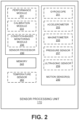
- Embodiments described herein may be discussed in the general context of processor-executable instructions residing on some form of non-transitory processor-readable medium, such as program modules, executed by one or more computers or other devices.
- program modules include routines, programs, objects, components, data structures, etc., that perform particular tasks or implement particular abstract data types.
- the functionality of the program modules may be combined or distributed as desired in various embodiments.
- a single block may be described as performing a function or functions; however, in actual practice, the function or functions performed by that block may be performed in a single component or across multiple components, and/or may be performed using hardware, using software, or using a combination of hardware and software.
- various illustrative components, blocks, modules, logic, circuits, and steps have been described generally in terms of their functionality. Whether such functionality is implemented as hardware or software depends upon the particular application and design constraints imposed on the overall system. Skilled artisans may implement the described functionality in varying ways for each particular application, but such implementation decisions should not be interpreted as causing a departure from the scope of the present disclosure.
- the example device vibration sensing system and/or electronic device described herein may include components other than those shown, including well-known components.
- Various techniques described herein may be implemented in hardware, software, firmware, or any combination thereof, unless specifically described as being implemented in a specific manner. Any features described as modules or components may also be implemented together in an integrated logic device or separately as discrete but interoperable logic devices. If implemented in software, the techniques may be realized at least in part by a non-transitory processor-readable storage medium comprising instructions that, when executed, perform one or more of the methods described herein.
- the non-transitory processor-readable data storage medium may form part of a computer program product, which may include packaging materials.
- the non-transitory processor-readable storage medium may comprise random access memory (RAM) such as synchronous dynamic random access memory (SDRAM), read only memory (ROM), non-volatile random access memory (NVRAM), electrically erasable programmable read-only memory (EEPROM), FLASH memory, other known storage media, and the like.
- RAM synchronous dynamic random access memory
- ROM read only memory
- NVRAM non-volatile random access memory
- EEPROM electrically erasable programmable read-only memory
- FLASH memory other known storage media, and the like.
- the techniques additionally, or alternatively, may be realized at least in part by a processor-readable communication medium that carries or communicates code in the form of instructions or data structures and that can be accessed, read, and/or executed by a computer or other processor.
- processors such as one or more motion processing units (MPUs), sensor processing units (SPUs), host processor(s) or core(s) thereof, digital signal processors (DSPs), general purpose microprocessors, application specific integrated circuits (ASICs), application specific instruction set processors (ASIPs), field programmable gate arrays (FPGAs), a programmable logic controller (PLC), a complex programmable logic device (CPLD), a discrete gate or transistor logic, discrete hardware components, or any combination thereof designed to perform the functions described herein, or other equivalent integrated or discrete logic circuitry.
- MPUs motion processing units
- SPUs sensor processing units
- DSPs digital signal processors
- ASIPs application specific instruction set processors
- FPGAs field programmable gate arrays
- PLC programmable logic controller
- CPLD complex programmable logic device
- processor may refer to any of the foregoing structures or any other structure suitable for implementation of the techniques described herein.
- processor can refer to substantially any computing processing unit or device comprising, but not limited to comprising, single-core processors; single-processors with software multithread execution capability; multi-core processors; multi-core processors with software multithread execution capability; multi-core processors with hardware multithread technology; parallel platforms; and parallel platforms with distributed shared memory.
- processors can exploit nano-scale architectures such as, but not limited to, molecular and quantum-dot based transistors, switches and gates, in order to optimize space usage or enhance performance of user equipment.
- a processor may also be implemented as a combination of computing processing units.
- a general purpose processor may be a microprocessor, but in the alternative, the processor may be any processor, controller, microcontroller, or state machine.
- a processor may also be implemented as a combination of computing devices, e.g., a combination of an SPU/MPU and a microprocessor, a plurality of microprocessors, one or more microprocessors in conjunction with an SPU core, MPU core, or any other such configuration.
- One or more components of an SPU or electronic device described herein may be embodied in the form of one or more of a "chip,” a "package,” an Integrated Circuit (IC).
- IC Integrated Circuit
- Discussion begins with a description of an example electronic device including a motion sensor, upon which described embodiments can be implemented.
- An example system for determining vibrations generated by a device is then described, in accordance with various embodiments.
- Example operations for operating a system for determining vibrations generated by a device using motion sensors are then described.
- CBM Condition-Based Monitoring
- the sensors are used to monitor various parameters indicative of the operational condition of the equipment or asset.
- the sensed parameters are analyzed with the intention of identifying early performance degradation of the asset, with the intention of repairing the asset prior to failure or significant performance degradation, thereby reducing equipment downtime.
- vibrations there may be many sources of vibration (stationary, steady-state, or transient) that propagate through the space and are picked up by sensors on device being monitored, making it more difficult to attribute vibrations sensed by the sensor to the device being monitored rather than the surrounding environment.
- sources of vibration stationary, steady-state, or transient
- multiple pieces of equipment in a factory floor with insufficient vibration dampening may cause vibrations not caused by a piece of equipment to be sensed by a sensor monitoring the piece of equipment.
- transient events may further complicate the sensing of vibrations at a piece of equipment. For example, a forklift traveling by the piece of equipment, other equipment being turned on or off, and certain equipment with a variable vibration signature, can impact the sensed vibration at a motion sensor monitoring a piece of equipment.
- Embodiments described herein describe systems and methods for determining vibrations generated by a device.
- First vibration measurements are received from a first accelerometer (or other motion sensor) coupled to the device, the first vibration measurements comprising a first device vibration contribution and a first environmental vibration contribution, wherein the device is located within an environment comprising a plurality of devices capable of generating vibrations.
- Second vibration measurements are received from a second accelerometer (or other motion sensor) located within the environment and not directly connected to the device, the second vibration measurements comprising a second device vibration contribution and a second environmental vibration contribution.
- the first vibration measurements and the second vibration measurements are compared. Based on the comparing, the first device vibration contribution is estimated.
- An operational condition of the device is determined based on the estimating, wherein the operational condition is indicative of device performance that may be impacted by device vibration contributions.
- the described embodiments distinguish vibration from the element of interest from the vibrations coming from the surrounding environment.
- the vibration is distinguished by determining which of the vibrations (e.g., at a certain frequency) is higher. For instance, a vibration component would be considered to be from the element of interest if the vibration amplitude is higher for the motion sensor connected to the element of interest rather than the sensor monitoring the environment.
- a first amplitude of the first vibration measurements at a particular frequency and a second amplitude of the second vibration measurements at the particular frequency are determined.
- the first amplitude at the particular frequency is compared to the second amplitude at the particular frequency.
- Estimating the first device contribution can include determining which of the first amplitude and the second amplitude is greater, and provided the first amplitude is greater than the second amplitude, determining that the device is generating vibrations.
Landscapes
- Physics & Mathematics (AREA)
- General Physics & Mathematics (AREA)
- Acoustics & Sound (AREA)
- Measurement Of Mechanical Vibrations Or Ultrasonic Waves (AREA)
- Testing Or Calibration Of Command Recording Devices (AREA)
Claims (15)
- Computerimplementiertes Verfahren zum Bestimmen von durch eine Vorrichtung (310, 320, 330) erzeugten Schwingungen, wobei das Verfahren Folgendes umfasst:Empfangen (610) erster Schwingungsmessungen von einem mit der Vorrichtung gekoppelten ersten Beschleunigungsmesser (312, 322, 332, 334), wobei die ersten Schwingungsmessungen einen ersten Schwingungsbeitrag der Vorrichtung und einen ersten Schwingungsbeitrag der Umgebung umfassen, wobei sich die Vorrichtung in einer Umgebung (300) befindet, die eine Mehrzahl von Vorrichtungen (310, 320, 330) umfasst, die zur Erzeugung von Schwingungen in der Lage sind;Empfangen (620) zweiter Schwingungsmessungen von einem zweiten Beschleunigungsmesser (314, 324, 336), der sich in der Umgebung befindet und nicht mit der Vorrichtung verbunden ist, wobei die zweiten Schwingungsmessungen einen zweiten Schwingungsbeitrag der Vorrichtung und einen zweiten Schwingungsbeitrag der Umgebung umfassen;Vergleichen (650) der ersten Schwingungsmessungen und der zweiten Schwingungsmessungen;basierend auf dem Vergleichen Schätzen (660) des ersten Schwingungsbeitrags der Vorrichtung; undBestimmen (670) eines Betriebszustandes der Vorrichtung unter Verwendung des ersten Schwingungsbeitrags der Vorrichtung,wobei der Betriebszustand die Vorrichtungsleistung angibt, auf die sich die Schwingungsbeiträge der Vorrichtung auswirken können, dadurch gekennzeichnet,dass das Vergleichen der ersten Schwingungsmessungen und der zweiten Schwingungsmessungen Folgendes umfasst:Bestimmen einer ersten Amplitude der ersten Schwingungsmessungen bei einer bestimmten Frequenz und einer zweiten Amplitude der zweiten Schwingungsmessungen bei der bestimmten Frequenz; undVergleichen der ersten Amplitude bei der bestimmten Frequenz mit der zweiten Amplitude bei der bestimmten Frequenz, wobei das Schätzen des ersten Schwingungsbeitrags der der Vorrichtung Folgendes umfasst:Bestimmen, welche von der ersten Amplitude und der zweiten Amplitude größer ist; undunter der Maßgabe, dass die erste Amplitude größer ist als die zweite Amplitude, Bestimmen, dass die Vorrichtung Schwingungen erzeugt.
- Verfahren nach Anspruch 1, wobei das Schätzen des ersten Schwingungsbeitrags der Vorrichtung Folgendes umfasst:
Bestimmen des ersten Schwingungsbeitrags der Vorrichtung unter Verwendung der ersten Schwingungsmessungen, der zweiten Schwingungsmessungen und einer Mehrzahl von Abfühlkoeffizienten für den ersten Beschleunigungsmesser und den zweiten Beschleunigungsmesser. - Verfahren nach Anspruch 2, ferner umfassend:
Bestimmen der Mehrzahl von Abfühlkoeffizienten für den ersten Beschleunigungsmesser und den zweiten Beschleunigungsmesser durch:Empfangen erster Kalibrierungsmessungen von dem ersten Beschleunigungsmesser und dem zweiten Beschleunigungsmesser, während die Vorrichtung nicht in Betrieb ist und nur die Umgebung Schwingungen beiträgt; undEmpfangen zweiter Kalibrierungsmessungen von dem ersten Beschleunigungsmesser und dem zweiten Beschleunigungsmesser, während die Vorrichtung in Betrieb ist und die Umgebung die gleichen Schwingungen beiträgt wie bei den ersten Kalibrierungsmessungen. - Verfahren nach Anspruch 3, wobei das Bestimmen des ersten Schwingungsbeitrags der Vorrichtung Folgendes umfasst:
Isolieren des ersten Schwingungsbeitrags der Vorrichtung aus den ersten Schwingungsmessungen und den zweiten Schwingungsmessungen, wobei der erste Schwingungsbeitrag der Vorrichtung einen ersten Abfühlkoeffizienten, multipliziert mit dem tatsächlichen Schwingungsbeitrag der Vorrichtung, umfasst, der erste Schwingungsbeitrag der Umgebung einen zweiten Abfühlkoeffizienten, multipliziert mit dem tatsächlichen Schwingungsbeitrag der Umgebung, umfasst, der zweite Schwingungsbeitrag der Vorrichtung einen dritten Abfühlkoeffizienten, multipliziert mit dem tatsächlichen Schwingungsbeitrag der Vorrichtung, umfasst und der zweite Schwingungsbeitrag der Umgebung einen vierten Abfühlkoeffizienten, multipliziert mit dem tatsächlichen Schwingungsbeitrag der Umgebung, umfasst. - Verfahren nach Anspruch 1, ferner umfassend:Bestimmen einer Abstimmung des ersten Beschleunigungsmessers und des zweiten Beschleunigungsmessers; undAbstimmen der Direktionalität der Schwingung des ersten Beschleunigungsmessers und des zweiten Beschleunigungsmessers basierend auf der Abstimmung.
- Verfahren nach Anspruch 1, ferner umfassend:
zeitliches Synchronisieren des ersten Beschleunigungsmessers und des zweiten Beschleunigungsmessers. - Verfahren nach Anspruch 6, wobei das zeitliche Synchronisieren des ersten Beschleunigungsmessers und des zweiten Beschleunigungsmessers Folgendes umfasst:Vergleichen der ersten Schwingungsmessungen und der zweiten Schwingungsmessungen;Identifizieren eines Schwingungscharakteristikums, das in sowohl den ersten Schwingungsmessungen als auch den zweiten Schwingungsmessungen vorhanden ist; undzeitliches Synchronisieren des ersten Beschleunigungsmessers und des zweiten Beschleunigungsmessers unter Verwendung des Schwingungscharakteristikums.
- Verfahren nach Anspruch 1, ferner umfassend:
Halten des ersten Beschleunigungsmessers und des zweiten Beschleunigungsmessers in einem Niedrigenergie-Standby-Modus, wenn die Vorrichtung nicht in Betrieb ist. - Verfahren nach Anspruch 1, ferner umfassend:
Überwachen erster Schwingungsbeiträge der Vorrichtung im Zeitverlauf, um eine Veränderung des Betriebszustandes der Vorrichtung zu erkennen. - Verfahren nach Anspruch 1, ferner umfassend:
Empfangen dritter Schwingungsmessungen von einem dritten Beschleunigungsmesser, der sich in der Umgebung befindet, so dass die dritten Schwingungsmessungen verwendet werden, um Schwingungen der Umgebung zur Verwendung bei der Bestimmung des Betriebszustandes der Vorrichtung zu messen. - System zum Bestimmen von durch eine Vorrichtung (310, 320, 330) erzeugten Schwingungen, wobei das System Folgendes umfasst:einen mit mit der Vorrichtung gekoppelten ersten Beschleunigungsmesser (312, 322, 332, 334), wobei der erste Beschleunigungsmesser dafür gestaltet ist, erste Schwingungsmessungen abzufühlen, wobei die ersten Schwingungsmessungen einen ersten Schwingungsbeitrag der Vorrichtung und einen ersten Schwingungsbeitrag der Umgebung umfassen, wobei sich die Vorrichtung in einer Umgebung (300) befindet, die eine Mehrzahl von Vorrichtungen umfasst, die zur Erzeugung von Schwingungen in der Lage sind;einen zweiten Beschleunigungsmesser (314, 324, 336), der sich in der Umgebung befindet und nicht mit der Vorrichtung verbunden ist und der dafür gestaltet ist, zweite Schwingungsmessungen abzufühlen, wobei die zweiten Schwingungsmessungen einen zweiten Schwingungsbeitrag der Vorrichtung und einen zweiten Schwingungsbeitrag der Umgebung umfassen; undein Computersystem, das eine Speichervorrichtung und einen Prozessor umfasst, wobei der Prozessor für Folgendes gestaltet ist:Empfangen (610) der ersten Schwingungsmessungen von dem ersten Beschleunigungsmesser;Empfangen (620) der zweiten Schwingungsmessungen von dem zweiten Beschleunigungsmesser;Vergleichen (650) der ersten Schwingungsmessungen und der zweiten Schwingungsmessungen;Schätzen (660) des ersten Schwingungsbeitrags der Vorrichtung basierend auf dem Vergleichen; undBestimmen (670) eines Betriebszustandes der Vorrichtung unter Verwendung des ersten Schwingungsbeitrags der Vorrichtung,wobei der Betriebszustand die Vorrichtungsleistung angibt, auf die sich die Schwingungsbeiträge der Vorrichtung auswirken können, dadurch gekennzeichnet, dass der Prozessor ferner für Folgendes konfiguriert ist:Bestimmen einer ersten Amplitude der ersten Schwingungsmessungen bei einer bestimmten Frequenz und einer zweiten Amplitude der zweiten Schwingungsmessungen bei der bestimmten Frequenz; undVergleichen der ersten Amplitude bei der bestimmten Frequenz mit der zweiten Amplitude bei der bestimmten Frequenz, wobei der Prozessor ferner für Folgendes konfiguriert ist:Bestimmen, welche von der ersten Amplitude und der zweiten Amplitude größer ist; undBestimmen, dass die Vorrichtung Schwingungen erzeugt, unter der Maßgabe, dass die erste Amplitude größer ist als die zweite Amplitude.
- System nach Anspruch 11, wobei der Prozessor ferner für Folgendes konfiguriert ist:
Bestimmen des ersten Schwingungsbeitrags der Vorrichtung unter Verwendung der ersten Schwingungsmessungen, der zweiten Schwingungsmessungen und einer Mehrzahl von Abfühlkoeffizienten für den ersten Beschleunigungsmesser und den zweiten Beschleunigungsmesser. - System nach Anspruch 12, wobei der Prozessor ferner für Folgendes konfiguriert ist:
Bestimmen der Mehrzahl von Abfühlkoeffizienten für den ersten Beschleunigungsmesser und den zweiten Beschleunigungsmesser durch:Empfangen erster Kalibrierungsmessungen von dem ersten Beschleunigungsmesser und dem zweiten Beschleunigungsmesser, während die Vorrichtung nicht in Betrieb ist und nur die Umgebung Schwingungen beiträgt; undEmpfangen zweiter Kalibrierungsmessungen von dem ersten Beschleunigungsmesser und dem zweiten Beschleunigungsmesser, während die Vorrichtung in Betrieb ist und die Umgebung die gleichen Schwingungen beiträgt wie bei den ersten Kalibrierungsmessungen. - System nach Anspruch 12, wobei der Prozessor ferner für Folgendes konfiguriert ist:
Isolieren des ersten Schwingungsbeitrags der Vorrichtung aus den ersten Schwingungsmessungen und den zweiten Schwingungsmessungen, wobei der erste Schwingungsbeitrag der Vorrichtung einen ersten Abfühlkoeffizienten, multipliziert mit dem tatsächlichen Schwingungsbeitrag der Vorrichtung, umfasst, der erste Schwingungsbeitrag der Umgebung einen zweiten Abfühlkoeffizienten, multipliziert mit dem tatsächlichen Schwingungsbeitrag der Umgebung, umfasst, der zweite Schwingungsbeitrag der Vorrichtung einen dritten Abfühlkoeffizienten, multipliziert mit dem tatsächlichen Schwingungsbeitrag der Vorrichtung, umfasst und der zweite Schwingungsbeitrag der Umgebung einen vierten Abfühlkoeffizienten, multipliziert mit dem tatsächlichen Schwingungsbeitrag der Umgebung, umfasst. - Nicht-flüchtiges computerlesbares Speichermedium mit darauf gespeichertem computerlesbarem Programmcode, um ein Computersystem zu veranlassen, das Verfahren nach einem der Ansprüche 1 bis 10 durchzuführen.
Applications Claiming Priority (2)
| Application Number | Priority Date | Filing Date | Title |
|---|---|---|---|
| US202063128529P | 2020-12-21 | 2020-12-21 | |
| PCT/US2021/064446 WO2022140303A1 (en) | 2020-12-21 | 2021-12-20 | Method and system for determining vibrations generated by a device |
Publications (2)
| Publication Number | Publication Date |
|---|---|
| EP4264206A1 EP4264206A1 (de) | 2023-10-25 |
| EP4264206B1 true EP4264206B1 (de) | 2024-11-20 |
Family
ID=80001614
Family Applications (1)
| Application Number | Title | Priority Date | Filing Date |
|---|---|---|---|
| EP21847840.2A Active EP4264206B1 (de) | 2020-12-21 | 2021-12-20 | Verfahren und system zur bestimmung von durch eine vorrichtung erzeugten schwingungen |
Country Status (4)
| Country | Link |
|---|---|
| US (1) | US11747362B2 (de) |
| EP (1) | EP4264206B1 (de) |
| CN (1) | CN116583730A (de) |
| WO (1) | WO2022140303A1 (de) |
Family Cites Families (16)
| Publication number | Priority date | Publication date | Assignee | Title |
|---|---|---|---|---|
| US4480480A (en) * | 1981-05-18 | 1984-11-06 | Scott Science & Technology, Inc. | System for assessing the integrity of structural systems |
| US5686669A (en) | 1996-02-29 | 1997-11-11 | Monitoring Technology Corporation | Apparatus and method for analyzing the condition and performance of turbomachines by processing signals representing rotor motion |
| US6321602B1 (en) | 1999-09-28 | 2001-11-27 | Rockwell Science Center, Llc | Condition based monitoring by vibrational analysis |
| US6915235B2 (en) | 2003-03-13 | 2005-07-05 | Csi Technology, Inc. | Generation of data indicative of machine operational condition |
| DE10342683A1 (de) * | 2003-09-12 | 2005-04-28 | Iav Gmbh | Verfahren zur Ermittlung von Vibrationen von an einem Fahrzeug befestigten Bauteilen |
| US10254270B2 (en) * | 2006-11-16 | 2019-04-09 | General Electric Company | Sensing system and method |
| EP2732251B1 (de) | 2011-07-14 | 2019-03-13 | S.P.M. Instrument AB | Verfahren und system zur analyse des zustands eines rotierenden maschinenteils |
| US9835594B2 (en) | 2012-10-22 | 2017-12-05 | Augury Systems Ltd. | Automatic mechanical system diagnosis |
| US9791310B2 (en) * | 2014-06-10 | 2017-10-17 | Uptime Solutions | Vibration-sensing field unit |
| US10088385B2 (en) * | 2014-07-03 | 2018-10-02 | Hamilton Sundstrand Corporation | Wireless health and usage management of an environmental control system |
| CN107406090B (zh) * | 2015-01-16 | 2020-11-20 | 国际电子机械公司 | 异常车辆动态检测 |
| JP2017173076A (ja) * | 2016-03-23 | 2017-09-28 | Ntn株式会社 | 状態監視システム及びそれを備える風力発電装置 |
| DE102016105877B4 (de) | 2016-03-31 | 2021-03-11 | Fibro Gmbh | Verfahren und Vorrichtung zur Überwachung einer Maschine |
| EP3596431A4 (de) | 2017-03-17 | 2021-02-24 | Movus Technologies Pty Ltd | Maschinenüberwachung |
| US12374978B2 (en) * | 2019-01-24 | 2025-07-29 | General Vibration Corporation | Aerodynamic eccentric rotating mass attachment for vibration motor |
| CN110849462B (zh) * | 2019-12-05 | 2021-07-27 | 武汉科技大学 | 一种基于稀疏特征相似性的连轧机振动信号分离方法 |
-
2021
- 2021-12-20 EP EP21847840.2A patent/EP4264206B1/de active Active
- 2021-12-20 WO PCT/US2021/064446 patent/WO2022140303A1/en not_active Ceased
- 2021-12-20 CN CN202180084183.8A patent/CN116583730A/zh active Pending
- 2021-12-20 US US17/556,789 patent/US11747362B2/en active Active
Also Published As
| Publication number | Publication date |
|---|---|
| CN116583730A (zh) | 2023-08-11 |
| EP4264206A1 (de) | 2023-10-25 |
| WO2022140303A1 (en) | 2022-06-30 |
| US11747362B2 (en) | 2023-09-05 |
| US20220196698A1 (en) | 2022-06-23 |
Similar Documents
| Publication | Publication Date | Title |
|---|---|---|
| US10207719B2 (en) | Use of multiple internal sensors for measurements validation | |
| AU2013388670B2 (en) | Determining a health condition of a structure | |
| Jafari | Optimal redundant sensor configuration for accuracy increasing in space inertial navigation system | |
| RU2565597C2 (ru) | Метод для оценки ориентации, аппаратура и компьютерный программоноситель | |
| US10190992B2 (en) | Structure status determination device, status determination system, and status determination method | |
| EP2899547B1 (de) | Verfahren und vorrichtung zur bestimmung einer fahrzeugbeschleunigung | |
| US11698687B2 (en) | Electronic device for use in motion detection and method for obtaining resultant deviation thereof | |
| EP4115188B1 (de) | Verwendung eines mems-gyroskops zur kompensation von stressinduzierten fehlern eines beschleunigungsmessers | |
| CN109079856A (zh) | 机器人的碰撞检测方法和装置 | |
| KR101185144B1 (ko) | 제스쳐의 2차원 궤적을 추정하는 방법 및 장치 | |
| CN106382946A (zh) | 参数校准方法及装置 | |
| KR102607487B1 (ko) | 로봇팔의 노이즈 제거 방법 및 장치 | |
| CN110221352A (zh) | 判定装置以及判定装置的控制方法 | |
| CN114413898B (zh) | 多传感器数据融合方法、装置、计算机设备及存储介质 | |
| EP4264206B1 (de) | Verfahren und system zur bestimmung von durch eine vorrichtung erzeugten schwingungen | |
| JP2020046382A (ja) | タイヤ試験装置 | |
| US20250116732A1 (en) | Calibration quality control using multiple magnetometers | |
| JP2014169931A (ja) | 電子機器 | |
| CN111342918B (zh) | 一种采样时延确定设备、采样时延确定方法及装置 | |
| US20250164619A1 (en) | Multi-sensor metrology system | |
| WO2025234604A1 (ko) | 주행 로봇 및 이의 구동 방법 | |
| KR102954608B1 (ko) | 기계의 성능 진단 장치 | |
| CN113474790A (zh) | 用于在存在不利扰动的情况下处理神经网络预测的方法和系统 | |
| Ćwikła et al. | The Use of Line Simplification and Vibration Suppression Algorithms to Improve the Quality of Determining the Indoor Location in RTLSs | |
| WO2012049675A2 (en) | Intrusion detection system |
Legal Events
| Date | Code | Title | Description |
|---|---|---|---|
| STAA | Information on the status of an ep patent application or granted ep patent |
Free format text: STATUS: UNKNOWN |
|
| STAA | Information on the status of an ep patent application or granted ep patent |
Free format text: STATUS: THE INTERNATIONAL PUBLICATION HAS BEEN MADE |
|
| PUAI | Public reference made under article 153(3) epc to a published international application that has entered the european phase |
Free format text: ORIGINAL CODE: 0009012 |
|
| STAA | Information on the status of an ep patent application or granted ep patent |
Free format text: STATUS: REQUEST FOR EXAMINATION WAS MADE |
|
| 17P | Request for examination filed |
Effective date: 20230511 |
|
| AK | Designated contracting states |
Kind code of ref document: A1 Designated state(s): AL AT BE BG CH CY CZ DE DK EE ES FI FR GB GR HR HU IE IS IT LI LT LU LV MC MK MT NL NO PL PT RO RS SE SI SK SM TR |
|
| DAV | Request for validation of the european patent (deleted) | ||
| DAX | Request for extension of the european patent (deleted) | ||
| GRAP | Despatch of communication of intention to grant a patent |
Free format text: ORIGINAL CODE: EPIDOSNIGR1 |
|
| STAA | Information on the status of an ep patent application or granted ep patent |
Free format text: STATUS: GRANT OF PATENT IS INTENDED |
|
| INTG | Intention to grant announced |
Effective date: 20240619 |
|
| GRAS | Grant fee paid |
Free format text: ORIGINAL CODE: EPIDOSNIGR3 |
|
| GRAA | (expected) grant |
Free format text: ORIGINAL CODE: 0009210 |
|
| STAA | Information on the status of an ep patent application or granted ep patent |
Free format text: STATUS: THE PATENT HAS BEEN GRANTED |
|
| P01 | Opt-out of the competence of the unified patent court (upc) registered |
Free format text: CASE NUMBER: APP_54846/2024 Effective date: 20241004 |
|
| AK | Designated contracting states |
Kind code of ref document: B1 Designated state(s): AL AT BE BG CH CY CZ DE DK EE ES FI FR GB GR HR HU IE IS IT LI LT LU LV MC MK MT NL NO PL PT RO RS SE SI SK SM TR |
|
| REG | Reference to a national code |
Ref country code: GB Ref legal event code: FG4D |
|
| REG | Reference to a national code |
Ref country code: CH Ref legal event code: EP |
|
| REG | Reference to a national code |
Ref country code: DE Ref legal event code: R096 Ref document number: 602021022227 Country of ref document: DE |
|
| REG | Reference to a national code |
Ref country code: IE Ref legal event code: FG4D |
|
| REG | Reference to a national code |
Ref country code: LT Ref legal event code: MG9D |
|
| REG | Reference to a national code |
Ref country code: NL Ref legal event code: MP Effective date: 20241120 |
|
| PG25 | Lapsed in a contracting state [announced via postgrant information from national office to epo] |
Ref country code: IS Free format text: LAPSE BECAUSE OF FAILURE TO SUBMIT A TRANSLATION OF THE DESCRIPTION OR TO PAY THE FEE WITHIN THE PRESCRIBED TIME-LIMIT Effective date: 20250320 Ref country code: HR Free format text: LAPSE BECAUSE OF FAILURE TO SUBMIT A TRANSLATION OF THE DESCRIPTION OR TO PAY THE FEE WITHIN THE PRESCRIBED TIME-LIMIT Effective date: 20241120 Ref country code: PT Free format text: LAPSE BECAUSE OF FAILURE TO SUBMIT A TRANSLATION OF THE DESCRIPTION OR TO PAY THE FEE WITHIN THE PRESCRIBED TIME-LIMIT Effective date: 20250320 |
|
| PG25 | Lapsed in a contracting state [announced via postgrant information from national office to epo] |
Ref country code: FI Free format text: LAPSE BECAUSE OF FAILURE TO SUBMIT A TRANSLATION OF THE DESCRIPTION OR TO PAY THE FEE WITHIN THE PRESCRIBED TIME-LIMIT Effective date: 20241120 Ref country code: NL Free format text: LAPSE BECAUSE OF FAILURE TO SUBMIT A TRANSLATION OF THE DESCRIPTION OR TO PAY THE FEE WITHIN THE PRESCRIBED TIME-LIMIT Effective date: 20241120 |
|
| REG | Reference to a national code |
Ref country code: AT Ref legal event code: MK05 Ref document number: 1743941 Country of ref document: AT Kind code of ref document: T Effective date: 20241120 |
|
| PG25 | Lapsed in a contracting state [announced via postgrant information from national office to epo] |
Ref country code: BG Free format text: LAPSE BECAUSE OF FAILURE TO SUBMIT A TRANSLATION OF THE DESCRIPTION OR TO PAY THE FEE WITHIN THE PRESCRIBED TIME-LIMIT Effective date: 20241120 |
|
| PG25 | Lapsed in a contracting state [announced via postgrant information from national office to epo] |
Ref country code: ES Free format text: LAPSE BECAUSE OF FAILURE TO SUBMIT A TRANSLATION OF THE DESCRIPTION OR TO PAY THE FEE WITHIN THE PRESCRIBED TIME-LIMIT Effective date: 20241120 |
|
| PG25 | Lapsed in a contracting state [announced via postgrant information from national office to epo] |
Ref country code: NO Free format text: LAPSE BECAUSE OF FAILURE TO SUBMIT A TRANSLATION OF THE DESCRIPTION OR TO PAY THE FEE WITHIN THE PRESCRIBED TIME-LIMIT Effective date: 20250220 |
|
| PG25 | Lapsed in a contracting state [announced via postgrant information from national office to epo] |
Ref country code: AT Free format text: LAPSE BECAUSE OF FAILURE TO SUBMIT A TRANSLATION OF THE DESCRIPTION OR TO PAY THE FEE WITHIN THE PRESCRIBED TIME-LIMIT Effective date: 20241120 Ref country code: LV Free format text: LAPSE BECAUSE OF FAILURE TO SUBMIT A TRANSLATION OF THE DESCRIPTION OR TO PAY THE FEE WITHIN THE PRESCRIBED TIME-LIMIT Effective date: 20241120 Ref country code: GR Free format text: LAPSE BECAUSE OF FAILURE TO SUBMIT A TRANSLATION OF THE DESCRIPTION OR TO PAY THE FEE WITHIN THE PRESCRIBED TIME-LIMIT Effective date: 20250221 |
|
| PG25 | Lapsed in a contracting state [announced via postgrant information from national office to epo] |
Ref country code: PL Free format text: LAPSE BECAUSE OF FAILURE TO SUBMIT A TRANSLATION OF THE DESCRIPTION OR TO PAY THE FEE WITHIN THE PRESCRIBED TIME-LIMIT Effective date: 20241120 |
|
| PG25 | Lapsed in a contracting state [announced via postgrant information from national office to epo] |
Ref country code: RS Free format text: LAPSE BECAUSE OF FAILURE TO SUBMIT A TRANSLATION OF THE DESCRIPTION OR TO PAY THE FEE WITHIN THE PRESCRIBED TIME-LIMIT Effective date: 20250220 |
|
| PG25 | Lapsed in a contracting state [announced via postgrant information from national office to epo] |
Ref country code: SM Free format text: LAPSE BECAUSE OF FAILURE TO SUBMIT A TRANSLATION OF THE DESCRIPTION OR TO PAY THE FEE WITHIN THE PRESCRIBED TIME-LIMIT Effective date: 20241120 |
|
| PG25 | Lapsed in a contracting state [announced via postgrant information from national office to epo] |
Ref country code: DK Free format text: LAPSE BECAUSE OF FAILURE TO SUBMIT A TRANSLATION OF THE DESCRIPTION OR TO PAY THE FEE WITHIN THE PRESCRIBED TIME-LIMIT Effective date: 20241120 |
|
| PG25 | Lapsed in a contracting state [announced via postgrant information from national office to epo] |
Ref country code: EE Free format text: LAPSE BECAUSE OF FAILURE TO SUBMIT A TRANSLATION OF THE DESCRIPTION OR TO PAY THE FEE WITHIN THE PRESCRIBED TIME-LIMIT Effective date: 20241120 |
|
| PG25 | Lapsed in a contracting state [announced via postgrant information from national office to epo] |
Ref country code: RO Free format text: LAPSE BECAUSE OF FAILURE TO SUBMIT A TRANSLATION OF THE DESCRIPTION OR TO PAY THE FEE WITHIN THE PRESCRIBED TIME-LIMIT Effective date: 20241120 |
|
| PG25 | Lapsed in a contracting state [announced via postgrant information from national office to epo] |
Ref country code: SK Free format text: LAPSE BECAUSE OF FAILURE TO SUBMIT A TRANSLATION OF THE DESCRIPTION OR TO PAY THE FEE WITHIN THE PRESCRIBED TIME-LIMIT Effective date: 20241120 |
|
| PG25 | Lapsed in a contracting state [announced via postgrant information from national office to epo] |
Ref country code: CZ Free format text: LAPSE BECAUSE OF FAILURE TO SUBMIT A TRANSLATION OF THE DESCRIPTION OR TO PAY THE FEE WITHIN THE PRESCRIBED TIME-LIMIT Effective date: 20241120 |
|
| PG25 | Lapsed in a contracting state [announced via postgrant information from national office to epo] |
Ref country code: IT Free format text: LAPSE BECAUSE OF FAILURE TO SUBMIT A TRANSLATION OF THE DESCRIPTION OR TO PAY THE FEE WITHIN THE PRESCRIBED TIME-LIMIT Effective date: 20241120 |
|
| REG | Reference to a national code |
Ref country code: CH Ref legal event code: PL |
|
| PG25 | Lapsed in a contracting state [announced via postgrant information from national office to epo] |
Ref country code: LU Free format text: LAPSE BECAUSE OF NON-PAYMENT OF DUE FEES Effective date: 20241220 |
|
| REG | Reference to a national code |
Ref country code: DE Ref legal event code: R097 Ref document number: 602021022227 Country of ref document: DE |
|
| PG25 | Lapsed in a contracting state [announced via postgrant information from national office to epo] |
Ref country code: SE Free format text: LAPSE BECAUSE OF FAILURE TO SUBMIT A TRANSLATION OF THE DESCRIPTION OR TO PAY THE FEE WITHIN THE PRESCRIBED TIME-LIMIT Effective date: 20241120 |
|
| PG25 | Lapsed in a contracting state [announced via postgrant information from national office to epo] |
Ref country code: MC Free format text: LAPSE BECAUSE OF FAILURE TO SUBMIT A TRANSLATION OF THE DESCRIPTION OR TO PAY THE FEE WITHIN THE PRESCRIBED TIME-LIMIT Effective date: 20241120 |
|
| PLBE | No opposition filed within time limit |
Free format text: ORIGINAL CODE: 0009261 |
|
| STAA | Information on the status of an ep patent application or granted ep patent |
Free format text: STATUS: NO OPPOSITION FILED WITHIN TIME LIMIT |
|
| REG | Reference to a national code |
Ref country code: BE Ref legal event code: MM Effective date: 20241231 |
|
| PG25 | Lapsed in a contracting state [announced via postgrant information from national office to epo] |
Ref country code: BE Free format text: LAPSE BECAUSE OF NON-PAYMENT OF DUE FEES Effective date: 20241231 |
|
| PG25 | Lapsed in a contracting state [announced via postgrant information from national office to epo] |
Ref country code: FR Free format text: LAPSE BECAUSE OF NON-PAYMENT OF DUE FEES Effective date: 20250120 |
|
| PG25 | Lapsed in a contracting state [announced via postgrant information from national office to epo] |
Ref country code: CH Free format text: LAPSE BECAUSE OF NON-PAYMENT OF DUE FEES Effective date: 20241231 |
|
| 26N | No opposition filed |
Effective date: 20250821 |
|
| PG25 | Lapsed in a contracting state [announced via postgrant information from national office to epo] |
Ref country code: IE Free format text: LAPSE BECAUSE OF NON-PAYMENT OF DUE FEES Effective date: 20241220 |
|
| PGFP | Annual fee paid to national office [announced via postgrant information from national office to epo] |
Ref country code: DE Payment date: 20250930 Year of fee payment: 5 |