EP4264523B1 - Système de contrôle de sécurité et procédé de contrôle de sécurité - Google Patents
Système de contrôle de sécurité et procédé de contrôle de sécurité Download PDFInfo
- Publication number
- EP4264523B1 EP4264523B1 EP22814424.2A EP22814424A EP4264523B1 EP 4264523 B1 EP4264523 B1 EP 4264523B1 EP 22814424 A EP22814424 A EP 22814424A EP 4264523 B1 EP4264523 B1 EP 4264523B1
- Authority
- EP
- European Patent Office
- Prior art keywords
- luggage
- inspection
- station
- person
- follow
- Prior art date
- Legal status (The legal status is an assumption and is not a legal conclusion. Google has not performed a legal analysis and makes no representation as to the accuracy of the status listed.)
- Active
Links
Images


Classifications
-
- G—PHYSICS
- G06—COMPUTING OR CALCULATING; COUNTING
- G06Q—INFORMATION AND COMMUNICATION TECHNOLOGY [ICT] SPECIALLY ADAPTED FOR ADMINISTRATIVE, COMMERCIAL, FINANCIAL, MANAGERIAL OR SUPERVISORY PURPOSES; SYSTEMS OR METHODS SPECIALLY ADAPTED FOR ADMINISTRATIVE, COMMERCIAL, FINANCIAL, MANAGERIAL OR SUPERVISORY PURPOSES, NOT OTHERWISE PROVIDED FOR
- G06Q10/00—Administration; Management
- G06Q10/08—Logistics, e.g. warehousing, loading or distribution; Inventory or stock management
-
- G—PHYSICS
- G01—MEASURING; TESTING
- G01N—INVESTIGATING OR ANALYSING MATERIALS BY DETERMINING THEIR CHEMICAL OR PHYSICAL PROPERTIES
- G01N23/00—Investigating or analysing materials by the use of wave or particle radiation, e.g. X-rays or neutrons, not covered by groups G01N3/00 – G01N17/00, G01N21/00 or G01N22/00
- G01N23/02—Investigating or analysing materials by the use of wave or particle radiation, e.g. X-rays or neutrons, not covered by groups G01N3/00 – G01N17/00, G01N21/00 or G01N22/00 by transmitting the radiation through the material
- G01N23/06—Investigating or analysing materials by the use of wave or particle radiation, e.g. X-rays or neutrons, not covered by groups G01N3/00 – G01N17/00, G01N21/00 or G01N22/00 by transmitting the radiation through the material and measuring the absorption
- G01N23/10—Investigating or analysing materials by the use of wave or particle radiation, e.g. X-rays or neutrons, not covered by groups G01N3/00 – G01N17/00, G01N21/00 or G01N22/00 by transmitting the radiation through the material and measuring the absorption the material being confined in a container, e.g. in a luggage X-ray scanners
-
- B—PERFORMING OPERATIONS; TRANSPORTING
- B64—AIRCRAFT; AVIATION; COSMONAUTICS
- B64F—GROUND OR AIRCRAFT-CARRIER-DECK INSTALLATIONS SPECIALLY ADAPTED FOR USE IN CONNECTION WITH AIRCRAFT; DESIGNING, MANUFACTURING, ASSEMBLING, CLEANING, MAINTAINING OR REPAIRING AIRCRAFT, NOT OTHERWISE PROVIDED FOR; HANDLING, TRANSPORTING, TESTING OR INSPECTING AIRCRAFT COMPONENTS, NOT OTHERWISE PROVIDED FOR
- B64F1/00—Ground or aircraft-carrier-deck installations
- B64F1/36—Other airport installations
- B64F1/366—Check-in counters
-
- B—PERFORMING OPERATIONS; TRANSPORTING
- B64—AIRCRAFT; AVIATION; COSMONAUTICS
- B64F—GROUND OR AIRCRAFT-CARRIER-DECK INSTALLATIONS SPECIALLY ADAPTED FOR USE IN CONNECTION WITH AIRCRAFT; DESIGNING, MANUFACTURING, ASSEMBLING, CLEANING, MAINTAINING OR REPAIRING AIRCRAFT, NOT OTHERWISE PROVIDED FOR; HANDLING, TRANSPORTING, TESTING OR INSPECTING AIRCRAFT COMPONENTS, NOT OTHERWISE PROVIDED FOR
- B64F1/00—Ground or aircraft-carrier-deck installations
- B64F1/36—Other airport installations
- B64F1/368—Arrangements or installations for routing, distributing or loading baggage
-
- B—PERFORMING OPERATIONS; TRANSPORTING
- B65—CONVEYING; PACKING; STORING; HANDLING THIN OR FILAMENTARY MATERIAL
- B65G—TRANSPORT OR STORAGE DEVICES, e.g. CONVEYORS FOR LOADING OR TIPPING, SHOP CONVEYOR SYSTEMS OR PNEUMATIC TUBE CONVEYORS
- B65G47/00—Article or material-handling devices associated with conveyors; Methods employing such devices
- B65G47/34—Devices for discharging articles or materials from conveyor
- B65G47/46—Devices for discharging articles or materials from conveyor and distributing, e.g. automatically, to desired points
- B65G47/48—Devices for discharging articles or materials from conveyor and distributing, e.g. automatically, to desired points according to bodily destination marks on either articles or load-carriers
- B65G47/485—Devices for discharging articles or materials from conveyor and distributing, e.g. automatically, to desired points according to bodily destination marks on either articles or load-carriers using electric or electronic transmitting means between destination marks and switching means
-
- G—PHYSICS
- G01—MEASURING; TESTING
- G01N—INVESTIGATING OR ANALYSING MATERIALS BY DETERMINING THEIR CHEMICAL OR PHYSICAL PROPERTIES
- G01N23/00—Investigating or analysing materials by the use of wave or particle radiation, e.g. X-rays or neutrons, not covered by groups G01N3/00 – G01N17/00, G01N21/00 or G01N22/00
- G01N23/02—Investigating or analysing materials by the use of wave or particle radiation, e.g. X-rays or neutrons, not covered by groups G01N3/00 – G01N17/00, G01N21/00 or G01N22/00 by transmitting the radiation through the material
- G01N23/04—Investigating or analysing materials by the use of wave or particle radiation, e.g. X-rays or neutrons, not covered by groups G01N3/00 – G01N17/00, G01N21/00 or G01N22/00 by transmitting the radiation through the material and forming images of the material
- G01N23/046—Investigating or analysing materials by the use of wave or particle radiation, e.g. X-rays or neutrons, not covered by groups G01N3/00 – G01N17/00, G01N21/00 or G01N22/00 by transmitting the radiation through the material and forming images of the material using tomography, e.g. computed tomography [CT]
-
- B—PERFORMING OPERATIONS; TRANSPORTING
- B65—CONVEYING; PACKING; STORING; HANDLING THIN OR FILAMENTARY MATERIAL
- B65G—TRANSPORT OR STORAGE DEVICES, e.g. CONVEYORS FOR LOADING OR TIPPING, SHOP CONVEYOR SYSTEMS OR PNEUMATIC TUBE CONVEYORS
- B65G2201/00—Indexing codes relating to handling devices, e.g. conveyors, characterised by the type of product or load being conveyed or handled
- B65G2201/02—Articles
- B65G2201/0264—Luggage
-
- G—PHYSICS
- G01—MEASURING; TESTING
- G01N—INVESTIGATING OR ANALYSING MATERIALS BY DETERMINING THEIR CHEMICAL OR PHYSICAL PROPERTIES
- G01N2223/00—Investigating materials by wave or particle radiation
- G01N2223/60—Specific applications or type of materials
- G01N2223/643—Specific applications or type of materials object on conveyor
Definitions
- the invention relates to a security control system and a security control method for checking a person's luggage.
- an automated passenger screening system in which passengers drop their luggage onto a load carrier in a baggage drop-off area, whereby a personal identifier of the passenger is recorded and linked to the load carrier. While the luggage undergoes an imaging baggage screening, the passengers undergo a personal screening. The passengers then go to a baggage collection area, where the load carrier linked to the personal identifier is made available for emptying.
- the WO 2020/249192 A1 discloses an automated security screening system, whereby the baggage is examined in an imaging unit, such as a CT unit. This decides whether a manual follow-up check of the baggage is required. If so, the baggage is transported via a conveyor belt to a screening area where it is subjected to a manual screening.
- an imaging unit such as a CT unit.
- the invention is based on the object of increasing the efficiency of security checks, especially in the post-check area.
- the processes "post-inspection” and “removal” are spatially separated from one another by providing a post-inspection station and at least one associated removal station, so that the security personnel can already carry out the next post-inspection while the previous person is still emptying their load carrier.
- a correspondingly designed transfer system is therefore also provided for the transfer of the load carrier to the post-inspection station and between the post-inspection station and the removal station.
- the person or passenger to empty the load carrier directly at the post-inspection station if there is not much There is no luggage or the assigned pickup location is still blocked by the previous person.
- a first waiting area for the security control system employee behind the post-check station and a second waiting area in front of it for the people whose luggage is to be checked. Furthermore, a third waiting area for the person emptying the load carrier is provided by the associated removal station.
- the three waiting areas are sized so that at least one employee or person can be there at the same time.
- the existing post-check and removal stations are separated from each other by suitable means, such as partitions, to ensure privacy.
- the load carrier is provided at the post-inspection station between the first and second waiting areas, whereby a transparent, preferably raising and lowering security partition can be provided between the load carrier and the second waiting area for the people whose luggage is to be checked. This enables the person to observe the luggage being checked, but an activated security partition can also prevent the person from disrupting the post-inspection by manually intervening.
- the post-inspection area can have at least one buffer system for the temporary storage of load carriers loaded with luggage, with a transfer system being designed to transfer the load carriers loaded with luggage temporarily stored in the buffer system to the post-inspection location.
- the buffer system could have at least two buffer locations and is preferably designed to re-sort the load carriers loaded with luggage, so that the order of the post-inspection is linked to the arrival of the people in the post-inspection area and not to the order in which the luggage arrives in the buffer system.
- the re-sorting of the load carriers can be carried out, for example, by Displacement in at least two different, in particular orthogonal, axial directions.
- a first identification device for recording a personal identifier, in particular biometric features, of the person is provided in each delivery station, which interacts with a data processing device for linking the personal identifier of the person with the load carrier in which the person's luggage is located.
- a personal identifier of the person can thus be recorded using the first identification device, the personal identifier of the person being linked to the load carrier in which the person's luggage is located using the data processing device. If a person requires several load carriers, these are also linked to the person's personal identifier.
- the first identification device can either be designed to record the person's personal identifier for the first time, or it can be used to identify the person if the personal identifier is already stored in the system. For example, a person's personal identifier could be recorded when entering the airport building or when dropping off large luggage. It is also conceivable that the person generates their own personal identifier in advance of a trip, for example with a smartphone, and uploads it to the airline. In addition to the person's biometric characteristics, other personal identifiers, such as a code on the boarding pass, would also be conceivable. However, biometric characteristics have the advantage that they can be easily recorded with a camera, meaning that it is not necessary to read the boarding pass or another token.
- the load carrier in a special embodiment, it can be designed to be closable with a lid, whereby at the delivery stations, the Devices can be provided at the removal stations, the post-inspection stations and the removal stations to enable the lids to be automatically lifted and placed on the load carriers.
- the person After dropping off the luggage, the person goes to the security check, which can be carried out in the usual way. At the same time, the luggage is subjected to an imaging examination in the baggage inspection station. After the security check, the person receives information at an information column - depending on the result of the baggage check - whether they should go to the general baggage collection area or the post-screening area.
- At least one post-inspection station is equipped with a third identification device for recording the personal identification of the person standing at the post-inspection station, with the third identification device being linked to the transfer system in order to transfer the load carrier linked to the person's personal identification to this post-inspection station.
- the third identification device being linked to the transfer system in order to transfer the load carrier linked to the person's personal identification to this post-inspection station.
- the post-inspection area can have at least two post-inspection stations, each with at least one associated removal station, and the transfer system can be designed to transfer load carriers loaded with luggage from the buffer system to the at least two post-inspection stations.
- the post-screening area may also include a waiting area for persons whose baggage has been rejected at the baggage screening station.
- a light and/or sound signal may indicate to the next person in the waiting area that they can proceed to a vacant post-screening location.
- the load carrier and, if applicable, the other load carriers of the person that are not in dispute are transferred to a removal point assigned to the post-inspection point, which is conveniently located in close proximity.
- the at least one removal point can optionally be equipped with a fourth identification device for recording the personal identification of the person standing at the removal point, with the fourth identification device being linked to the transfer system in order to transfer the load carrier linked to the person's personal identification from the post-inspection point to this removal point.
- a sensor unit which is formed, for example, by the fourth identification device, can be provided at each removal station, which is designed to determine the presence of a person at the removal station and which is linked to the monitoring device and the transfer system in such a way that the emptying process is completed by removing the emptied load carrier if the sensor unit does not detect a person in front of the removal station and the load carrier is empty.
- the monitoring device at the removal point can preferably also be designed to detect a load carrier that is not completely emptied and/or dirty, whereby the transport system is then also designed to eject load carriers that are not completely emptied and/or dirty.
- the person is made aware in good time by suitable acoustic or visual signals that there are still objects in the load carrier.
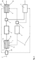
- Fig.1 shows an embodiment of a security control system shown as a block diagram. It provides a baggage drop-off area 1 with one or several delivery stations 1a, 1b, 1c for delivering luggage into a load carrier 2.
- the load carrier 2 loaded with luggage is fed to a baggage inspection station 3 for imaging the luggage, preferably using a computer tomograph.
- the personal screening station 4 preferably has queue and path systems that can specifically control synchronization between baggage status and personal screening. After the personal screening has been completed, the person receives information from an information device 5 as to whether he should go to a baggage collection area 6 with one or more removal stations 6a, 6b, 6c to receive and empty the load carrier assigned to the person or to a follow-up screening area 7 for manual follow-up screening of his baggage.
- the personal paths are in Fig.1 illustrated with solid arrows.
- Dashed arrows show a transport system 8 for transporting the load carriers 2 from the baggage drop-off area 1 via the baggage inspection station 3 to the baggage pick-up area 6 or to the follow-up inspection area 7 and for returning empty load carriers to the baggage drop-off area 1.
- a switch 9 is provided to divert the baggage rejected in the baggage inspection station 3 to the follow-up inspection area 7.
- the operator of the baggage inspection station CT device
- the load carrier 2 is automatically conveyed to the follow-up inspection area 7 so that rejected and non-rejected items of baggage do not become mixed on the route to the baggage pick-up area 6.
- a device 18 is provided for ejecting load carriers 2' that are not completely emptied and/or dirty.
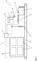
- the baggage drop-off area 1 is described in more detail below using the example of the drop-off station 1a.
- the drop-off station 1a has a first identification device 10 for recording a personal identifier (in particular biometric features) of the person, which is preferably designed as a camera.
- the personal identifier of the person is linked to the load carrier 2 provided at the drop-off station 1a by means of a data processing device 11 in which a marking attached to the load carrier 2 is read out with a reading device (not shown in detail) and linked to the personal identifier of the person.
- the marking on the load carrier 2 can be formed, for example, by an RFID, a QR code or a similar marking.
- a cover 12 opens, which releases the load carrier for loading.
- the load carrier 2 is box-like and open at the top.
- the person can then stow their luggage in the load carrier 2, and visual and/or acoustic instructions can be given to the person via a first information device 13, which in particular comprises a monitor and a loudspeaker.
- a first information device 13 which in particular comprises a monitor and a loudspeaker.
- the load carrier 2 can have a corresponding marking for this purpose.
- the load carrier 2 can be loaded in such a way that the luggage 14 does not protrude beyond the dimensions of the load carrier 2.
- a first monitoring device 15 which is formed by a camera, for example, detects the loading state of the load carrier 2, and in the event of an undesirable loading state, a corresponding indication is given via the first information device 13. Since the luggage 14 in the example shown protrudes beyond the dimensions of the load carrier 2, the person could be asked to insert the luggage correctly or to request a second load carrier. It is also possible to request help from an employee if a person is unable to manage.
- the baggage drop-off process can be completed automatically by a check, in particular after a predetermined time, showing that there is no longer a person at the drop-off station 1a, so that an automated removal of the load carrier 2 can be initiated.
- the person closes the load carrier with a cover or a lid.
- the closure could also be completed by pressing a button or in a similar manner. If the person leaves the removal station without confirmation, they could be prompted to press the button via the first information device 13. If the person nevertheless leaves, which could possibly be prevented by a blockable person exit, an automatic removal can also be initiated after a predetermined time has elapsed.
- the cover 12 first closes and/or a gate 17 opens to allow the load carrier 2 to be removed.
- the load carrier 2 is transported via the transport system 8 and/or a provision system 16 connected to the transport system 8, wherein the first monitoring device 15 is coupled to the provision system 16 and/or the transport system 8 in such a way that the removal of the load carrier 2 from the delivery station 1a is blocked (gate 17 remains closed) if an undesirable loading state of the load carrier 2 is detected.
- the load carrier 2 loaded with luggage is then fed to the baggage inspection station 3 via the transport system 8, while the person goes to the person inspection station 4.
- the delivery station 1a is assigned a buffer area 19 for returned, empty load carriers 2, wherein in the delivery station 1c the next empty load carrier is provided via the transport system 8 or the provision system 16.
- the removal station 6a can basically be constructed similarly or identically to the delivery station 1a.
- the removal station 6a has a second identification device 20 for recording the personal identification of the person standing in front of the removal station 6a, the second identification unit 20 being linked to a second provision system 21 in order to transfer the load carrier 2 linked to the person's personal identification to this removal station 6a.
- the baggage collection area 6 has at least one buffer 22 for several load carriers 2 loaded with baggage, the buffer 22 being assigned to several of the removal stations, for example the removal stations 6a, 6b and 6c.
- the second provision system 21 is designed to transfer the load carriers 2 loaded with luggage from the buffer 22 to one of the removal stations 6a, 6b, 6c, whereby the buffer 22 - regardless of the order in which the load carriers 2 were introduced into the buffer 22 - is able to transfer the load carriers 2 in any order to any of the assigned removal stations.
- the person who wants to collect their luggage can therefore go to any removal station 6a, 6b, 6c that is currently free and is identified there by the second identification device 20, so that the load carrier 2 linked to their personal identifier is transferred from the buffer 22 to this removal station.
- a cover 23 opens, making the load carrier 2 accessible for unloading.
- Information can be provided to the person via an input and/or output unit 24.
- a second monitoring device 25 which is formed by a camera, for example, detects the loading status of the load carrier 2.
- the input and/or output unit 24 can be used to make the person aware, in particular, that there are still pieces of luggage/objects in the load carrier 2. After the load has been completely removed, for example, a good flight can be wished and/or the departure gate can be displayed; it would also be conceivable to display advertising.
- a sensor unit is provided at the existing removal stations, which is formed, for example, by the second identification unit 20, which is designed to determine the presence of a person in front of the removal station, and which is linked to the second monitoring unit 25 and the second provision system 21 in such a way that the emptying process is completed by removing the emptied load carrier 2 if the sensor unit does not detect a person in front of the removal station 6a and the load carrier 2 is empty. In this way, the removal station can be made available to the next person as quickly as possible.
- the cover 23 closes and/or a gate 26 opens to allow the load carrier 2 to be transported away.
- the load carrier 2 is transported via the second provision system 21 and/or the transport system 8, with the second monitoring device 25 being coupled to the second provision system 21 and/or the transport system 8 in such a way that the removal of the load carrier 2 from the removal station 6a is blocked (gate 26 remains closed) if there is still an object in the load carrier 2. If the load carrier 2 is empty, the return transport to the baggage drop-off area 1 is initiated. The next removal process can then be initiated by the next person standing in front of the removal station being detected by the second identification device 20.
- the second monitoring device 25 in the removal stations 6a, 6b, 6c can also be able to detect contamination of the load carrier 2, for example due to a leaked liquid. Contaminated load carriers could then be removed from the device 18 ( Fig.1 ) can be discharged. Discharge could also occur in the case of a load carrier that is not or not completely emptied if the person has left the removal station 6a, 6b, 6c before it is completely emptied.
- the person is first recognized at the information device 5 by means of his or her personal identification and is then informed that he or she must proceed to the subsequent inspection area 7.
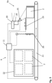
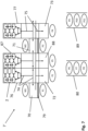
- Fig.4 shows a first embodiment of a post-inspection area 7 according to the invention, which here has a first and a second post-inspection station 70, 71 with a first and a second associated removal station 72, 73 for emptying the load carrier 2 by the person to whom the luggage belongs.
- the post-inspection area 7 also provides a first and a second transfer system 74, 75 for the automated transfer of the load carriers 2 loaded with luggage to the post-inspection stations 70, 71 and from the post-inspection stations 70, 71 to the associated removal stations 72, 73, wherein the transfer systems 74, 75 are designed to transfer the load carriers 2 to the post-inspection station 70 or 71 independently of the occupancy of the associated removal station 72 or 73 with a load carrier 2.
- a load carrier can be transported to the post-inspection location 70 or 71 even if the corresponding removal location 72 or 73 is still occupied.
- a first waiting area M1 or M2 is provided for security check employees, while in front of each collection station 72 or 73, a second waiting area P1 or P3 is provided for people whose luggage needs to be checked, with the size of the first and second waiting areas M1, M2 and P1, P3 being such that at least one person can be there at the same time.
- the post-screening station 70 or 71 is therefore provided between the first waiting area M1 or M2 and the second waiting area P1 or P3.
- the post-inspection area 7 has a first and a second buffer system 76 and 77 for the temporary storage of load carriers 2 loaded with baggage, wherein the transfer systems 74 and 75 are used to transfer the load carriers 2 loaded with baggage temporarily stored in the buffer systems 76 and 77 to the Post-inspection stations 70 and 71 are designed.
- the buffer systems 76, 77 can each provide at least two buffer stations for the temporary storage of load carriers 2 loaded with luggage, the buffer systems 76, 77 being designed to re-sort the load carriers 2 loaded with luggage.
- the first and second buffer systems 76, 77 are each designed for three load carriers 2, although a larger buffer occupancy would also be conceivable.
- the buffer systems 76, 77 are designed to re-sort the load carriers by moving them in at least two different, in particular orthogonal, axial directions, so that the order of the post-inspection is not tied to the order in which the load carriers 2 arrived in one of the buffer systems 76 and 77.
- the people who have to go to the post-inspection area can thus overtake each other and are not tied to the order in which the load carriers arrive in the post-inspection area during the post-inspection.
- the follow-up inspection stations 70, 71 are each equipped with a third identification device 78 for recording the personal identification of the person standing at the follow-up inspection station 70 or 71, the third identification device 78 being linked to the transfer system 74 or 75 in order to transfer the load carrier 2 linked to the person's personal identification to this follow-up inspection station.
- the load carrier 2 with the objectionable baggage is provided between the first and second waiting stations M1, P1, so that the load carrier is located between the employee of the security control system and the person to whom the objectionable baggage belongs.
- a transparent, preferably raising and lowering security partition 79 can be provided between the second waiting station P1 and the provided load carrier 2.
- the post-control area 7 can have at least one waiting area 80 for persons (P5 - P7) until the next post-control place becomes available.
- Each post-control place 70, 71 could optionally provide storage areas to assist with unloading.
- a small X-ray machine or other aids to assist with the follow-up check could be available for the security control system employee. It could also be possible to automatically run the entire load carrier or parts of the luggage through a computer tomograph again at the employee's request.
- the removal station 72 is assigned to the post-inspection station 70 and the removal station 73 is assigned to the post-inspection station 71, wherein the load carriers 2 can be transferred from the buffer 76 and preferably also from the buffer 77 to both post-inspection stations 70, 71.
- an employee of the security control area can be responsible for two post-inspection stations at least temporarily.
- the load carrier with the person's luggage is transferred from the follow-up inspection station 70, 71 to the assigned removal station 72, 73, where it can then be emptied by the person.
- the person then moves from the waiting area P1 to the waiting area P2 in front of the removal station 72 or from the waiting area P3 to the waiting area P4 in front of the removal station 73.
- Fig.6 The collection point is described in more detail using the example of the collection point 72.
- the collection points 72 and 73 of the post-inspection area 7 can be identical or at least very similar to the collection stations 6a, 6b, 6c of the baggage collection area 6.
- the removal station 72 is equipped with an optional fourth identification device 82 for recording the personal identification of the person standing at the removal station 72, wherein the fourth identification device 82 is linked to the first transfer system 74 in order to transfer the load carrier 2 linked to the personal identification of the person from the follow-up inspection station 70 to this removal station 72.
- a further monitoring device 83 is provided for detecting an incompletely emptied and/or dirty load carrier.
- a sensor unit which is formed for example by the fourth identification device 82, is also provided at each removal station 72, which is designed to determine the presence of a person located at the removal station 72 and which is linked to the further monitoring device 83 and the first transfer system 74 in such a way that the emptying process is completed by transporting away the emptied load carrier 2 if the sensor unit does not detect a person in front of the removal station and the load carrier is empty.
- a further information device 84 can be provided in accordance with the removal stations in order to inform the person, for example, about the loading status of the load carrier. This could also be used to display the gate to which the person has to go after emptying the load carrier 2, provided this information is available in the system. Furthermore, a fold-out seat could optionally be provided at the removal station 72, 73, which could make getting dressed easier, for example.
- a cover 85 for releasing the load carrier 2 and a gate 86 can also be present.
- the data processing device 11 is again used to control the process.
- the post-screening area 7 is arranged adjacent to the baggage collection area 6, so that at least one collection point 72 or 73 can function either as a collection point or as a collection station, depending on the number of people in the post-screening area 7 and in the baggage collection area 6.
- Fig.7 shows a second embodiment of a post-inspection area 7', in which a third buffer system 87 and a third removal point 88 are also provided.
- load carriers 2 from the first buffer system 76 as well as from the third buffer system 87 can be provided.
- load carriers 2 from the second buffer system 77 as well as from the third buffer system 87 are preferably provided.
- the load carriers from each of the three buffer systems can be transferred to each of the two post-inspection stations, which would result in the greatest possible flexibility.
- the first waiting area 80 would be completely sufficient.
- the second post-inspection station 71 could, depending on the design of the system, block a transfer of a load carrier 2 from the second buffer system 77 to the first post-inspection station 70 during a post-inspection that is currently taking place, it would be expedient to provide a second waiting area 89 for the persons whose load carriers are brought into the second buffer system 77.
- the information device 5 ( Fig.1 ) not only should the person be informed that he or she must go to the follow-up control area 7', but also be informed which of the two waiting areas 80, 89 is intended for him or her.
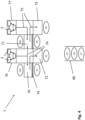
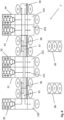
- a third embodiment of a post-control area 7" according to Fig.8
- a total of five buffer systems 90 - 94 with five follow-up inspection stations 95 - 99 and five removal stations 100 - 104 are provided, whereby the special feature is that two follow-up inspection stations 95 and 96 or 97 and 98 are arranged directly next to each other. This has the advantage that one employee could easily operate two follow-up inspection stations if necessary.
- the invention is not limited to the embodiments shown. Rather, other arrangements with more or fewer follow-up inspection stations or removal stations are conceivable. For example, only one large buffer system could be provided that is connected to at least three, preferably all, follow-up inspection stations.
- the return transport of the emptied load carriers 2 can be carried out in a similar manner to the removal stations, in that the first or second transfer system 74, 75 is connected in a suitable manner to the return transport route for the load carriers 2.
Landscapes
- Engineering & Computer Science (AREA)
- Health & Medical Sciences (AREA)
- Physics & Mathematics (AREA)
- General Physics & Mathematics (AREA)
- Mechanical Engineering (AREA)
- Business, Economics & Management (AREA)
- Pathology (AREA)
- Chemical & Material Sciences (AREA)
- Analytical Chemistry (AREA)
- Biochemistry (AREA)
- General Health & Medical Sciences (AREA)
- Immunology (AREA)
- Life Sciences & Earth Sciences (AREA)
- Theoretical Computer Science (AREA)
- Aviation & Aerospace Engineering (AREA)
- Economics (AREA)
- Nuclear Medicine, Radiotherapy & Molecular Imaging (AREA)
- Radiology & Medical Imaging (AREA)
- Pulmonology (AREA)
- Operations Research (AREA)
- Entrepreneurship & Innovation (AREA)
- Human Resources & Organizations (AREA)
- Marketing (AREA)
- Development Economics (AREA)
- Quality & Reliability (AREA)
- Strategic Management (AREA)
- Tourism & Hospitality (AREA)
- General Business, Economics & Management (AREA)
- Analysing Materials By The Use Of Radiation (AREA)
- Warehouses Or Storage Devices (AREA)
Claims (19)
- Système de contrôle de sécurité comprenant :- une zone d'enregistrement des bagages (1) comprenant au moins une station de dépôt (1a, 1b, 1c) et servant à l'enregistrement des bagages d'une personne dans au moins un support de charge (2),- une station de contrôle des bagages (3) pour l'examen par imagerie des bagages,- une zone de récupération des bagages (6) pour des bagages non contestés dans la station de contrôle des bagages,- une zone de contrôle de suivi (7) comprenant au moins un emplacement de contrôle de suivi (70, 71) accessible de deux côtés et servant au contrôle de suivi manuel, par un personnel de sécurité, pour des bagages contestés dans la station de contrôle des bagages, ledit contrôle de suivi ayant lieu en présence de la personne à qui les bagages appartiennent,- un système de transport (8) conçu pour le transport des supports de charge (2) chargés de bagages, ledit transport étant effectué à partir de la zone d'enregistrement des bagages (1) jusqu'à la zone de récupération des bagages (6) en passant par la station de contrôle des bagages (3), ou bien effectué jusqu'à la zone de contrôle de suivi (7), ledit système de transport étant conçu également pour le transport de retour de supports de charge vides (2) jusqu'à la zone d'enregistrement des bagages (1), où :- la zone de contrôle de suivi (7) présente au moins un emplacement d'enlèvement (72, 73) affecté à l'emplacement de contrôle de suivi (70, 71) pour le déchargement du support de charge (2) par la personne à qui les bagages appartiennent,- la zone de contrôle de suivi (7) présente au moins un système de transfert (74, 75) servant au transfert automatisé du support de charge (2) chargé de bagages, ledit transfert étant effectué jusqu'à l'emplacement de contrôle de suivi (70, 71) et depuis l'emplacement de contrôle de suivi (70, 71) jusqu'à l'emplacement d'enlèvement associé (72, 73), où le système de transfert (74, 75) servant au transfert automatisé d'un support de charge (2) jusqu'à l'emplacement de contrôle de suivi (70, 71) est configuré indépendamment du fait que l'emplacement d'enlèvement associé (72, 73) est occupé par un support de charge (2).
- Système de contrôle de sécurité selon la revendication 1, où, devant l'emplacement de contrôle de suivi (70, 71), il y a une première zone d'arrêt (P1, P3) et, devant l'emplacement d'enlèvement (72, 73), il y a une deuxième zone d'arrêt (P2, P4) pour des personnes, où la taille de la première et de la deuxième zone d'arrêt (P1 - P4) est dimensionnée de manière telle, qu'au moins une personne puisse à chaque fois s'y trouver en même temps.
- système de contrôle de sécurité selon la revendication 1, où la zone de contrôle de suivi (7) présente au moins un système de tampons (76, 77 ; 87) servant au stockage temporaire de supports de charge (2) chargés de bagages, et le système de transfert (74, 75) est conçu pour le transfert, jusqu'à l'emplacement de contrôle de suivi (70, 71), des supports de charge (2) chargés de bagages et stockés de façon temporaire dans le système de tampons (76, 77 ; 87).
- Système de contrôle de sécurité selon la revendication 3, où le système de tampons (76, 77 ; 87) présente au moins deux espaces tampons servant au stockage temporaire de supports de charge (2) chargés de bagages, et le système de tampons (76, 77 ; 87) est conçu pour retrier les supports de charge (2) chargés de bagages.
- système de contrôle de sécurité selon la revendication 3, où le système de tampons (76, 77 ; 87) est conçu pour retrier les supports de charge (2) par déplacement dans au moins deux directions axiales - en particulier orthogonales - différentes.
- système de contrôle de sécurité selon la revendication 1, où il est prévu dans la zone d'enregistrement des bagages (1), à chaque station de dépôt (1a, 1b, 1c), un premier dispositif d'identification (10) servant à détecter un identifiant personnel de la personne, premier dispositif d'identification qui agit de façon conjointe avec un système de traitement de données (11) servant à la liaison de l'identifiant personnel de la personne avec le support de charge (2) dans lequel se trouvent les bagages de la personne.
- Système de contrôle de sécurité selon la revendication 6, où l'au moins un emplacement de contrôle de suivi (70, 71) est doté d'un troisième dispositif d'identification (78) servant à détecter l'identifiant personnel de la personne qui se trouve à l'emplacement de contrôle de suivi (70, 71), où le troisième dispositif d'identification (78) est combiné avec le système de transfert (74, 75), afin de transférer, jusqu'à cet emplacement de contrôle de suivi (70, 71), le support de charge (2) lié à l'identifiant personnel de la personne.
- système de contrôle de sécurité selon la revendication 3, où la zone de contrôle de suivi (7) présente au moins deux emplacements de contrôle de suivi (70, 71) dotés à chaque fois d'au moins un emplacement d'enlèvement associé (72, 73), et le système de transfert (74, 75) est conçu pour le transfert de supports de charge (2) chargés de bagages, ledit transfert étant effectué depuis le système de tampons (76, 77 ; 87) jusqu'aux au moins deux emplacements de contrôle de suivi (70, 71).
- système de contrôle de sécurité selon la revendication 2, où l'emplacement de contrôle de suivi (70, 71) servant à la mise à disposition du support de charge (2), avec les bagages contestés, est disposé entre le premier et le deuxième emplacement d'arrêt (M1, P1 ; M2, P3), et il est prévu en outre une cloison de séparation transparente (79) placée entre le support de charge (2) mis à disposition et le deuxième emplacement d'arrêt (M1, P1 ; M2, P3).
- Système de contrôle de sécurité selon la revendication 1, où la zone de contrôle de suivi (7) présente au moins une zone d'attente (80) pour des personnes dont les bagages ont été contestés dans la station de contrôle des bagages (3).
- Système de contrôle de sécurité selon la revendication 1, où il est prévu, à chaque emplacement d'enlèvement (72, 73), au moins un dispositif de surveillance (83) servant à détecter un support de charge (2) non complètement vidé et/ou encrassé.
- Système de contrôle de sécurité selon la revendication 1, où il est prévu, à chaque emplacement d'enlèvement, des unités d'entrée et/ou de sortie qui sont conçues pour la mise à disposition d'informations à la personne et/ou pour l'achèvement du processus de déchargement du support de charge par la personne.
- Système de contrôle de sécurité selon la revendication 1, où il est prévu, à chaque emplacement d'enlèvement (72, 73), une unité de capteur qui est formée par exemple par le quatrième dispositif d'identification (82), unité de capteur qui est conçue pour constater la présence d'une personne se trouvant à l'emplacement d'enlèvement (72, 73) et qui est combinée avec le dispositif de surveillance (83) et avec le système de transfert (74, 75), de manière telle que le processus de déchargement soit achevé par l'évacuation du support de charge vidé (2), si l'unité de capteur ne détecte aucune personne devant l'emplacement d'enlèvement (72, 73) et si le support de charge est vide.
- Système de contrôle de sécurité selon la revendication 1, où la zone de contrôle de suivi (7) est disposée de façon adjacente à la zone de récupération des bagages (6), et au moins un emplacement d'enlèvement (72, 73) - en fonction du nombre de personnes se trouvant dans la zone de contrôle de suivi (7) et dans la zone de récupération des bagages (6) - fonctionne comme emplacement d'enlèvement (72, 73) ou comme station d'enlèvement (6a, 6b, 6c).
- Procédé de contrôle de sécurité, où :- une personne, qui se trouve dans une zone d'enregistrement des bagages (1) comprenant une ou plusieurs stations de dépôt (1a, 1b, 1c), enregistre ses bagages dans un support de charge (2) mis à disposition dans une station de dépôt (1a, 1b, 1c),- les bagages se trouvant dans une station de contrôle des bagages (3) sont soumis à un examen par imagerie,- la personne récupère ses bagages dans une zone de récupération des bagages (6), dans la mesure où les bagages n'ont pas été contestés dans la station de contrôle des bagages,- pour le contrôle de suivi manuel, la personne se rend dans une zone de contrôle de suivi (7) comprenant au moins un emplacement de contrôle de suivi (70, 71) accessible de deux côtés, dans la mesure où les bagages ont été contestés dans la station de contrôle des bagages (3), où l'emplacement de contrôle de suivi (70, 71) est accessible, sur un côté, par un employé du système de contrôle de sécurité et, sur l'autre côté, accessible par la personne à qui appartiennent les bagages contestés,- les supports de charge (2) chargés de bagages sont transportés à partir de la zone d'enregistrement des bagages (1) jusqu'à la zone de récupération des bagages (6) en passant par la station de contrôle des bagages (3), ou bien transportés jusqu'à la zone de contrôle de suivi (7), et des supports de charge vides (2) sont retransportés jusqu'à la zone d'enregistrement des bagages (1),- après le contrôle manuel des bagages, la personne se rend, en partant de l'emplacement de contrôle de suivi (70, 71), jusqu'à un emplacement d'enlèvement associé (72, 73) pour le déchargement du support de charge (2),- le support de charge (2) chargé de bagages de la personne est transféré de manière automatisée depuis l'emplacement de contrôle de suivi (70, 71) jusqu'à l'emplacement d'enlèvement associé (72, 73), où le transfert automatisé d'un nouveau support de charge (2) chargé de bagages est effectué jusqu'à l'emplacement de contrôle de suivi (70, 71), indépendamment du fait que l'emplacement d'enlèvement associé (72, 73) est occupé par un support de charge (2).
- Procédé de contrôle de sécurité selon la revendication 15, où, à chaque station de dépôt (1a, 1b, 1c), un identifiant personnel de la personne est détecté au moyen d'un premier dispositif d'identification (10), et l'identifiant personnel de la personne, au moyen d'un dispositif de traitement de données (11), est lié au support de charge (2) dans lequel se trouvent les bagages de la personne.
- Procédé de contrôle de sécurité selon la revendication 16, où, à chaque emplacement de contrôle de suivi (70, 71), l'identifiant personnel de la personne est détecté au moyen d'un troisième dispositif d'identification (78) et, à la suite de quoi, le support de charge (2) lié à la personne est mis à disposition à l'emplacement de contrôle de suivi (70, 71).
- Procédé de contrôle de sécurité selon la revendication 17, où, à chaque emplacement d'enlèvement (72, 73), l'identifiant personnel de la personne est détecté au moyen d'un quatrième dispositif d'identification (82), et le support de charge (2) lié à la personne est transféré depuis l'emplacement de contrôle de suivi (70, 71) jusqu'à l'emplacement d'enlèvement (72, 73).
- Procédé de contrôle de sécurité selon la revendication 18, où le processus de déchargement du support de charge (2) se produisant à l'emplacement d'enlèvement (72, 73) est achevé de manière automatisée et le support de charge (2) est évacué, tandis qu'une unité de surveillance (83) détecte un support de charge vide (2), et une unité de capteur, qui est formée, constate qu'aucune personne ne se trouve à l'emplacement d'enlèvement (72, 73).
Applications Claiming Priority (2)
| Application Number | Priority Date | Filing Date | Title |
|---|---|---|---|
| DE102021129502.5A DE102021129502A1 (de) | 2021-11-12 | 2021-11-12 | Sicherheitskontrollsystem und Sicherheitskontrollverfahren |
| PCT/EP2022/081613 WO2023084017A1 (fr) | 2021-11-12 | 2022-11-11 | Système de contrôle de sécurité et procédé de contrôle de sécurité |
Publications (3)
| Publication Number | Publication Date |
|---|---|
| EP4264523A1 EP4264523A1 (fr) | 2023-10-25 |
| EP4264523B1 true EP4264523B1 (fr) | 2024-07-31 |
| EP4264523C0 EP4264523C0 (fr) | 2024-07-31 |
Family
ID=84367444
Family Applications (1)
| Application Number | Title | Priority Date | Filing Date |
|---|---|---|---|
| EP22814424.2A Active EP4264523B1 (fr) | 2021-11-12 | 2022-11-11 | Système de contrôle de sécurité et procédé de contrôle de sécurité |
Country Status (8)
| Country | Link |
|---|---|
| US (1) | US20250052702A1 (fr) |
| EP (1) | EP4264523B1 (fr) |
| JP (1) | JP7829956B2 (fr) |
| AU (1) | AU2022388776A1 (fr) |
| DE (1) | DE102021129502A1 (fr) |
| ES (1) | ES2985519T3 (fr) |
| PL (1) | PL4264523T3 (fr) |
| WO (1) | WO2023084017A1 (fr) |
Families Citing this family (1)
| Publication number | Priority date | Publication date | Assignee | Title |
|---|---|---|---|---|
| CN116895115B (zh) * | 2023-09-11 | 2023-12-05 | 今创集团股份有限公司 | 车站液体自助复检机、复检控制软件系统及自助复检方法 |
Family Cites Families (10)
| Publication number | Priority date | Publication date | Assignee | Title |
|---|---|---|---|---|
| JP2002257751A (ja) * | 2001-03-01 | 2002-09-11 | Kawasaki Heavy Ind Ltd | 手荷物検査方法および手荷物検査システム |
| NL2005893C2 (nl) | 2010-12-22 | 2012-06-25 | Vanderlande Ind Bv | Systeem en werkwijze voor het bufferen van bagagestukken. |
| US9047714B2 (en) | 2011-03-10 | 2015-06-02 | Siemens Industry, Inc. | Automated passenger screening checkpoint |
| CN104502368B (zh) * | 2014-12-29 | 2018-11-23 | 同方威视技术股份有限公司 | 一体化安全检查系统 |
| CN106548263A (zh) * | 2015-09-21 | 2017-03-29 | 同方威视技术股份有限公司 | 一种智能安全检查系统和方法 |
| JP6427513B2 (ja) * | 2016-02-03 | 2018-11-21 | 三協立山株式会社 | カウンター |
| JP6674342B2 (ja) * | 2016-06-30 | 2020-04-01 | 株式会社日立製作所 | 検査システムおよび入場管理設備 |
| US11443576B2 (en) | 2019-06-11 | 2022-09-13 | Flughafen Wien Aktiengesellschaft | System and method for baggage control |
| CN111426704B (zh) * | 2020-01-06 | 2023-06-09 | 航科院(北京)科技发展有限公司 | 一种行李安检系统及方法 |
| CN220195588U (zh) * | 2022-11-06 | 2023-12-19 | 中国铁路兰州局集团有限公司 | 智能安检配套筛选传送机 |
-
2021
- 2021-11-12 DE DE102021129502.5A patent/DE102021129502A1/de active Pending
-
2022
- 2022-11-11 JP JP2024527747A patent/JP7829956B2/ja active Active
- 2022-11-11 US US18/709,101 patent/US20250052702A1/en active Pending
- 2022-11-11 PL PL22814424.2T patent/PL4264523T3/pl unknown
- 2022-11-11 AU AU2022388776A patent/AU2022388776A1/en not_active Abandoned
- 2022-11-11 EP EP22814424.2A patent/EP4264523B1/fr active Active
- 2022-11-11 ES ES22814424T patent/ES2985519T3/es active Active
- 2022-11-11 WO PCT/EP2022/081613 patent/WO2023084017A1/fr not_active Ceased
Also Published As
| Publication number | Publication date |
|---|---|
| JP7829956B2 (ja) | 2026-03-16 |
| PL4264523T3 (pl) | 2024-09-30 |
| US20250052702A1 (en) | 2025-02-13 |
| EP4264523C0 (fr) | 2024-07-31 |
| JP2024546434A (ja) | 2024-12-24 |
| WO2023084017A1 (fr) | 2023-05-19 |
| DE102021129502A1 (de) | 2023-05-17 |
| AU2022388776A1 (en) | 2024-06-20 |
| ES2985519T3 (es) | 2024-11-06 |
| EP4264523A1 (fr) | 2023-10-25 |
Similar Documents
| Publication | Publication Date | Title |
|---|---|---|
| DE69630938T2 (de) | Verfahren und System zum Empfangen und Handhaben von Gepäck in Flughäfen sowie automatisches Gerät zum Handhaben von Gepäck | |
| DE102012013247B4 (de) | Vorrichtung zur Gepäckannahme und Verfahren zum Betrieb einer solchen Vorrichtung | |
| EP2174274B1 (fr) | Procédé d'identification de biens transportés, notamment de bagages | |
| EP3009993B1 (fr) | Procédé et dispositif d'augmentation de la sécurité dans une zone d'accès et d'optimisation de l'utilisation de la capacité dans des moyens de transport présentant au moins une zone d'accès définie localement | |
| DE102010005267A1 (de) | Fördereinrichtung für Stückgut, Aufsatzvorrichtung für eine Fördereinrichtung, Stückgutverteilanlage und Verfahren zum Einbringen von Stückgut in eine Stückgutverteilanlage | |
| EP3942535B1 (fr) | Système et procédé de contrôle de bagages | |
| DE1406112A1 (de) | UEberwachungseinrichtung an Foerderanlagen | |
| EP4264523B1 (fr) | Système de contrôle de sécurité et procédé de contrôle de sécurité | |
| EP4263356B1 (fr) | Système et procédé d'inspection de sécurité | |
| EP4255809B1 (fr) | Système de commande de sécurité et procédé de commande de sécurité | |
| DE10156038A1 (de) | Verfahren zur Sicherung des Luftverkehrs | |
| DE102019212620A1 (de) | Aufbewahrung von Gegenständen innerhalb eines Fahrzeugs | |
| EP3630613B1 (fr) | Dispositif de transport | |
| EP3169589B1 (fr) | Dispositif, guichet et procédé de depose des bagages | |
| DE102009022665A1 (de) | Gepäckinformationssystem an einem Gepäckausgabeband | |
| EP2919199B1 (fr) | Procédé et système de contrôle d'autorisation d'accès pour des moyens de transport roulant en cadence et présentant au moins une zone de montée fixée dans l'espace et au moins une zone de descente fixée dans l'espace | |
| EP4131188A1 (fr) | Écluse, système comprenant une écluse, procédé de commande d'un flux de personnes et/ou de contrôle de personnes, produit-programme informatique | |
| DE102019134864A1 (de) | System und Verfahren zum Steuern einer Warteschlange zum Eintreten in ein Verkehrsmittel | |
| EP3298439B1 (fr) | Correction d'images de rayons x | |
| EP1636984B1 (fr) | Systeme de detection d'objets avec des moyens de transport pour les objets et avec un capteur d'image | |
| DE19725323A1 (de) | Flughafenzubringer | |
| DE102023101826A1 (de) | Aufzugsvorrichtung mit akustischer Haltepositionsinformationsausgabe sowie entsprechendes Ausgabeverfahren und Verwendung | |
| DE102021210632A1 (de) | Warenschleuse für ein Kraftfahrzeug, Warenschleusenanordnung und Kraftfahrzeug |
Legal Events
| Date | Code | Title | Description |
|---|---|---|---|
| STAA | Information on the status of an ep patent application or granted ep patent |
Free format text: STATUS: UNKNOWN |
|
| STAA | Information on the status of an ep patent application or granted ep patent |
Free format text: STATUS: THE INTERNATIONAL PUBLICATION HAS BEEN MADE |
|
| PUAI | Public reference made under article 153(3) epc to a published international application that has entered the european phase |
Free format text: ORIGINAL CODE: 0009012 |
|
| STAA | Information on the status of an ep patent application or granted ep patent |
Free format text: STATUS: REQUEST FOR EXAMINATION WAS MADE |
|
| 17P | Request for examination filed |
Effective date: 20230717 |
|
| AK | Designated contracting states |
Kind code of ref document: A1 Designated state(s): AL AT BE BG CH CY CZ DE DK EE ES FI FR GB GR HR HU IE IS IT LI LT LU LV MC ME MK MT NL NO PL PT RO RS SE SI SK SM TR |
|
| STAA | Information on the status of an ep patent application or granted ep patent |
Free format text: STATUS: EXAMINATION IS IN PROGRESS |
|
| 17Q | First examination report despatched |
Effective date: 20240103 |
|
| GRAP | Despatch of communication of intention to grant a patent |
Free format text: ORIGINAL CODE: EPIDOSNIGR1 |
|
| STAA | Information on the status of an ep patent application or granted ep patent |
Free format text: STATUS: GRANT OF PATENT IS INTENDED |
|
| DAV | Request for validation of the european patent (deleted) | ||
| DAX | Request for extension of the european patent (deleted) | ||
| INTG | Intention to grant announced |
Effective date: 20240517 |
|
| GRAS | Grant fee paid |
Free format text: ORIGINAL CODE: EPIDOSNIGR3 |
|
| GRAA | (expected) grant |
Free format text: ORIGINAL CODE: 0009210 |
|
| STAA | Information on the status of an ep patent application or granted ep patent |
Free format text: STATUS: THE PATENT HAS BEEN GRANTED |
|
| AK | Designated contracting states |
Kind code of ref document: B1 Designated state(s): AL AT BE BG CH CY CZ DE DK EE ES FI FR GB GR HR HU IE IS IT LI LT LU LV MC ME MK MT NL NO PL PT RO RS SE SI SK SM TR |
|
| REG | Reference to a national code |
Ref country code: CH Ref legal event code: EP Ref country code: GB Ref legal event code: FG4D Free format text: NOT ENGLISH |
|
| REG | Reference to a national code |
Ref country code: DE Ref legal event code: R096 Ref document number: 502022001369 Country of ref document: DE |
|
| REG | Reference to a national code |
Ref country code: IE Ref legal event code: FG4D Free format text: LANGUAGE OF EP DOCUMENT: GERMAN |
|
| U01 | Request for unitary effect filed |
Effective date: 20240731 |
|
| U07 | Unitary effect registered |
Designated state(s): AT BE BG DE DK EE FI FR IT LT LU LV MT NL PT SE SI Effective date: 20240807 |
|
| REG | Reference to a national code |
Ref country code: ES Ref legal event code: FG2A Ref document number: 2985519 Country of ref document: ES Kind code of ref document: T3 Effective date: 20241106 |
|
| U20 | Renewal fee for the european patent with unitary effect paid |
Year of fee payment: 3 Effective date: 20241105 |
|
| PG25 | Lapsed in a contracting state [announced via postgrant information from national office to epo] |
Ref country code: NO Free format text: LAPSE BECAUSE OF FAILURE TO SUBMIT A TRANSLATION OF THE DESCRIPTION OR TO PAY THE FEE WITHIN THE PRESCRIBED TIME-LIMIT Effective date: 20241031 |
|
| PG25 | Lapsed in a contracting state [announced via postgrant information from national office to epo] |
Ref country code: GR Free format text: LAPSE BECAUSE OF FAILURE TO SUBMIT A TRANSLATION OF THE DESCRIPTION OR TO PAY THE FEE WITHIN THE PRESCRIBED TIME-LIMIT Effective date: 20241101 |
|
| PG25 | Lapsed in a contracting state [announced via postgrant information from national office to epo] |
Ref country code: IS Free format text: LAPSE BECAUSE OF FAILURE TO SUBMIT A TRANSLATION OF THE DESCRIPTION OR TO PAY THE FEE WITHIN THE PRESCRIBED TIME-LIMIT Effective date: 20241130 |
|
| PG25 | Lapsed in a contracting state [announced via postgrant information from national office to epo] |
Ref country code: HR Free format text: LAPSE BECAUSE OF FAILURE TO SUBMIT A TRANSLATION OF THE DESCRIPTION OR TO PAY THE FEE WITHIN THE PRESCRIBED TIME-LIMIT Effective date: 20240731 |
|
| PG25 | Lapsed in a contracting state [announced via postgrant information from national office to epo] |
Ref country code: RS Free format text: LAPSE BECAUSE OF FAILURE TO SUBMIT A TRANSLATION OF THE DESCRIPTION OR TO PAY THE FEE WITHIN THE PRESCRIBED TIME-LIMIT Effective date: 20241031 |
|
| PG25 | Lapsed in a contracting state [announced via postgrant information from national office to epo] |
Ref country code: RS Free format text: LAPSE BECAUSE OF FAILURE TO SUBMIT A TRANSLATION OF THE DESCRIPTION OR TO PAY THE FEE WITHIN THE PRESCRIBED TIME-LIMIT Effective date: 20241031 Ref country code: NO Free format text: LAPSE BECAUSE OF FAILURE TO SUBMIT A TRANSLATION OF THE DESCRIPTION OR TO PAY THE FEE WITHIN THE PRESCRIBED TIME-LIMIT Effective date: 20241031 Ref country code: IS Free format text: LAPSE BECAUSE OF FAILURE TO SUBMIT A TRANSLATION OF THE DESCRIPTION OR TO PAY THE FEE WITHIN THE PRESCRIBED TIME-LIMIT Effective date: 20241130 Ref country code: HR Free format text: LAPSE BECAUSE OF FAILURE TO SUBMIT A TRANSLATION OF THE DESCRIPTION OR TO PAY THE FEE WITHIN THE PRESCRIBED TIME-LIMIT Effective date: 20240731 Ref country code: GR Free format text: LAPSE BECAUSE OF FAILURE TO SUBMIT A TRANSLATION OF THE DESCRIPTION OR TO PAY THE FEE WITHIN THE PRESCRIBED TIME-LIMIT Effective date: 20241101 |
|
| PG25 | Lapsed in a contracting state [announced via postgrant information from national office to epo] |
Ref country code: SM Free format text: LAPSE BECAUSE OF FAILURE TO SUBMIT A TRANSLATION OF THE DESCRIPTION OR TO PAY THE FEE WITHIN THE PRESCRIBED TIME-LIMIT Effective date: 20240731 |
|
| PG25 | Lapsed in a contracting state [announced via postgrant information from national office to epo] |
Ref country code: CZ Free format text: LAPSE BECAUSE OF FAILURE TO SUBMIT A TRANSLATION OF THE DESCRIPTION OR TO PAY THE FEE WITHIN THE PRESCRIBED TIME-LIMIT Effective date: 20240731 |
|
| PG25 | Lapsed in a contracting state [announced via postgrant information from national office to epo] |
Ref country code: SK Free format text: LAPSE BECAUSE OF FAILURE TO SUBMIT A TRANSLATION OF THE DESCRIPTION OR TO PAY THE FEE WITHIN THE PRESCRIBED TIME-LIMIT Effective date: 20240731 |
|
| PLBE | No opposition filed within time limit |
Free format text: ORIGINAL CODE: 0009261 |
|
| STAA | Information on the status of an ep patent application or granted ep patent |
Free format text: STATUS: NO OPPOSITION FILED WITHIN TIME LIMIT |
|
| PG25 | Lapsed in a contracting state [announced via postgrant information from national office to epo] |
Ref country code: MC Free format text: LAPSE BECAUSE OF FAILURE TO SUBMIT A TRANSLATION OF THE DESCRIPTION OR TO PAY THE FEE WITHIN THE PRESCRIBED TIME-LIMIT Effective date: 20240731 |
|
| 26N | No opposition filed |
Effective date: 20250501 |
|
| PG25 | Lapsed in a contracting state [announced via postgrant information from national office to epo] |
Ref country code: IE Free format text: LAPSE BECAUSE OF NON-PAYMENT OF DUE FEES Effective date: 20241111 |
|
| PG25 | Lapsed in a contracting state [announced via postgrant information from national office to epo] |
Ref country code: RO Free format text: LAPSE BECAUSE OF FAILURE TO SUBMIT A TRANSLATION OF THE DESCRIPTION OR TO PAY THE FEE WITHIN THE PRESCRIBED TIME-LIMIT Effective date: 20240731 |
|
| U20 | Renewal fee for the european patent with unitary effect paid |
Year of fee payment: 4 Effective date: 20251103 |
|
| PGFP | Annual fee paid to national office [announced via postgrant information from national office to epo] |
Ref country code: PL Payment date: 20251024 Year of fee payment: 4 |
|
| PGFP | Annual fee paid to national office [announced via postgrant information from national office to epo] |
Ref country code: ES Payment date: 20251229 Year of fee payment: 4 |
|
| PG25 | Lapsed in a contracting state [announced via postgrant information from national office to epo] |
Ref country code: HU Free format text: LAPSE BECAUSE OF FAILURE TO SUBMIT A TRANSLATION OF THE DESCRIPTION OR TO PAY THE FEE WITHIN THE PRESCRIBED TIME-LIMIT; INVALID AB INITIO Effective date: 20221111 |
|
| PG25 | Lapsed in a contracting state [announced via postgrant information from national office to epo] |
Ref country code: CY Free format text: LAPSE BECAUSE OF FAILURE TO SUBMIT A TRANSLATION OF THE DESCRIPTION OR TO PAY THE FEE WITHIN THE PRESCRIBED TIME-LIMIT; INVALID AB INITIO Effective date: 20221111 |