EP4265131A1 - Dispositif de génération et de filtration de fumée et e-narguilé - Google Patents
Dispositif de génération et de filtration de fumée et e-narguilé Download PDFInfo
- Publication number
- EP4265131A1 EP4265131A1 EP21905713.0A EP21905713A EP4265131A1 EP 4265131 A1 EP4265131 A1 EP 4265131A1 EP 21905713 A EP21905713 A EP 21905713A EP 4265131 A1 EP4265131 A1 EP 4265131A1
- Authority
- EP
- European Patent Office
- Prior art keywords
- smoke
- filtration
- component
- heating
- chamber
- Prior art date
- Legal status (The legal status is an assumption and is not a legal conclusion. Google has not performed a legal analysis and makes no representation as to the accuracy of the status listed.)
- Pending
Links
- 239000000779 smoke Substances 0.000 title claims abstract description 337
- 238000001914 filtration Methods 0.000 title claims abstract description 162
- 238000010438 heat treatment Methods 0.000 claims abstract description 162
- XLYOFNOQVPJJNP-UHFFFAOYSA-N water Substances O XLYOFNOQVPJJNP-UHFFFAOYSA-N 0.000 claims abstract description 20
- 239000000463 material Substances 0.000 claims abstract description 16
- 241000208125 Nicotiana Species 0.000 claims abstract description 14
- 235000002637 Nicotiana tabacum Nutrition 0.000 claims abstract description 14
- 239000002184 metal Substances 0.000 claims description 51
- 230000006698 induction Effects 0.000 claims description 32
- 238000010992 reflux Methods 0.000 claims description 28
- 238000002955 isolation Methods 0.000 claims description 13
- 239000000919 ceramic Substances 0.000 claims description 10
- VYPSYNLAJGMNEJ-UHFFFAOYSA-N silicon dioxide Inorganic materials O=[Si]=O VYPSYNLAJGMNEJ-UHFFFAOYSA-N 0.000 claims description 9
- 239000011521 glass Substances 0.000 claims description 8
- 239000013078 crystal Substances 0.000 claims description 6
- 239000010453 quartz Substances 0.000 claims description 6
- 239000003053 toxin Substances 0.000 claims description 5
- 231100000765 toxin Toxicity 0.000 claims description 5
- 108700012359 toxins Proteins 0.000 claims description 5
- 239000000126 substance Substances 0.000 abstract description 6
- 238000004140 cleaning Methods 0.000 abstract description 3
- 239000003571 electronic cigarette Substances 0.000 abstract description 2
- 230000000391 smoking effect Effects 0.000 description 5
- 238000009434 installation Methods 0.000 description 3
- 230000003670 easy-to-clean Effects 0.000 description 2
- 238000012986 modification Methods 0.000 description 2
- 230000004048 modification Effects 0.000 description 2
- 235000019645 odor Nutrition 0.000 description 2
- 238000004090 dissolution Methods 0.000 description 1
- 229910001220 stainless steel Inorganic materials 0.000 description 1
- 239000010935 stainless steel Substances 0.000 description 1
Images






Classifications
-
- A—HUMAN NECESSITIES
- A24—TOBACCO; CIGARS; CIGARETTES; SIMULATED SMOKING DEVICES; SMOKERS' REQUISITES
- A24F—SMOKERS' REQUISITES; MATCH BOXES; SIMULATED SMOKING DEVICES
- A24F1/00—Tobacco pipes
- A24F1/30—Hookahs
-
- A—HUMAN NECESSITIES
- A24—TOBACCO; CIGARS; CIGARETTES; SIMULATED SMOKING DEVICES; SMOKERS' REQUISITES
- A24F—SMOKERS' REQUISITES; MATCH BOXES; SIMULATED SMOKING DEVICES
- A24F1/00—Tobacco pipes
- A24F1/02—Tobacco pipes with arrangements for cleaning or cooling the smoke
- A24F1/04—Tobacco pipes with arrangements for cleaning or cooling the smoke with smoke chamber or slobber traps
- A24F1/06—Tobacco pipes with arrangements for cleaning or cooling the smoke with smoke chamber or slobber traps inside the pipe
-
- A—HUMAN NECESSITIES
- A24—TOBACCO; CIGARS; CIGARETTES; SIMULATED SMOKING DEVICES; SMOKERS' REQUISITES
- A24F—SMOKERS' REQUISITES; MATCH BOXES; SIMULATED SMOKING DEVICES
- A24F40/00—Electrically operated smoking devices; Component parts thereof; Manufacture thereof; Maintenance or testing thereof; Charging means specially adapted therefor
- A24F40/40—Constructional details, e.g. connection of cartridges and battery parts
- A24F40/46—Shape or structure of electric heating means
- A24F40/465—Shape or structure of electric heating means specially adapted for induction heating
-
- A—HUMAN NECESSITIES
- A24—TOBACCO; CIGARS; CIGARETTES; SIMULATED SMOKING DEVICES; SMOKERS' REQUISITES
- A24F—SMOKERS' REQUISITES; MATCH BOXES; SIMULATED SMOKING DEVICES
- A24F40/00—Electrically operated smoking devices; Component parts thereof; Manufacture thereof; Maintenance or testing thereof; Charging means specially adapted therefor
- A24F40/20—Devices using solid inhalable precursors
-
- A—HUMAN NECESSITIES
- A24—TOBACCO; CIGARS; CIGARETTES; SIMULATED SMOKING DEVICES; SMOKERS' REQUISITES
- A24F—SMOKERS' REQUISITES; MATCH BOXES; SIMULATED SMOKING DEVICES
- A24F40/00—Electrically operated smoking devices; Component parts thereof; Manufacture thereof; Maintenance or testing thereof; Charging means specially adapted therefor
- A24F40/40—Constructional details, e.g. connection of cartridges and battery parts
- A24F40/48—Fluid transfer means, e.g. pumps
- A24F40/485—Valves; Apertures
Definitions
- the disclosure relates to the field of electronic cigarettes, and more particularly, to a smoke generation and filtration device, and a hookah comprising the same.
- a conventional hookah includes a smoke generation and filtration device.
- the smoke generation and filtration device typically includes a heating component and a smoke filtration component.
- the smoke filtration component is configured to filter out the toxins from the smoke.
- the heating component heats the tobacco material to generate smoke.
- the smoke is then passed through the smoke filtration component, discharged to a contact part, and ultimately inhaled by users.
- the heating component are usually located on the side or top of the smoke filtration component, resulting in excessive lateral dimensions of the smoke generation and filtration device. This is inconvenient for users in holding the smoke generation and filtering component while smoking. Moreover, the smoke enters the smoke filtration device from the side or top, leading to insufficient dissolution of harmful substances in the water.
- the conventional hookahs are typically integrally formed, making it difficult to clean the smoke generation and filtration device.
- the smoke generation and filtration device cannot be detached from the main body of the hookah, resulting in inconvenience in terms of usability and portability.
- replacing individual components is also inconvenient.
- the first objective of the disclosure is to provide a smoke generation and filtration device, to solve the technical problems of inconvenient handheld state and poor effectiveness in dissolving harmful substances in water of existing smoke generation and filtration devices.
- a second objective of the disclosure is to provide a hookah.
- the smoke generation and filtration device comprises:
- the smoke filtration component comprises a smoke filtration chamber, a first smoke guide channel, and a second smoke guide channel;
- the first smoke guide channel comprises a first smoke inlet channel and a reflux channel
- the smoke filtration component comprises an outer tube and an isolation plate; the isolation plate comprises a first communication hole; and the isolation plate is radially connected to the inner wall of the outer tube, to separate the inner cavity of the outer tube into a first cavity and a second cavity; the heating component is disposed inside the first cavity and extends out of the first cavity; the smoke filtration chamber, the first smoke guide channel, and the second smoke guide channel are disposed in the second cavity; and the heating component is connected to the first smoke guide channel via the first communication hole.
- the smoke filtration component comprises glass, quartz or crystal.
- the heating component comprises a second smoke inlet channel connected to the smoke filtration component; the generated smoke flows through the second smoke inlet channel and enters the smoke filtration component.
- the heating component comprises a heating body and a metal heating unit
- the heating body comprises a connecting portion and a heating portion connected to the connecting portion; and the connecting portion is detachably connected to the first end of the smoke filtration component; the heating portion extends outward from the connecting portion and is away from the second end of the smoke filtration component; the heating portion is disposed in an induction coil disposed outside the smoke generation and filtration device; and both the metal heating unit and the second communication hole are disposed on the heating portion.
- the heating body comprises glass, quartz, agate, or crystal.
- the heating component comprises a connecting pipe and a metal container for holding the tobacco material; the metal container is detachably connected to the connecting pipe and is disposed inside the induction coil; the induction coil is independent from the smoke generation and filtration device; and the connecting pipe comprises an inner cavity communicating with the second smoke inlet channel; the metal container comprises a third communication hole; and the inner cavity of the connecting pipe communicates with the external environment via the third communication hole.
- the heating component comprises a metal heating body; the metal heating body comprises a second smoke guiding chamber and a fourth communication hole; the second smoke guiding chamber communicates with the external environment via the fourth communication hole; and the second smoke guiding chamber communicates with the second smoke inlet channel; one end of the metal heating body is detachably connected to the first end of the smoke filtration component, and the other end of the metal heating body is disposed in the induction coil; the induction coil is independent from the smoke generation and filtration device; and the fourth communication hole is disposed at the other end of the metal heating body.
- the one end of the metal heating body is closer to the smoke filtration component and comprises a notch for shielding electromagnetic interference;
- the heating component further comprises a ceramic insulating member with a hollow cavity;
- the ceramic insulating member is disposed in the second smoke guiding chamber;
- the second smoke guiding chamber comprises a chamber wall, and the ceramic insulating member is attached to the chamber wall to prevent the smoke from escaping through the notch.
- the smoke generation and filtration device further comprises a connecting member disposed between the smoke filtration component and the heating component.
- the second objective of the disclosure is to provide a hookah.
- the hookah comprises:
- the heater comprises:
- the smoke filtration component comprises the first end and the second end opposite to the first end; the heating component is detachably connected to the first end, and the second end functions as the contact part through which a user inhales the smoke.
- the heating component and the contact part are disposed at both ends of the smoke filtration component, enabling users to comfortably hold and smoke.
- the generated smoke flows through the first end and encounters the water in the smoke filtration component, allowing harmful substances to dissolve in the water.
- the heating component is detachably connected to the smoke filtration component, enabling convenient and separate cleaning of each component after a period of use.
- Second smoke guide channel 231. Outer tube; 2311. First cavity; 2312. Second cavity; 232. Isolation plate; 2321. First communication hole; 233. Inner tube; 234. Reflux tube; 2341. First passage hole; 235. Closure plate; 236. First smoke outlet tube; 237. Mouthpiece; 2371. Main body; 2372. Second smoke outlet tube; 238. Third smoke outlet tube; 2381. Second passage hole; 30. Connecting member; 41. First seal member; 42. Second seal member; 200. Heater; 201. Housing; 2011. First chamber; 2012. Second chamber; 202. Power supply; and 203. Induction coil.
- a component when referred to as “fixed to” or “disposed on” another component, it can be directly on the other component or there may be a centering component at the same time.
- a component When a component is referred to as “connecting" to another component, it can be directly connected to another component or there may be both centering components present.
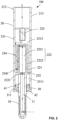
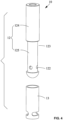
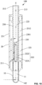
- the disclosure provides a smoke generation and filtration device 100.
- the smoke generation and filtration device comprises a heating component 10 and a smoke filtration component 20. Water is added to the smoke filtration component 20.
- the heating component 10 heats the tobacco material to generate smoke. The smoke is then passed through the smoke filtration component 20 , so that the toxins are filtered out from the smoke that passes through the water.
- the smoke filtration component 20 comprises a first end 211 and a second end 212 opposite to the first end.
- the heating component 10 is detachably connected to the first end 211 , and the second end 212 comprises a contact part 213 through which a user inhales the smoke.
- the heating component 10 and the contact part 213 are disposed at both ends of the smoke filtration component 20.
- the contact part 213 and the heating component 10 are respectively disposed at the upper and lower ends of the smoke filtration component 20 , enabling users to comfortably hold and smoke.
- the generated smoke flows through the lower end of the smoke filtration component 20 and encounters the water in the smoke filtration component 20 , allowing harmful substances to dissolve in the water. Therefore, the water effectively filters out the toxins from the smoke.
- the heating component 10 is detachably connected to the smoke filtration component 20 , enabling convenient and separate cleaning of each component after a period of use.
- the smoke filtration component 20 comprises a smoke filtration chamber 221 , a first smoke guide channel 222 , and a second smoke guide channel 223.
- One end of the first smoke guide channel 222 is connected to the heating component 10
- the other end of the first smoke guide channel 222 is connected to the smoke filtration chamber 221.
- one end of the second smoke guide channel 223 is connected to the smoke filtration chamber 221
- the other end of the second smoke guide channel 223 is connected to the contact part 213.
- the heating component 10 heats the tobacco material to generate smoke.
- the generated smoke flows out of the heating component 10 , passes through the first smoke guide channel 222 , and enters the smoke filtration chamber 221 for smoke filtration.
- the smoke enters the second smoke guide channel 223 and is finally released from the contact part 213 for user inhalation.
- the first smoke guide channel 222 comprises a first smoke inlet channel 2221 and a reflux channel 2222.
- the reflux channel 2222 is disposed between and connected to both the first smoke inlet channel 2221 and the smoke filtration chamber 221.
- the first smoke inlet channel 2221 is connected to the heating component 10.
- the first smoke inlet channel 2221 , the reflux channel 2222 , and the smoke filtration chamber 221 are sequentially disposed from inside to outside in the smoke filtration component, with the innermost layer being the first smoke inlet channel 2221.
- the generated smoke flows out of the heating component 10 , passes through the first smoke inlet channel 2221 and the reflux channel 2222 , sequentially, and enters the smoke filtration chamber 221 for smoke filtration.
- the smoke filtration component 20 comprises an outer tube 231 and an isolation plate 232.
- the isolation plate 232 comprises a first communication hole 2321.
- the isolation plate 232 is radially connected to the inner wall of the outer tube 231 , so as to separate the inner cavity of the outer tube 231 into a first cavity 2311 and a second cavity 2312.
- the heating component 10 is disposed inside the first cavity 2311 and extends out of the first cavity 2311.
- the smoke filtration chamber 221 , the first smoke guide channel 222 , and the second smoke guide channel 223 are disposed in the second cavity 2312.
- the heating component 10 is connected to the first smoke guide channel 222 via the first communication hole 2321.
- the first cavity 2311 is disposed at the lower end of the outer tube 231
- the second cavity 2312 is disposed at the upper end of the outer tube 231 , so that the heating component 10 is disposed inside the lower end of the outer tube 231.
- the second smoke guide channel 223 is disposed in the second cavity 2312 and is connected to the contact part 213 , so that the contact part 213 is disposed at the upper end of the outer tube 231.
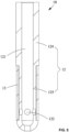
- the smoke filtration component 20 further comprises an inner tube 233 and a reflux tube 234.
- the reflux tube 234 is disposed around the inner tube 233. Both the inner tube 233 and the reflux tube 234 are disposed in the outer tube 231.
- the reflux tube 234 is disposed between the inner tube 233 and the outer tube 231.
- One end of the reflux tube 234 and one end of the inner tube 233 are both connected to the isolation plate 232.
- the other end of the reflux tube 234 is connected to a closure plate 235.
- a gap is formed between the other end of the reflux tube 234 and the other end of the inner tube 233.
- the inner cavity of the inner tube 233 functions as the first smoke inlet channel 2221 and communicates with the first communication hole 2321.
- the gap between the inner tube 233 and the reflux tube 234 functions as the reflux channel 2222.
- the one end of the reflux tube 234 is near the isolation plate 232 and comprises a through hole functioning as a first passage hole 2341.
- the reflux channel 2222 is connected to the smoke filtration chamber 221 via the first passage hole 2341.
- the smoke filtration component 20 further comprises a first smoke outlet tube 236 having a smaller diameter than the outer diameter of the outer tube 231.
- the first smoke outlet tube 236 is disposed in the second cavity 2312.
- One end of the first smoke outlet tube 236 is connected to the inner wall of the outer tube 231 , and the other end of the first smoke outlet tube 236 extends towards the first cavity 2311 and is spaced apart from the closure plate 235.
- the inner cavity of the first smoke outlet tube 236 functions as the second smoke guide channel 223.
- One end of the outer tube 231 is away from the heating component 10 and functions as the contact part 213.
- the smoke filtration component 20 comprises glass, allowing for observation of the water level in the smoke filtration chamber 221 ; as the generated smoke passes through the smoke filtration component 20 , no odors are produced, because glass is an environmentally friendly material and easy to clean.
- the smoke filtration component 20 comprises quartz or crystal.
- the heating component 10 comprises a second smoke inlet channel 11 connected to the smoke filtration component 20.
- the generated smoke flows through the second smoke inlet channel 11 and enters the smoke filtration component 20.
- the second smoke inlet channel 11 is connected to the first smoke inlet channel 2221 through the first communication hole 2321.
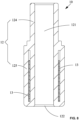
- the heating component 10 comprises a heating body 12 and a metal heating unit 13.
- the heating body 12 comprises a first smoke guiding chamber 121 and a second communication hole 122.
- the first smoke guiding chamber 121 is connected to the external environment via the second communication hole 122.
- the first smoke guiding chamber 121 communicates with the second smoke inlet channel 11.
- the metal heating unit 13 is disposed around the heating body 12.
- the heating component 10 is disposed in an induction coil, the induction coil is independent from the smoke generation and filtration device 100.
- the metal heating unit 13 heats up through the magnetic induction in the magnetic field generated by the induction coil.
- the metal heating unit 13 comprises stainless steel, which is easy to shape, cost-effective, and has excellent heating efficiency.
- the outer surface of the heating body 12 is concave, forming an installation groove 123.
- the metal heating unit 13 is disposed in the installation groove 123 , ensuring a smoother outer surface of the heating component 10.
- the heating body 12 comprises a connecting portion 124 and a heating portion 125 connected to the connecting portion 124.
- the connecting portion 124 is detachably connected to the first end 211 of the smoke filtration component 20.
- the heating portion 125 extends outward from the connecting portion 124 and is away from the second end 212 of the smoke filtration component 20.
- the heating portion 125 is disposed in the induction coil.
- the induction coil is independent from the smoke generation and filtration device 100. Both the metal heating unit 13 and the second communication hole 122 are disposed on the heating portion 125.
- the connecting portion 124 is disposed inside the first cavity 2311 and connected to the isolation plate 232 ; and the heating portion 125 extends outside the first cavity 2311, facilitating its placement within the induction coil.
- the heating component 10 is powered to produce heat and is inserted into the tobacco material.
- the tobacco material is then heated to generate smoke.
- the smoke passes through the second communication hole 122 , the second smoke inlet channel 11 , the first communication hole 2321, the first smoke inlet channel 2221, the reflux channel 2222 and the smoke filtration chamber 221 , sequentially, and then flows through the second smoke guide channel 223 , ultimately reaching the contact part 213 for the user to inhale.
- the heating body 12 comprises glass and thus is resistant to high temperatures. As the generated smoke passes through the heating body 12 , no odors are produced, because glass is an environmentally friendly material and easy to clean.
- the heating body 12 comprises quartz, agate, or crystal.
- the smoke generation and filtration device 100 further comprises a connecting member 30 disposed between the smoke filtration component 20 and the heating component 10.
- the smoke generation and filtration device 100 further comprises a first seal member 41 and a second seal member 42.
- the first seal member 41 is disposed between the outer tube 231 and the connecting member 30
- the second seal member 42 is disposed between the heating component 10 and the connecting member 30.
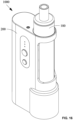
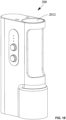
- the disclosure further provides a hookah 1000.
- the hookah comprises the smoke generation and filtration device 100 and a heater 200.
- the smoke generation and filtration device 100 is detachably disposed in the heater 200.
- the heater is used to heat the heating component 10.
- the smoke generation and filtration device 100 provides convenience for users to hold, smoke, clean, and effectively dissolve harmful substances in the water.
- the smoke generation and filtration device 100 is detachably disposed in the heater 200 , allowing for easy removal from the heater 200. While smoking, only the smoke generation and filtration device 100 is held for inhalation, resulting in a lightweight, easy to handle, and convenient portable experience. Furthermore, a malfunctioned smoke generation and filtration device 100 can be replaced without the need to replace the entire hookah 1000.
- the heater 200 comprises a housing 201 , a power supply 202 , and the induction coil 203.
- the housing 201 comprises a first chamber 2011 and a second chamber 2012.
- the power supply 202 is disposed in the first chamber 2011
- the induction coil 203 is electrically connected to the power supply 202 and disposed in the second chamber 2012.
- the smoke generation and filtration device 100 is disposed inside the second chamber 2012
- the induction coil 203 is disposed around the heating component 10.
- the power supply 202 supplies power to the induction coil 203.
- the heating component 10 heats up through the magnetic induction in the magnetic field generated by the induction coil 203.
- the smoke generation and filtration device 100 is removed from the second chamber 2012 and inserted into the tobacco material.
- the tobacco material is heated to produce smoke.
- the smoke passes through the second communication hole 122 , the second smoke inlet channel 11 , the first smoke inlet channel 2221 , the reflux channel 2222 and the smoke filtration chamber 221 , sequentially, and then flows through the second smoke guide channel 223 , ultimately reaching the contact part 213 for the user to inhale.
- the power supply 202 is detachably disposed in the first chamber 2011 , allowing for easy replacement when the battery is depleted.
- FIGS. 5 and 8 A second example of the smoke generation and filtration device is illustrated in FIGS. 5 and 8 . It is similar to Example 1 , except for the following specific differences: and in Example 1 , the metal heating unit 13 is disposed around the heating body 12 ; in this example, the heating body 12 further comprises a sidewall enclosing the first smoke guiding chamber 121 ; the metal heating unit 13 is embedded in the sidewall.
- the heating component 10 comprises the heating body 12 and the metal heating unit 13.
- the metal heating unit 13 is disposed in the cavity wall of the heating body 12 , forming the first smoke guiding chamber 121.
- the heating body 12 is a tubular structure comprising an upper through hole and a lower through hole.
- the first smoke guiding chamber 121 communicates with the first communication hole 2321 via the upper through hole, and the lower through hole functions as the second communication hole 122.
- the heating body 12 is a hollow cylindrical structure comprising a bottom wall.
- the second communication hole 122 is disposed on the bottom wall of the heating body 12.
- the contact part 213 in the example is different from Example 1.
- the smoke filtration component 20 further comprises a mouthpiece 237 disposed at one end of the outer tube 231 and away from the heating component 10.
- the mouthpiece 237 comprises a main body 2371 and a second smoke outlet tube 2372.
- the main body 2371 is connected to the wall of the outer tube 231.
- the second smoke outlet tube 2372 extends from the main body 2371 into the second cavity 2312 and is spaced apart from the closure plate 235.
- the inner cavity of the second smoke outlet tube 2372 functions as the second smoke guide channel 223.
- the main body 2371 functions as the contact part 213.
- the smoke generation and filtration device 100 , water pipe 1000, and their associated components provided in this embodiment can be optimized based on Embodiment 1.
- FIGS. 8 and 11 A third example of the smoke generation and filtration device is illustrated in FIGS. 8 and 11 . It is similar to Example 2 , except for the following specific differences: in Example 2 , the heating component 10 comprises a heating body 12 and a metal heating element 13 ; and in this example, the heating component 10 comprises a connecting pipe 14 and a metal container 15 for holding the tobacco material.
- the metal container 15 is detachably connected to the connecting pipe 14 and is disposed inside the induction coil 203.
- the inner cavity of the connecting pipe 14 communicates with the second smoke inlet channel 11.
- the metal container 15 comprises a third communication hole 151.
- the inner cavity of the connecting pipe 14 communicates with the external environment via the third communication hole 151.
- the power supply 202 provides power to the induction coil 203 , causing the metal container 15 to heat up through the magnetic induction in the magnetic field generated by the induction coil 203.
- the smoke generation and filtration device 100 is removed from the second chamber 2012, and the tobacco material is heated by the metal container 15 to generate smoke.
- the smoke passes through the third communication hole 151 , the second smoke inlet channel 11 , the first smoke inlet channel 2221 , the reflux channel 2222 and the smoke filtration chamber 221 , sequentially, and then flows through the second smoke guide channel 223 , ultimately reaching the contact part 213 for the user to inhale.
- the smoke generation and filtration device 100 the hookah 1000, and the components described herein can be further improved by referring to Examples 1 and 2.
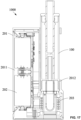
- a fourth example of the smoke generation and filtration device is illustrated and similar to Examples 1-3 , except for the following specific differences: in this example, the heating component 10 comprises a metal heating body 16.
- the metal heating body 16 comprises a second smoke guiding chamber 161 and a fourth communication hole 162.
- the second smoke guiding chamber 161 communicates with the external environment via the fourth communication hole 162.
- the second smoke guiding chamber 161 communicates with the second smoke inlet channel 11.
- One end of the metal heating body 16 is detachably connected to the first end 211 of the smoke filtration component 20 , and the other end of the metal heating body 16 is disposed in the induction coil 203.
- the induction coil 203 is independent from the smoke generation and filtration device.
- the fourth communication hole 162 is disposed at the other end of the metal heating body 16.
- the one end of the metal heating body 16 is closer to the smoke filtration component 20 and comprises a notch 163 for shielding electromagnetic interference.
- the heating component 10 further comprises a ceramic insulating member 17 with a hollow cavity.
- the ceramic insulating member 17 is disposed in the second smoke guiding chamber 161.
- the second smoke guiding chamber 161 comprises a chamber wall, and the ceramic insulating member 17 is attached to the chamber wall to prevent the smoke from escaping through the notch 163.
- the contact part 213 is different from that in Examples 1 to 3.
- the smoke filtration component 20 comprises a third smoke outlet tube 238 having a smaller diameter than the outer diameter of the outer tube 231.
- One end of the third smoke outlet tube 238 is connected to the closure plate 235 , and the other end of the third smoke outlet tube 238 extends outside the second cavity 2312.
- the one end of the third smoke outlet tube 238 is enclosed by a sidewall comprising a second passage hole 2381.
- the inner cavity of the third smoke outlet tube 238 functions as the second smoke guide channel 223.
- the smoke filtration chamber 221 communicates with the second smoke guide channel 223 via the second passage hole 2381.
- the third smoke outlet tube 238 comprises a section extending outside the second cavity 2312 , and the section functions as the contact part 213.
- the smoke generation and filtration device 100 is disposed in the second chamber 2012 and extends outside the second chamber 2012. In Example 1 , the smoke generation and filtration device 100 is completely disposed in the second chamber 2012.
- the smoke generation and filtration device 100 the hookah 1000 , and the components described herein can be further improved by referring to Examples 1-3.
Landscapes
- Cigarettes, Filters, And Manufacturing Of Filters (AREA)
- Electric Stoves And Ranges (AREA)
- Manufacturing Of Cigar And Cigarette Tobacco (AREA)
Applications Claiming Priority (5)
| Application Number | Priority Date | Filing Date | Title |
|---|---|---|---|
| CN202011471675.6A CN112493537A (zh) | 2020-12-15 | 2020-12-15 | 一种新型高频加热可分离式水烟 |
| CN202023007971.9U CN215603147U (zh) | 2020-12-15 | 2020-12-15 | 一种新型高频加热可分离式水烟 |
| CN202110143124.5A CN112790426A (zh) | 2021-02-02 | 2021-02-02 | 一种高频发热与加热可分离的水烟 |
| CN202120294195.0U CN217242660U (zh) | 2021-02-02 | 2021-02-02 | 一种高频发热与加热可分离的水烟 |
| PCT/CN2021/137898 WO2022127784A1 (fr) | 2020-12-15 | 2021-12-14 | Dispositif de génération et de filtration de fumée et e-narguilé |
Publications (2)
| Publication Number | Publication Date |
|---|---|
| EP4265131A1 true EP4265131A1 (fr) | 2023-10-25 |
| EP4265131A4 EP4265131A4 (fr) | 2024-07-17 |
Family
ID=82060045
Family Applications (1)
| Application Number | Title | Priority Date | Filing Date |
|---|---|---|---|
| EP21905713.0A Pending EP4265131A4 (fr) | 2020-12-15 | 2021-12-14 | Dispositif de génération et de filtration de fumée et e-narguilé |
Country Status (4)
| Country | Link |
|---|---|
| US (1) | US20230320413A1 (fr) |
| EP (1) | EP4265131A4 (fr) |
| CA (1) | CA3202463A1 (fr) |
| WO (1) | WO2022127784A1 (fr) |
Family Cites Families (12)
| Publication number | Priority date | Publication date | Assignee | Title |
|---|---|---|---|---|
| US20140048085A1 (en) * | 2012-03-28 | 2014-02-20 | Borealis Technical Limited | Cooling filter for cigarettes and smoking articles |
| US10004263B2 (en) * | 2014-03-07 | 2018-06-26 | Huizhou Kimree Technology Co., Ltd. Shenzhen Branch | Electronic cigarette provided with accumulated E-liquid removal function, and method therefor |
| CN204335820U (zh) * | 2014-04-24 | 2015-05-20 | 惠州市吉瑞科技有限公司 | 一种电子烟 |
| CN105559149B (zh) * | 2016-03-11 | 2018-06-19 | 深圳市赛尔美电子科技有限公司 | 一种烤烟器 |
| CN205682426U (zh) * | 2016-06-07 | 2016-11-16 | 深圳市和宏实业股份有限公司 | 一种电子烟 |
| CN108201170B (zh) * | 2016-12-16 | 2021-01-01 | 深圳市赛尔美电子科技有限公司 | 水烟烟具 |
| CN208318252U (zh) * | 2018-06-23 | 2019-01-04 | 深圳市富瑞灵珂实业有限公司 | 烟雾发生器 |
| CN208925256U (zh) * | 2018-09-30 | 2019-06-04 | 深圳市艾瑞斯电子有限公司 | 一种两用吸入型玻璃管水过滤点烟装置 |
| CN209573239U (zh) * | 2019-02-14 | 2019-11-05 | 深圳市英霏特科技有限公司 | 一种新型吸烟装置 |
| CN211510569U (zh) * | 2019-08-19 | 2020-09-18 | 深圳市你我网络科技有限公司 | 电子烟 |
| CN112493537A (zh) * | 2020-12-15 | 2021-03-16 | 深圳易佳特科技有限公司 | 一种新型高频加热可分离式水烟 |
| CN112790426A (zh) * | 2021-02-02 | 2021-05-14 | 深圳易佳特科技有限公司 | 一种高频发热与加热可分离的水烟 |
-
2021
- 2021-12-14 CA CA3202463A patent/CA3202463A1/fr active Pending
- 2021-12-14 EP EP21905713.0A patent/EP4265131A4/fr active Pending
- 2021-12-14 WO PCT/CN2021/137898 patent/WO2022127784A1/fr not_active Ceased
-
2023
- 2023-06-14 US US18/210,045 patent/US20230320413A1/en active Pending
Also Published As
| Publication number | Publication date |
|---|---|
| EP4265131A4 (fr) | 2024-07-17 |
| US20230320413A1 (en) | 2023-10-12 |
| WO2022127784A1 (fr) | 2022-06-23 |
| CA3202463A1 (fr) | 2022-06-23 |
Similar Documents
| Publication | Publication Date | Title |
|---|---|---|
| JP7543366B2 (ja) | 閉鎖底部気化器ポッドと気化器とを備えるシステム | |
| EP4096448B1 (fr) | Dispositif de génération d'aérosol doté d'une cartouche sensorielle | |
| JP7635315B2 (ja) | 蒸気供給システム用のヒータ | |
| JP2022524693A (ja) | ウィックを伴う電子タバコ | |
| JP7655483B2 (ja) | エアロゾル生成装置 | |
| JP7257424B2 (ja) | 非燃焼喫煙具 | |
| CA3132096C (fr) | Atomiseur pour systeme de fourniture de vapeur | |
| JP2018534908A (ja) | 電子たばこ | |
| JP7478244B2 (ja) | 漏れ防止を備えるエアロゾル発生システム | |
| CN114727669A (zh) | 吸烟替代组件 | |
| CN109171025A (zh) | 电子烟 | |
| CA3202463A1 (fr) | Dispositif de generation et de filtration de fumee et e-narguile | |
| CN112772991A (zh) | 一种雾化器、电子烟组件及电子烟 | |
| CN215958322U (zh) | 电源组件及气溶胶生成装置 | |
| CN208657984U (zh) | 电子烟 | |
| CN215013588U (zh) | 一种雾化器、电子烟组件及电子烟 | |
| CN209185753U (zh) | 电子烟的本体和电子烟 | |
| KR102729541B1 (ko) | 서셉터를 포함하는 액상 카트리지 및 이를 구비하는 에어로졸 발생 장치 | |
| EP4418906B1 (fr) | Cartouche pour dispositif de génération d'aérosols chauffés par induction | |
| CN109561737A (zh) | 一种加热模组及用于加热可抽吸材料的设备 | |
| CN209185763U (zh) | 电子烟 | |
| KR102754419B1 (ko) | 오염이 방지되는 액상 카트리지 및 이를 구비하는 에어로졸 발생 장치 | |
| RU2859000C2 (ru) | Картридж для индукционно нагреваемого устройства, генерирующего аэрозоль, и система для генерирования аэрозоля | |
| CN209314968U (zh) | 电子烟的本体组件和电子烟 | |
| CN209185749U (zh) | 电子烟 |
Legal Events
| Date | Code | Title | Description |
|---|---|---|---|
| STAA | Information on the status of an ep patent application or granted ep patent |
Free format text: STATUS: THE INTERNATIONAL PUBLICATION HAS BEEN MADE |
|
| PUAI | Public reference made under article 153(3) epc to a published international application that has entered the european phase |
Free format text: ORIGINAL CODE: 0009012 |
|
| STAA | Information on the status of an ep patent application or granted ep patent |
Free format text: STATUS: REQUEST FOR EXAMINATION WAS MADE |
|
| 17P | Request for examination filed |
Effective date: 20230630 |
|
| AK | Designated contracting states |
Kind code of ref document: A1 Designated state(s): AL AT BE BG CH CY CZ DE DK EE ES FI FR GB GR HR HU IE IS IT LI LT LU LV MC MK MT NL NO PL PT RO RS SE SI SK SM TR |
|
| DAV | Request for validation of the european patent (deleted) | ||
| DAX | Request for extension of the european patent (deleted) | ||
| STAA | Information on the status of an ep patent application or granted ep patent |
Free format text: STATUS: EXAMINATION IS IN PROGRESS |
|
| A4 | Supplementary search report drawn up and despatched |
Effective date: 20240618 |
|
| RIC1 | Information provided on ipc code assigned before grant |
Ipc: A24F 40/485 20200101ALN20240612BHEP Ipc: A24F 40/465 20200101ALN20240612BHEP Ipc: A24F 40/20 20200101ALN20240612BHEP Ipc: A24F 1/30 20060101AFI20240612BHEP |
|
| 17Q | First examination report despatched |
Effective date: 20240628 |