EP4265143A1 - Tige et chaussure la comprenant - Google Patents
Tige et chaussure la comprenant Download PDFInfo
- Publication number
- EP4265143A1 EP4265143A1 EP21920988.9A EP21920988A EP4265143A1 EP 4265143 A1 EP4265143 A1 EP 4265143A1 EP 21920988 A EP21920988 A EP 21920988A EP 4265143 A1 EP4265143 A1 EP 4265143A1
- Authority
- EP
- European Patent Office
- Prior art keywords
- layer
- disposed
- holes
- low stiffness
- foot
- Prior art date
- Legal status (The legal status is an assumption and is not a legal conclusion. Google has not performed a legal analysis and makes no representation as to the accuracy of the status listed.)
- Granted
Links
Images





Classifications
-
- A—HUMAN NECESSITIES
- A43—FOOTWEAR
- A43B—CHARACTERISTIC FEATURES OF FOOTWEAR; PARTS OF FOOTWEAR
- A43B23/00—Uppers; Boot legs; Stiffeners; Other single parts of footwear
- A43B23/02—Uppers; Boot legs
- A43B23/0245—Uppers; Boot legs characterised by the constructive form
-
- A—HUMAN NECESSITIES
- A43—FOOTWEAR
- A43B—CHARACTERISTIC FEATURES OF FOOTWEAR; PARTS OF FOOTWEAR
- A43B23/00—Uppers; Boot legs; Stiffeners; Other single parts of footwear
- A43B23/02—Uppers; Boot legs
- A43B23/0205—Uppers; Boot legs characterised by the material
- A43B23/0235—Different layers of different material
-
- A—HUMAN NECESSITIES
- A43—FOOTWEAR
- A43B—CHARACTERISTIC FEATURES OF FOOTWEAR; PARTS OF FOOTWEAR
- A43B1/00—Footwear characterised by the material
- A43B1/02—Footwear characterised by the material made of fibres or fabrics made therefrom
- A43B1/04—Footwear characterised by the material made of fibres or fabrics made therefrom braided, knotted, knitted or crocheted
-
- A—HUMAN NECESSITIES
- A43—FOOTWEAR
- A43B—CHARACTERISTIC FEATURES OF FOOTWEAR; PARTS OF FOOTWEAR
- A43B23/00—Uppers; Boot legs; Stiffeners; Other single parts of footwear
- A43B23/02—Uppers; Boot legs
- A43B23/0205—Uppers; Boot legs characterised by the material
- A43B23/024—Different layers of the same material
-
- A—HUMAN NECESSITIES
- A43—FOOTWEAR
- A43B—CHARACTERISTIC FEATURES OF FOOTWEAR; PARTS OF FOOTWEAR
- A43B23/00—Uppers; Boot legs; Stiffeners; Other single parts of footwear
- A43B23/02—Uppers; Boot legs
- A43B23/0245—Uppers; Boot legs characterised by the constructive form
- A43B23/0265—Uppers; Boot legs characterised by the constructive form having different properties in different directions
- A43B23/027—Uppers; Boot legs characterised by the constructive form having different properties in different directions with a part of the upper particularly flexible, e.g. permitting articulation or torsion
-
- A—HUMAN NECESSITIES
- A43—FOOTWEAR
- A43B—CHARACTERISTIC FEATURES OF FOOTWEAR; PARTS OF FOOTWEAR
- A43B7/00—Footwear with health or hygienic arrangements
- A43B7/06—Footwear with health or hygienic arrangements ventilated
- A43B7/08—Footwear with health or hygienic arrangements ventilated with air-holes, with or without closures
Definitions
- the present invention relates to an upper and a shoe including the same.
- Patent Literature 1 discloses an upper including a first layer, a second layer disposed with a space from the first layer, and a third layer disposed between the first layer and the second layer.
- the upper disclosed in Patent Literature 1 has a point in which the third layer is disposed and a point in which the third layer is not disposed.
- Patent Literature 1 JP 2017-537715 A
- the stiffness of the point in which the third layer is not disposed is lower than the stiffness of the point in which the third layer is disposed.
- the present invention has been made in view of the above, and a purpose of the present invention is to obtain an upper capable of locally reducing the stiffness of the upper as compared with a conventional upper.
- an upper includes an upper body covering the instep of a foot.
- An upper body includes a first layer, a second layer disposed with a gap from the first layer, and a third layer connecting the first layer and the second layer.
- a part of the upper body is disposed with a low stiffness region having lower stiffness than an adjacent region. At least a part of the low stiffness region has a point in which the third layer is not disposed.
- a plurality of holes is disposed in at least a part of a portion of the first layer and the second layer of the low stiffness region corresponding to the point in which the third layer is not disposed.
- An upper according to the present invention has an effect of locally reducing the stiffness of the upper as compared with a conventional upper.
- a direction in which a shoe center axis, which is a perpendicular line passing through a shoe center in a plan view of a shoe, extends is referred to as a front-rear direction
- a direction orthogonal to the front-rear direction in a plan view of the shoe is referred to as a foot width direction.
- a direction directed from the end on the side where a portion of an upper covering the rearfoot of a foot is positioned toward the end on the side where a portion covering the forefoot of the foot is positioned is referred to as a front side
- a direction directed from the end on the side where a portion of the upper covering the forefoot of the foot is positioned toward the end on the side where a portion of the upper covering the rearfoot of the foot is positioned is referred to as a rear side.
- a median side of a foot in the anatomical position is referred to as a medial foot side
- the side opposite to the median side of the foot in the anatomical position is referred to as a lateral foot side. That is, the side closer to the median line in the anatomical position is referred to as the medial foot side, and the side farther from the median line in the anatomical position is referred to as the lateral foot side.
- a line along the foot width direction passing through a position corresponding to 25% to 50% of the dimension in the front-rear direction of the upper from the front end of the upper is defined as a first boundary line
- a line along the foot width direction passing through a position corresponding to 55% to 80% of the dimension in the front-rear direction of the upper from the front end of the upper is defined as a second boundary line
- a portion positioned in front of the first boundary line is referred to as an upper forefoot portion
- a portion sandwiched between the first boundary line and the second boundary line is referred to as an upper midfoot portion
- a portion positioned behind the second boundary line is referred to as an upper rearfoot portion.
- the upper forefoot portion corresponds to a portion covering the forefoot of a foot of a wearer with a standard body shape
- the upper midfoot portion corresponds to a portion covering the midfoot of a foot of a wearer with a standard body shape
- the upper rearfoot portion corresponds to a portion covering the rearfoot of a foot of a wearer with a standard body shape.
- the first boundary line is a line roughly along the MP joint of a wearer with a standard body shape
- the second boundary line is a line roughly along the Chopart joint of a wearer with a standard body shape.
- a height direction means a direction orthogonal to both the front-rear direction and the foot width direction unless otherwise specified
- a thickness means a dimension in the height direction unless otherwise specified.
- FIG. 1 is a plan view of a shoe 1 according to a first embodiment of the present invention.
- FIG. 2 is a side view of the shoe 1 on a lateral foot side according to the first embodiment.
- FIGS. 1 and 2 only the shoe 1 for a left foot is illustrated. Since the shoe 1 has a right-left symmetrical structure for a left foot and a right foot, only the shoe 1 for a left foot is described in the present embodiment, and the description of the shoe 1 for a right foot is omitted.
- the shoe 1 is, for example, a shoe for running or walking, a shoe for climbing, or a shoe for sports such as tennis and basketball.
- the shoe 1 includes an upper 2 and a sole 3 positioned below the upper 2.
- the upper 2 includes an upper body 20, a shoe tongue 21, and a shoelace 22.
- the upper body 20 covers a part on the instep side of a foot.
- a foot insertion opening 20a for inserting a foot of a wearer and an opening 20b communicating with the foot insertion opening 20a and extending from the foot insertion opening 20a to the front side are disposed.
- a plurality of string passing portions 20c spaced apart from each other in the front-rear direction is disposed.
- the structure of the string passing portions 20c is not particularly limited as long as a shoelace 22 can be passed therethrough, but in the present embodiment, the string passing portions 20c are through holes that pass through the upper body 20 in the vertical direction.
- a part of the upper body 20 is disposed with a low stiffness region 4. Details of the low stiffness region 4 are described later.
- the shoe tongue 21 is a member for protecting the instep of a wearer.
- the shoe tongue 21 covers the opening 20b inside the upper body 20.
- the shoe tongue 21 is fixed to the upper body 20 by stitching, welding, bonding, or a combination thereof.
- woven fabric, knitted fabric, synthetic leather, or resin is used for example.
- a double raschel warp knitted fabric knitted with polyester yarn is preferably used as the material of the upper body 20 and the shoe tongue 21.
- the material of the upper body 20 and the shoe tongue 21 is not limited to those exemplified.
- the shoelace 22 is a string-like member that is alternately passed through the string passing portions 20c disposed at both side edges of the opening 20b in the foot width direction, and is detachably attached to the upper body 20.
- the sole 3 covers the sole of a foot.
- the sole 3 includes an outsole 30 and a midsole 31.
- the sole 3 is fixed to the upper body 20 by stitching, welding, bonding, or a combination thereof.
- the lower surface of the outsole 30 serves as a ground contact surface 30a to be contacted on the ground.
- the midsole 31 is positioned on the upper surface of the outsole 30 and has a cushioning property. Note that the outsole 30 may be integrated with the midsole 31.
- the midsole 31 integrated with the outsole 30 is also referred to as a "unisole".
- the sole 3 includes an inner sole (not illustrated) that covers the lower opening of the upper body 20.
- the inner sole is fixed to the upper surface of the midsole 31 by bonding or welding.
- the inner sole is fixed to the lower edge of the above upper body 20 by stitching.
- the sole 3 may have a structure in which the inner sole is omitted.
- the shoe 1 may include an insole. If the shoe 1 includes an insole, the insole is installed on the sole 3 inside the upper 2.
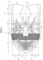
- FIG. 3 is a developed view of the upper 2 according to the first embodiment.
- FIG. 4 is a cross-sectional view taken along line IV-IV in FIG. 3 .
- FIG. 5 is a cross-sectional view taken along line V-V in FIG. 3 .
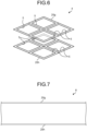
- FIG. 6 is a perspective view schematically illustrating a part of the low stiffness region 4.
- FIG. 7 is a cross-sectional view taken along line VII-VII in FIG. 3 .
- the upper body 20 includes an upper forefoot portion 23 which is a portion covering a forefoot of a foot of a wearer with a standard body shape, an upper midfoot portion 24 which is a portion covering a midfoot of a foot of a wearer with a standard body shape, and an upper rearfoot portion 25 which is a portion covering a rearfoot of a foot of a wearer with a standard body shape.
- the upper forefoot portion 23, the upper midfoot portion 24, and the upper rearfoot portion 25 are connected in this order in the front-rear direction from the front side of the upper body 20.
- the upper forefoot portion 23 is positioned in front of the first boundary line S1.
- the upper midfoot portion 24 is positioned between the first boundary line S1 and the second boundary line S2.
- the upper rearfoot portion 25 is positioned behind the second boundary line S2.
- a line along the front-rear direction passing through a position corresponding to 50% of the dimension in the foot width direction from a shoe center axis C to the edge on the lateral-most foot side is defined as a third boundary line S3, and a line along the front-rear direction passing through a position corresponding to 50% of the dimension in the foot width direction from the shoe center axis C to the edge on the medial-most foot side is defined as a fourth boundary line S4.
- a portion positioned on the lateral foot side from the third boundary line S3 is referred to as a lateral-foot-side side face portion 20d of the upper body 20
- a portion sandwiched between the third boundary line S3 and the fourth boundary line S4 is referred to as a center portion 20e of the upper body 20
- a portion positioned on the medial foot side from the fourth boundary line S4 is referred to as a medial-foot-side side face portion 20f of the upper body 20.
- the upper body 20 includes a first layer 20g, a second layer 20h disposed with a gap from the first layer 20g, and a third layer 20i connecting the first layer 20g and the second layer 20h.
- the first layer 20g, the second layer 20h, and the third layer 20i are integrally disposed of a single material.
- the first layer 20g is a layer facing the outside of the upper body 20.
- the second layer 20h is a layer facing the inside of the upper body 20.
- the third layer 20i includes a plurality of linear bodies 20j. Each linear body 20j is disposed to reciprocate a plurality of times between the first layer 20g and the second layer 20h.
- Each linear body 20j is, for example, a fiber, a thread obtained by bundling a plurality of fibers, or the like.
- a direction in which the first layer 20g, the second layer 20h, and the third layer 20i are stacked is referred to as a stacking direction.
- the upper body 20 is disposed with the low stiffness region 4, a plurality of first through holes 6, a plurality of second through holes 7, and a plurality of non-hole regions 8.
- the non-hole regions 8 are illustrated with dot hatching in order to clarify the ranges of the non-hole regions 8.
- the number of the first through holes 6 and the number of the second through holes 7 may be appropriately increased or decreased, and FIG. 3 illustrates a case in which the number of the first through holes 6 and the number of the second through holes 7 are different from those in FIGS. 1 and 2 .
- the low stiffness region 4 is disposed in the upper forefoot portion 23 and extends in the foot width direction.
- the low stiffness region 4 is disposed from the lateral-foot-side boundary of the upper body 20 with the sole 3 illustrated in FIG. 2 through the front of the opening 20b to the medial-foot-side boundary with the sole 3.
- the shape of the low stiffness region 4 in plan view is not particularly limited, but is substantially band-shaped in the present embodiment.
- the third layer 20i is not disposed in the low stiffness region 4. That is, in the present embodiment, the third layer 20i is not disposed over the entire low stiffness region 4.
- a plurality of holes 5 is disposed in a portion of the first layer 20g and the second layer 20h of the low stiffness region 4 corresponding to the point in which the third layer 20i is not disposed.
- the holes 5 have substantially the same shape in the first layer 20g and the second layer 20h at positions corresponding to each other in the stacking direction.
- the shape of the holes 5 in plan view is a rhombus in the present embodiment.
- substantially the same shape means a state in which the shape and the opening area of the holes 5 are completely the same between the first layer 20g and the second layer 20h, a state in which the shape and the opening area of the holes 5 are not strictly the same but slightly different between the first layer 20g and the second layer 20h due to a manufacturing error or the like, and a state in which the opening area of the holes 5 is originally intentionally made different between the first layer 20g and the second layer 20h.
- the first through holes 6 are disposed in the upper forefoot portion 23 in front of the low stiffness region 4.
- the first through holes 6 are disposed with a space from each other in the front-rear direction and the foot width direction.
- the shape of the first through holes 6 in plan view is not particularly limited, but is a circle or an ellipse in the present embodiment.
- the total opening area of the first through holes 6 positioned in the center portion 20e of the upper body 20 in the foot width direction is defined as a first total opening area
- the total opening area of the first through holes 6 positioned in the lateral-foot-side side face portion 20d and the medial-foot-side side face portion 20f of the upper body 20 in the foot width direction is defined as a second total opening area.
- the first total opening area is larger than the second total opening area.
- the first through holes 6 are disposed only in the first layer 20g.
- the third layer 20i is disposed at positions corresponding to the first through holes 6 in the stacking direction.
- the second through holes 7 are disposed in the upper midfoot portion 24 behind the low stiffness region 4.
- the second through holes 7 are disposed on both sides in the foot width direction across the opening 20b and the foot insertion opening 20a.
- the second through holes 7 are disposed from the vicinity of the rear end of the low stiffness region 4 over the rear side from the non-hole region 8 positioned rearmost.
- the second through holes 7 are not disposed in the portion with the non-hole regions 8.
- the second through holes 7 are disposed with a space from each other in the front-rear direction and the foot width direction.
- the shape of the second through holes 7 in plan view is not particularly limited, but is a circle or an ellipse in the present embodiment.
- the second through holes 7 are disposed only in the first layer 20g, and the third layer 20i is disposed at positions corresponding to the second through holes 7 in the stacking direction. Since, in the low stiffness region 4, the holes 5 are disposed in the first layer 20g and the second layer 20h, and the third layer 20i is not disposed at the positions corresponding to the holes 5 in the stacking direction, the stiffness of the low stiffness region 4 is lower than the stiffness of the region where the first through holes 6 and the second through holes 7 are disposed.
- the non-hole regions 8 are disposed in the upper midfoot portion 24 and extends in the foot width direction.
- the non-hole regions 8 are disposed on both sides in the foot width direction across the opening 20b.
- the non-hole regions 8 are disposed at right-left symmetrical positions across the opening 20b.
- the number of the non-hole regions 8 is not particularly limited, but there are four non-hole regions 8 in the present embodiment; two of them are disposed on the lateral foot side of the opening 20b, and the other two are disposed on the medial foot side.
- the two non-hole regions 8 positioned on the lateral foot side are disposed with a space from each other in the front-rear direction.
- the two non-hole regions 8 positioned on the medial foot side are disposed with a space from each other in the front-rear direction. As illustrated in FIG. 7 , in each non-hole region 8, there are no holes in the first layer 20g and the second layer 20h, and the third layer 20i is not disposed over the entire region. Since, in the low stiffness region 4, the holes 5 are disposed in the first layer 20g and the second layer 20h, and the third layer 20i is not disposed at positions corresponding to the holes 5 in the stacking direction, the stiffness of the low stiffness region 4 is lower than the stiffness of the non-hole regions 8.
- the first through holes 6, the second through holes 7, and the non-hole regions 8 illustrated in FIG. 3 there are no holes in the first layer 20g and the second layer 20h, and the third layer 20i is disposed.
- the low stiffness region 4 is adjacent to the standard region 9 in the present embodiment.
- the low stiffness region 4 has lower stiffness than the adjacent standard region 9.
- the upper 2 includes the upper body 20 that covers the instep of a foot as illustrated in FIG. 1
- the upper body 20 includes the first layer 20g, the second layer 20h disposed with a gap from the first layer 20g, and the third layer 20i connecting the first layer 20g and the second layer 20h as illustrated in FIG. 4 .
- a part of the upper body 20 is disposed with the low stiffness region 4 having lower stiffness than the adjacent region, and the third layer 20i is not disposed in the low stiffness region 4.
- a plurality of holes 5 is disposed in a portion of the first layer 20g and the second layer 20h of the low stiffness region 4 corresponding to the point in which the third layer 20i is not disposed.
- the stiffness of the low stiffness region 4 is lower than that with the conventional technique in which the holes 5 are not disposed in the first layer 20g and the second layer 20h, and it is possible to locally reduce the stiffness of the upper body 20 as compared with a conventional upper. Then, by disposing the low stiffness region 4 in a portion where bending or twisting of a foot occurs during movement, it is possible to enhance the followability of the upper body 20 with respect to bending or twisting of the foot of a wearer.
- the forefoot of a foot bends, which generates a bending point in the upper forefoot portion 23.
- the low stiffness region 4 is disposed in the upper forefoot portion 23 where the bending point is generated, it is possible to reduce the bending stiffness of the portion of the upper forefoot portion 23 where the bending point is generated. Accordingly, it is possible to reduce bending resistance of the upper body 20 during bending of a foot.
- the low stiffness region 4 is easily deformed following the bending of the foot, it is possible to ease the contact of the upper body 20 with the foot and reduce wrinkles generated in the upper body 20.
- the holes 5 have substantially the same shape in the first layer 20g and the second layer 20h at the positions corresponding to each other as illustrated in FIG. 6 , which makes it easier to deform the first layer 20g and the second layer 20h in the low stiffness region 4 in the same manner.
- the shape of the holes 5 in plan view is a rhombus as illustrated in FIG. 6
- the space between the opposite vertices of each hole 5 widens, which makes it easier for the first layer 20g and the second layer 20h to stretch, and the space between the opposite vertices of each hole 5 narrows, which makes it easier for the first layer 20g and the second layer 20h to shrink. Therefore, the first layer 20g and the second layer 20h in the low stiffness region 4 are easily deformed following stretching and shrinking of the skin of a foot during movement. Accordingly, it is possible to improve the fitting of the upper body 20 to the foot.
- the rhombic holes 5 have an advantage of having the largest mechanical deformation between the opposite vertices as compared with the 2n-polygonal holes 5 other than rhombic holes and of being most easily manufactured by a manufacturing machine that weaves the upper body 20.
- the upper body 20 illustrated in FIG. 4 is disposed of a single material, it is possible to easily manufacture the upper body 20 including the holes 5.
- FIG. 8 is a partially enlarged plan view of the low stiffness region 4 of the upper 2 according to a first modification of the first embodiment.
- the shape of the holes 5 in plan view may be, for example, a circle illustrated in FIG. 8 .
- all the holes 5 have the same size, but the sizes of some or all of the holes 5 may be different.
- FIG. 9 is a partially enlarged plan view of the low stiffness region 4 of the upper 2 according to a second modification of the first embodiment.
- the shape of the holes 5 in plan view may be, for example, an ellipse illustrated in FIG. 9 .
- the sizes of some of the holes 5 are different, but the sizes of all the holes 5 may be the same or different. Even if the shape of the holes 5 in plan view is a circle or an ellipse in this manner, it is possible to obtain an effect similar to that in the case in which the shape of the holes 5 in plan view is a 2n-polygon. Note that a mixture of two or more types of holes 5 of circular, elliptical, and 2n-polygonal shapes may be disposed in the low stiffness region 4.
- all the holes 5 have substantially the same shape in the first layer 20g and the second layer 20h at positions corresponding to each other in the stacking direction as illustrated in FIG. 6 , but at least one of the holes 5 is only required to have substantially the same shape in the first layer 20g and the second layer 20h at positions corresponding to each other in the stacking direction. Note that, as the number of the holes 5 having substantially the same shape in the first layer 20g and the second layer 20h at the positions corresponding to each other in the stacking direction are increased, the first layer 20g and the second layer 20h in the low stiffness region 4 are more easily deformed in the same manner.
- the third layer 20i is not disposed over the entire low stiffness region 4 as illustrated in FIG. 5 in the present embodiment, it is only required that at least a part of the low stiffness region 4 has a point in which the third layer 20i is not disposed.
- FIG. 10 is a plan view of a shoe 1A according to a second embodiment of the present invention.
- FIG. 11 is a side view of the shoe 1A on a lateral foot side according to the second embodiment.
- An upper 2A of the shoe 1A according to the second embodiment is different from the upper 2 according to the first embodiment in the structure of a low stiffness region 4A and in that the second through holes 7 and the non-hole regions 8 are omitted.
- portions that overlap with the first embodiment described above are denoted by the same reference signs, and the descriptions thereof are omitted.
- the low stiffness region 4A includes a first low stiffness region 40, a second low stiffness region 41, and a third low stiffness region 42.
- Holes 5 includes a plurality of first holes 50, a plurality of second holes 51, and a plurality of third holes 52.
- the first holes 50 are disposed side by side in the front-rear direction and the foot width direction in the first low stiffness region 40.
- the shape of first holes 50 in plan view is not particularly limited, but is a rhombus in the present embodiment.
- the second holes 51 are disposed side by side in the foot width direction in the second low stiffness region 41.
- the shape of second holes 51 in plan view is not particularly limited, but is a square or a rectangle in the present embodiment.
- the third holes 52 are disposed side by side in the front-rear direction and the foot width direction in the third low stiffness region 42.
- the shape of third holes 52 in plan view is not particularly limited, but is a rhombus in the present embodiment.
- FIG. 12 is a developed view of the upper 2A according to the second embodiment. Note that the number of first through holes 6 may be appropriately increased or decreased, and FIG. 12 illustrates a case in which the number of the first through holes 6 is different from that in FIGS. 10 and 11 .
- the first low stiffness region 40 is illustrated with dot hatching for convenience of description.
- the first low stiffness region 40 is disposed in an upper forefoot portion 23 and extends in the foot width direction.
- the first low stiffness region 40 is disposed from the lateral-foot-side boundary of the upper body 20A with a sole 3 illustrated in FIG. 11 through the front of an opening 20b to the medial-foot-side boundary with the sole 3.
- the shape of the first low stiffness region 40 in plan view is not particularly limited, but is substantially band-shaped in the present embodiment.
- FIG. 13 is a cross-sectional view taken along line XIII-XIII in FIG. 12 .
- the first low stiffness region 40 has a point in which a third layer 20i is disposed and a point in which the third layer 20i is not disposed.
- the first holes 50 are disposed in a portion of a first layer 20g and a second layer 20h of the first low stiffness region 40 corresponding to the point in which the third layer 20i is not disposed.
- the first holes 50 have substantially the same shape in the first layer 20g and the second layer 20h at positions corresponding to each other in the stacking direction.
- the shade of dot hatching illustrated in FIG. 12 represents a change in the density of linear bodies 20j illustrated in FIG. 13 in the first low stiffness region 40.
- the density of the linear bodies 20j increases from the front side toward the rear side.
- the density of the linear bodies 20j can increase from the front side toward the rear side.
- the stiffness of the first low stiffness region 40 increases from the front side toward the rear side.
- a region in which the first through holes 6 are disposed is adjacent to the front side of the first low stiffness region 40, and a standard region 9 is adjacent to the rear side of the first low stiffness region 40. Since the stiffness of the first low stiffness region 40 increases from the front side toward the rear side, it is possible to reduce the difference between the stiffness of the first low stiffness region 40 and the stiffness of the region in which the first through holes 6 are disposed and to reduce the difference between the stiffness of the first low stiffness region 40 and the stiffness of the standard region 9.
- the density of the linear bodies 20j may increase from the rear side toward the front side. That is, the density of the linear bodies 20j is only required to increase from one side to the other side in the front-rear direction. The density of the linear bodies 20j is only required to be appropriately adjusted to reduce the difference between the stiffness of the first low stiffness region 40 and the stiffness of the adjacent regions in front of and behind the first low stiffness region 40.
- the second low stiffness region 41 is disposed in an upper midfoot portion 24 and extends in the foot width direction.
- the second low stiffness region 41 is disposed on both sides in the foot width direction across the opening 20b and a foot insertion opening 20a.
- the shape of the second low stiffness region 41 in plan view is not particularly limited, but is substantially band-shaped in the present embodiment.
- the second low stiffness region 41 positioned on the lateral foot side of the opening 20b is disposed from the lateral-foot-side side edge of the opening 20b to the lateral-foot-side boundary of the upper body 20A with the sole 3.
- the number of second low stiffness regions 41 positioned on the lateral foot side of the opening 20b is not particularly limited, but is five in the present embodiment.
- the five second low stiffness regions 41 are disposed with a space from each other in the front-rear direction.
- the second low stiffness region 41 positioned on the medial foot side of the opening 20b is disposed from the medial-foot-side side edge of the opening 20b to the medial-foot-side boundary of the upper body 20A with the sole 3.
- the number of second low stiffness regions 41 positioned on the medial foot side of the opening 20b is not particularly limited, but is four in the present embodiment.
- the four second low stiffness regions 41 are disposed with a space from each other in the front-rear direction.
- FIG. 14 is a cross-sectional view taken along line XIV-XIV in FIG. 12 .
- the third layer 20i is not disposed in the second low stiffness region 41. That is, in the present embodiment, the third layer 20i is not disposed over the entire second low stiffness regions 41.
- the second holes 51 are disposed in a portion of the first layer 20g and the second layer 20h of the low stiffness region 4A corresponding to the point in which the third layer 20i is not disposed.
- the second holes 51 have substantially the same shape in the first layer 20g and the second layer 20h at positions corresponding to each other in the stacking direction.
- the third low stiffness region 42 is disposed in the upper midfoot portion 24 and extends in the foot width direction.
- the third low stiffness region 42 is disposed on the medial foot side of the opening 20b.
- the third low stiffness region 42 is disposed from the medial-foot-side side edge of the opening 20b to the medial-foot-side boundary of the upper body 20A with the sole 3.
- the shape of the third low stiffness region 42 in plan view is not particularly limited, but is a triangle in the present embodiment.
- the width along the front-rear direction of the third low stiffness region 42 is widened from the shoe center axis C side toward the medial foot side.
- the number of third low stiffness regions 42 is not particularly limited, but is one in the present embodiment.
- the third low stiffness region 42 is disposed between the second low stiffness region 41 positioned second from the front side and the second low stiffness region 41 positioned third from the front side. That is, two of the four second low stiffness regions 41 are disposed in front of the third low stiffness region 42, and the other two is disposed behind the third low stiffness region 42.
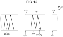
- FIG. 15 is a cross-sectional view taken along line XV-XV in FIG. 12 .
- the third low stiffness region 42 has a point in which the third layer 20i is disposed and a point in which the third layer 20i is not disposed.
- the point in which the third layer 20i is disposed and the point in which the third layer 20i is not disposed are alternately disposed along the foot width direction.
- the third holes 52 are disposed in a portion of the first layer 20g and the second layer 20h of the third low stiffness region 42 corresponding to the point in which the third layer 20i is not disposed.
- the third holes 52 have substantially the same shape in the first layer 20g and the second layer 20h at positions corresponding to each other in the stacking direction.
- the low stiffness region 4A includes the first low stiffness region 40 disposed in the upper forefoot portion 23 in which the bending point is generated as illustrated in FIG. 12 , it is possible to reduce the bending stiffness of the portion of the upper forefoot portion 23 where the bending point is generated. Accordingly, it is possible to reduce bending resistance of the upper body 20A during bending of a foot.
- the first low stiffness region 40 is easily deformed following the bending of the foot, it is possible to ease the contact of the upper body 20A with the foot and reduce wrinkles generated in the upper body 20A.
- the holes 5 includes the first holes 50 disposed side by side in the front-rear direction and the foot width direction in the first low stiffness region 40, and the shape of the first holes 50 is a rhombus. Accordingly, the space between the opposite vertices of each first hole 50 widens, which makes it easier for the first layer 20g and the second layer 20h to stretch as illustrated in FIG. 13 , and the space between the opposite vertices of each first hole 50 narrows, which makes it easier for the first layer 20g and the second layer 20h to shrink. Therefore, it is possible for the first layer 20g and the second layer 20h in the first low stiffness region 40 to be easily deformed following stretching and shrinking of the skin of a foot during movement. For this reason, it is possible to improve the fitting of the upper body 20A to the foot. A similar effect can be obtained also in the third low stiffness region 42 in which the rhombic third holes 52 illustrated in FIG. 12 are disposed.
- the third layer 20i includes the linear bodies 20j as illustrated in FIG. 13 , and the density of the linear bodies 20j in the first low stiffness region 40 increases from one side to the other side in the front-rear direction, it is possible to reduce the difference between the stiffness of the first low stiffness region 40 and the stiffness of the adjacent regions in front of and behind the first low stiffness region 40. Therefore, it is possible to control the change in the contact of the upper body 20A with a foot in the first low stiffness region 40 and the adjacent regions in front of and behind the first low stiffness region 40.
- the low stiffness region 4A includes the second low stiffness regions 41 and the third low stiffness region 42 disposed in the upper midfoot portion 24, it is possible to reduce the torsional stiffness of the upper midfoot portion 24. Accordingly, since the second low stiffness regions 41 and the third low stiffness region 42 are easily deformed following the distortion of the foot, it is possible to ease the contact of the upper body 20A with the foot and reduce wrinkles generated in the upper body 20A.
- the holes 5 include the second holes 51 disposed side by side in the front-rear direction and the foot width direction in the second low stiffness region 41, and the shape of the second holes 51 is a square or a rectangle. Accordingly, the first layer 20g and the second layer 20h in the second low stiffness region 41 illustrated in FIG. 14 are easily sheared and deformed. Therefore, it is possible for the first layer 20g and the second layer 20h in the second low stiffness region 41 to be easily deformed following distortion of the skin of a foot during movement. For this reason, it is possible to improve the fitting of the upper body 20A to the foot.
- first holes 50, the second holes 51, and the third holes 52 in plan view are not limited to the illustrated examples, and may be, for example, a circle, an ellipse, or a 2n-polygon other than a rhombus, a square, and a rectangle.
- At least one of the first holes 50 illustrated in FIG. 13 is only required to have substantially the same shape in the first layer 20g and the second layer 20h at positions corresponding to each other in the stacking direction. Note that, as the number of the first holes 50 having substantially the same shape in the first layer 20g and the second layer 20h at the positions corresponding to each other in the stacking direction are increased, the first layer 20g and the second layer 20h in the first low stiffness region 40 are more easily deformed in the same manner.
- At least one of the second holes 51 illustrated in FIG. 14 is only required to have substantially the same shape in the first layer 20g and the second layer 20h at positions corresponding to each other in the stacking direction. Note that, as the number of the second holes 51 having substantially the same shape in the first layer 20g and the second layer 20h at the positions corresponding to each other in the stacking direction are increased, the first layer 20g and the second layer 20h in the second low stiffness region 41 are more easily deformed in the same manner.
- At least one of the third holes 52 illustrated in FIG. 15 is only required to have substantially the same shape in the first layer 20g and the second layer 20h at positions corresponding to each other in the stacking direction. Note that, as the number of the third holes 52 having substantially the same shape in the first layer 20g and the second layer 20h at the positions corresponding to each other in the stacking direction are increased, the first layer 20g and the second layer 20h in the third low stiffness region 42 are more easily deformed in the same manner.
- the third layer 20i is not disposed over the entire second low stiffness region 41 as illustrated in FIG. 14 in the present embodiment, it is only required that at least a part of the second low stiffness region 41 has a point in which the third layer 20i is not disposed. In this case, it is preferable that, in the second low stiffness region 41, a point in which the third layer 20i is disposed and a point in which the third layer 20i is not disposed are alternately disposed along the foot width direction. Although there is a point in which the third layer 20i is not disposed in a part of each of the first low stiffness region 40 illustrated in FIG. 13 and the third low stiffness region 42 illustrated in FIG. 15 in the present embodiment, but the third layer 20i may not be disposed over the entire region of each of the first low stiffness region 40 and the third low stiffness region 42.
- the configurations described in the above embodiments merely show examples of the present invention and can be combined with another known technique, and a part of each configuration can be omitted or changed without departing from the gist of the present invention.
- the upper bodies 20 and 20A are disposed of a single material, but the upper bodies 20 and 20A may be disposed by combining a plurality of materials.
Landscapes
- Chemical & Material Sciences (AREA)
- Engineering & Computer Science (AREA)
- Materials Engineering (AREA)
- Health & Medical Sciences (AREA)
- Epidemiology (AREA)
- General Health & Medical Sciences (AREA)
- Public Health (AREA)
- Footwear And Its Accessory, Manufacturing Method And Apparatuses (AREA)
Applications Claiming Priority (1)
| Application Number | Priority Date | Filing Date | Title |
|---|---|---|---|
| PCT/JP2021/001978 WO2022157875A1 (fr) | 2021-01-21 | 2021-01-21 | Tige et chaussure la comprenant |
Publications (3)
| Publication Number | Publication Date |
|---|---|
| EP4265143A1 true EP4265143A1 (fr) | 2023-10-25 |
| EP4265143A4 EP4265143A4 (fr) | 2024-02-21 |
| EP4265143B1 EP4265143B1 (fr) | 2025-08-06 |
Family
ID=82548549
Family Applications (1)
| Application Number | Title | Priority Date | Filing Date |
|---|---|---|---|
| EP21920988.9A Active EP4265143B1 (fr) | 2021-01-21 | 2021-01-21 | Tige et chaussure la comprenant |
Country Status (5)
| Country | Link |
|---|---|
| US (1) | US12440000B2 (fr) |
| EP (1) | EP4265143B1 (fr) |
| JP (2) | JPWO2022157875A1 (fr) |
| CN (1) | CN116801761A (fr) |
| WO (1) | WO2022157875A1 (fr) |
Families Citing this family (4)
| Publication number | Priority date | Publication date | Assignee | Title |
|---|---|---|---|---|
| WO2023178085A1 (fr) | 2022-03-15 | 2023-09-21 | Nike Innovate C.V. | Article chaussant ayant une tige en couches |
| WO2024232983A1 (fr) * | 2023-05-07 | 2024-11-14 | Nike Innovate C.V. | Tige de chaussure ayant une structure tricotée unitaire et procédé de fabrication |
| US11896076B1 (en) | 2023-05-07 | 2024-02-13 | Nike, Inc. | Footwear upper having a unitary knit structure and method of manufacturing |
| DE102023209160A1 (de) * | 2023-09-20 | 2025-03-20 | Adidas Ag | Schuhoberteil für einen Schuh mit gestrickten Funktionselementen |
Family Cites Families (42)
| Publication number | Priority date | Publication date | Assignee | Title |
|---|---|---|---|---|
| US4133191A (en) * | 1976-04-09 | 1979-01-09 | Phillips Fibers Corporation | Knitted fabric having open areas |
| US4232458A (en) * | 1978-03-13 | 1980-11-11 | Wheelabrator Corp. Of Canada | Shoe |
| CA1247393A (fr) * | 1986-11-27 | 1988-12-28 | Andre Cournoyer | Tissu de tricot double avec des trous et des bandes de couleur |
| US5896758A (en) * | 1997-04-17 | 1999-04-27 | Malden Mills Industries, Inc. | Three-dimensional knit spacer fabric for footwear and backpacks |
| US6156406A (en) * | 1998-03-19 | 2000-12-05 | Malden Mills Industries, Inc. | Three-dimensional high-low bulk spacer fabric |
| US6401364B1 (en) * | 2000-06-15 | 2002-06-11 | Salomon S.A. | Ventilated shoe |
| US6482492B1 (en) * | 2001-05-25 | 2002-11-19 | Wen-Yau Hung | Spacermesh structure for shoemaking |
| US7047668B2 (en) * | 2003-07-24 | 2006-05-23 | Nike, Inc. | Article of footwear having an upper with a polymer layer |
| US6990755B2 (en) * | 2003-10-09 | 2006-01-31 | Nike, Inc. | Article of footwear with a stretchable upper and an articulated sole structure |
| US7347011B2 (en) * | 2004-03-03 | 2008-03-25 | Nike, Inc. | Article of footwear having a textile upper |
| US20070199210A1 (en) * | 2006-02-24 | 2007-08-30 | The Timberland Company | Compression molded footwear and methods of manufacture |
| US7574818B2 (en) | 2006-05-25 | 2009-08-18 | Nike, Inc. | Article of footwear having an upper with thread structural elements |
| US8544191B2 (en) * | 2007-04-10 | 2013-10-01 | Reebok International Limited | Smooth shoe uppers and methods for producing them |
| US8429835B2 (en) * | 2009-10-21 | 2013-04-30 | Nike, Inc. | Composite shoe upper and method of making same |
| FR2961068B1 (fr) * | 2010-06-11 | 2013-04-26 | Salomon Sas | Chaussure presentant un confort de marche ameliore |
| US9060570B2 (en) * | 2011-03-15 | 2015-06-23 | Nike, Inc. | Method of manufacturing a knitted component |
| US8800172B2 (en) | 2011-04-04 | 2014-08-12 | Nike, Inc. | Article of footwear having a knit upper with a polymer layer |
| US9150986B2 (en) * | 2011-05-04 | 2015-10-06 | Nike, Inc. | Knit component bonding |
| US20130312284A1 (en) * | 2011-05-27 | 2013-11-28 | Nike, Inc. | Article of Footwear Having Welded Upper |
| US20130303041A1 (en) * | 2012-03-14 | 2013-11-14 | Applied Ft Composite Solutions Inc. | Composite cushioning material with multiple strata |
| DE102012206062B4 (de) * | 2012-04-13 | 2019-09-12 | Adidas Ag | Schuhoberteil |
| US9635905B2 (en) * | 2012-12-10 | 2017-05-02 | Nike, Inc. | Upper having bonded differentially-oriented inner and outer reinforcing strips |
| US10863794B2 (en) * | 2013-06-25 | 2020-12-15 | Nike, Inc. | Article of footwear having multiple braided structures |
| JP6306590B2 (ja) * | 2013-08-07 | 2018-04-04 | 株式会社アシックス | シューズ |
| US8997529B1 (en) * | 2014-02-03 | 2015-04-07 | Nike, Inc. | Article of footwear including a monofilament knit element with peripheral knit portions |
| US10165830B2 (en) * | 2014-05-29 | 2019-01-01 | Asics Corporation | Shoe upper |
| TWM493278U (zh) * | 2014-10-21 | 2015-01-11 | Deertex Inc | 具有透氣耐磨梭織鞋面之鞋類組件 |
| MX2017007446A (es) | 2014-12-10 | 2017-10-20 | Nike Innovate Cv | Articulo de calzado con multiples estructuras trenzadas. |
| KR101557130B1 (ko) * | 2015-04-24 | 2015-10-02 | 송수복 | 이종 조직 직물 직조용 직기, 이를 이용하여 직조된 신발갑피 및 신발 |
| US20160345675A1 (en) * | 2015-05-26 | 2016-12-01 | Nike, Inc. | Hybrid Braided Article |
| EP3170419B1 (fr) | 2015-10-08 | 2019-05-15 | ASICS Corporation | Chaussure comportant une semelle et une tige |
| US10398190B2 (en) | 2016-02-23 | 2019-09-03 | Nike, Inc. | Article of footwear including portions configured for customization |
| US20170238658A1 (en) * | 2016-02-24 | 2017-08-24 | Under Armour, Inc. | Footwear Upper With Zonal Support Areas |
| WO2018009414A1 (fr) * | 2016-07-06 | 2018-01-11 | Nike Innovate C.V. | Article à couches multiples et procédé de fabrication |
| TWM539252U (zh) * | 2016-08-05 | 2017-04-11 | 巨大發展有限公司 | 熱塑性鞋面 |
| US10786035B2 (en) * | 2016-10-13 | 2020-09-29 | Under Armour, Inc. | Article of footwear with cooling features |
| EP3788194B1 (fr) * | 2018-04-30 | 2023-03-22 | Nike Innovate C.V. | Empeigne de chaussure pour un vêtement de pied ayant une structure de filet |
| DE102018212632B4 (de) * | 2018-07-27 | 2024-03-14 | Adidas Ag | Gestricktes oder gewirktes Oberteil für einen Schuh und Verfahren zu dessen Herstellung |
| JP7202870B2 (ja) * | 2018-12-13 | 2023-01-12 | 株式会社アシックス | 走行に適した靴 |
| CN113226104B (zh) * | 2018-12-19 | 2022-07-26 | 彪马欧洲股份公司 | 特别用于运动鞋的鞋帮 |
| DE102019208734B4 (de) * | 2019-06-14 | 2026-05-07 | Adidas Ag | Verfahren zum Herstellen eines abriebfesten Materials |
| CN112888337B (zh) * | 2019-09-30 | 2024-10-29 | 株式会社爱世克私 | 鞋以及鞋的制造方法 |
-
2021
- 2021-01-21 CN CN202180091173.7A patent/CN116801761A/zh active Pending
- 2021-01-21 WO PCT/JP2021/001978 patent/WO2022157875A1/fr not_active Ceased
- 2021-01-21 US US18/272,976 patent/US12440000B2/en active Active
- 2021-01-21 JP JP2022576288A patent/JPWO2022157875A1/ja active Pending
- 2021-01-21 EP EP21920988.9A patent/EP4265143B1/fr active Active
-
2025
- 2025-01-08 JP JP2025002696A patent/JP7799228B2/ja active Active
Also Published As
| Publication number | Publication date |
|---|---|
| EP4265143A4 (fr) | 2024-02-21 |
| US20240081481A1 (en) | 2024-03-14 |
| JP2025036756A (ja) | 2025-03-14 |
| JPWO2022157875A1 (fr) | 2022-07-28 |
| US12440000B2 (en) | 2025-10-14 |
| EP4265143B1 (fr) | 2025-08-06 |
| JP7799228B2 (ja) | 2026-01-15 |
| CN116801761A (zh) | 2023-09-22 |
| WO2022157875A1 (fr) | 2022-07-28 |
Similar Documents
| Publication | Publication Date | Title |
|---|---|---|
| US12440000B2 (en) | Upper and shoe including the same | |
| CN107205521B (zh) | 具有结合的抗拉线的编织鞋类鞋面 | |
| EP3432749B1 (fr) | Article chaussant | |
| WO2011004619A1 (fr) | Chaussure pourvue d'une structure de montage de lacet | |
| EP3616547A1 (fr) | Tige de chaussure | |
| US20250072562A1 (en) | Upper, shoe, and method for manufacturing upper | |
| JP2025131931A (ja) | アッパー及びこれを備えた靴 | |
| AU2019439573A1 (en) | Shoe | |
| CN115769931B (zh) | 鞋面以及鞋子 | |
| US20240335007A1 (en) | Shoe | |
| US20250107596A1 (en) | Upper, shoe, and method for manufacturing upper | |
| JP2020163174A (ja) | 靴 | |
| EP4088610A1 (fr) | Semelle et chaussure | |
| EP4520215A1 (fr) | Chaussure | |
| JP7656745B2 (ja) | シューズ | |
| EP4350059B1 (fr) | Tige pour une chaussure | |
| JP7618698B2 (ja) | アッパー及びこれを備えた靴 | |
| EP4573958A1 (fr) | Tige et chaussure | |
| JP7530996B2 (ja) | アッパー及びこれを備えた靴 | |
| CN119384233A (zh) | 鞋面及鞋 | |
| JP4957979B2 (ja) | 紐締めフィッティング構造を備えた靴 |
Legal Events
| Date | Code | Title | Description |
|---|---|---|---|
| STAA | Information on the status of an ep patent application or granted ep patent |
Free format text: STATUS: THE INTERNATIONAL PUBLICATION HAS BEEN MADE |
|
| PUAI | Public reference made under article 153(3) epc to a published international application that has entered the european phase |
Free format text: ORIGINAL CODE: 0009012 |
|
| STAA | Information on the status of an ep patent application or granted ep patent |
Free format text: STATUS: REQUEST FOR EXAMINATION WAS MADE |
|
| 17P | Request for examination filed |
Effective date: 20230720 |
|
| AK | Designated contracting states |
Kind code of ref document: A1 Designated state(s): AL AT BE BG CH CY CZ DE DK EE ES FI FR GB GR HR HU IE IS IT LI LT LU LV MC MK MT NL NO PL PT RO RS SE SI SK SM TR |
|
| A4 | Supplementary search report drawn up and despatched |
Effective date: 20240123 |
|
| RIC1 | Information provided on ipc code assigned before grant |
Ipc: A43B 7/08 20220101ALI20240117BHEP Ipc: A43B 1/04 20220101ALI20240117BHEP Ipc: A43B 23/02 20060101AFI20240117BHEP |
|
| DAV | Request for validation of the european patent (deleted) | ||
| DAX | Request for extension of the european patent (deleted) | ||
| STAA | Information on the status of an ep patent application or granted ep patent |
Free format text: STATUS: EXAMINATION IS IN PROGRESS |
|
| 17Q | First examination report despatched |
Effective date: 20241119 |
|
| GRAP | Despatch of communication of intention to grant a patent |
Free format text: ORIGINAL CODE: EPIDOSNIGR1 |
|
| STAA | Information on the status of an ep patent application or granted ep patent |
Free format text: STATUS: GRANT OF PATENT IS INTENDED |
|
| INTG | Intention to grant announced |
Effective date: 20250404 |
|
| GRAS | Grant fee paid |
Free format text: ORIGINAL CODE: EPIDOSNIGR3 |
|
| GRAA | (expected) grant |
Free format text: ORIGINAL CODE: 0009210 |
|
| STAA | Information on the status of an ep patent application or granted ep patent |
Free format text: STATUS: THE PATENT HAS BEEN GRANTED |
|
| AK | Designated contracting states |
Kind code of ref document: B1 Designated state(s): AL AT BE BG CH CY CZ DE DK EE ES FI FR GB GR HR HU IE IS IT LI LT LU LV MC MK MT NL NO PL PT RO RS SE SI SK SM TR |
|
| REG | Reference to a national code |
Ref country code: GB Ref legal event code: FG4D |
|
| REG | Reference to a national code |
Ref country code: CH Ref legal event code: EP |
|
| REG | Reference to a national code |
Ref country code: IE Ref legal event code: FG4D |
|
| REG | Reference to a national code |
Ref country code: DE Ref legal event code: R096 Ref document number: 602021035884 Country of ref document: DE |
|
| REG | Reference to a national code |
Ref country code: NL Ref legal event code: MP Effective date: 20250806 |
|
| PG25 | Lapsed in a contracting state [announced via postgrant information from national office to epo] |
Ref country code: IS Free format text: LAPSE BECAUSE OF FAILURE TO SUBMIT A TRANSLATION OF THE DESCRIPTION OR TO PAY THE FEE WITHIN THE PRESCRIBED TIME-LIMIT Effective date: 20251206 |
|
| PGFP | Annual fee paid to national office [announced via postgrant information from national office to epo] |
Ref country code: GB Payment date: 20251127 Year of fee payment: 6 |
|
| PG25 | Lapsed in a contracting state [announced via postgrant information from national office to epo] |
Ref country code: NO Free format text: LAPSE BECAUSE OF FAILURE TO SUBMIT A TRANSLATION OF THE DESCRIPTION OR TO PAY THE FEE WITHIN THE PRESCRIBED TIME-LIMIT Effective date: 20251106 |
|
| REG | Reference to a national code |
Ref country code: LT Ref legal event code: MG9D |
|
| PG25 | Lapsed in a contracting state [announced via postgrant information from national office to epo] |
Ref country code: PT Free format text: LAPSE BECAUSE OF FAILURE TO SUBMIT A TRANSLATION OF THE DESCRIPTION OR TO PAY THE FEE WITHIN THE PRESCRIBED TIME-LIMIT Effective date: 20251209 |
|
| PG25 | Lapsed in a contracting state [announced via postgrant information from national office to epo] |
Ref country code: FI Free format text: LAPSE BECAUSE OF FAILURE TO SUBMIT A TRANSLATION OF THE DESCRIPTION OR TO PAY THE FEE WITHIN THE PRESCRIBED TIME-LIMIT Effective date: 20250806 |
|
| PG25 | Lapsed in a contracting state [announced via postgrant information from national office to epo] |
Ref country code: HR Free format text: LAPSE BECAUSE OF FAILURE TO SUBMIT A TRANSLATION OF THE DESCRIPTION OR TO PAY THE FEE WITHIN THE PRESCRIBED TIME-LIMIT Effective date: 20250806 Ref country code: NL Free format text: LAPSE BECAUSE OF FAILURE TO SUBMIT A TRANSLATION OF THE DESCRIPTION OR TO PAY THE FEE WITHIN THE PRESCRIBED TIME-LIMIT Effective date: 20250806 |
|
| PGFP | Annual fee paid to national office [announced via postgrant information from national office to epo] |
Ref country code: FR Payment date: 20251128 Year of fee payment: 6 |
|
| PG25 | Lapsed in a contracting state [announced via postgrant information from national office to epo] |
Ref country code: GR Free format text: LAPSE BECAUSE OF FAILURE TO SUBMIT A TRANSLATION OF THE DESCRIPTION OR TO PAY THE FEE WITHIN THE PRESCRIBED TIME-LIMIT Effective date: 20251107 |
|
| PG25 | Lapsed in a contracting state [announced via postgrant information from national office to epo] |
Ref country code: SE Free format text: LAPSE BECAUSE OF FAILURE TO SUBMIT A TRANSLATION OF THE DESCRIPTION OR TO PAY THE FEE WITHIN THE PRESCRIBED TIME-LIMIT Effective date: 20250806 |
|
| PG25 | Lapsed in a contracting state [announced via postgrant information from national office to epo] |
Ref country code: LV Free format text: LAPSE BECAUSE OF FAILURE TO SUBMIT A TRANSLATION OF THE DESCRIPTION OR TO PAY THE FEE WITHIN THE PRESCRIBED TIME-LIMIT Effective date: 20250806 |
|
| PG25 | Lapsed in a contracting state [announced via postgrant information from national office to epo] |
Ref country code: PL Free format text: LAPSE BECAUSE OF FAILURE TO SUBMIT A TRANSLATION OF THE DESCRIPTION OR TO PAY THE FEE WITHIN THE PRESCRIBED TIME-LIMIT Effective date: 20250806 Ref country code: BG Free format text: LAPSE BECAUSE OF FAILURE TO SUBMIT A TRANSLATION OF THE DESCRIPTION OR TO PAY THE FEE WITHIN THE PRESCRIBED TIME-LIMIT Effective date: 20250806 |
|
| PG25 | Lapsed in a contracting state [announced via postgrant information from national office to epo] |
Ref country code: RS Free format text: LAPSE BECAUSE OF FAILURE TO SUBMIT A TRANSLATION OF THE DESCRIPTION OR TO PAY THE FEE WITHIN THE PRESCRIBED TIME-LIMIT Effective date: 20251106 |
|
| PG25 | Lapsed in a contracting state [announced via postgrant information from national office to epo] |
Ref country code: ES Free format text: LAPSE BECAUSE OF FAILURE TO SUBMIT A TRANSLATION OF THE DESCRIPTION OR TO PAY THE FEE WITHIN THE PRESCRIBED TIME-LIMIT Effective date: 20250806 |
|
| REG | Reference to a national code |
Ref country code: AT Ref legal event code: MK05 Ref document number: 1820722 Country of ref document: AT Kind code of ref document: T Effective date: 20250806 |
|
| PG25 | Lapsed in a contracting state [announced via postgrant information from national office to epo] |
Ref country code: SM Free format text: LAPSE BECAUSE OF FAILURE TO SUBMIT A TRANSLATION OF THE DESCRIPTION OR TO PAY THE FEE WITHIN THE PRESCRIBED TIME-LIMIT Effective date: 20250806 |
|
| PG25 | Lapsed in a contracting state [announced via postgrant information from national office to epo] |
Ref country code: DK Free format text: LAPSE BECAUSE OF FAILURE TO SUBMIT A TRANSLATION OF THE DESCRIPTION OR TO PAY THE FEE WITHIN THE PRESCRIBED TIME-LIMIT Effective date: 20250806 |
|
| PGFP | Annual fee paid to national office [announced via postgrant information from national office to epo] |
Ref country code: DE Payment date: 20251203 Year of fee payment: 6 |
|
| PG25 | Lapsed in a contracting state [announced via postgrant information from national office to epo] |
Ref country code: AT Free format text: LAPSE BECAUSE OF FAILURE TO SUBMIT A TRANSLATION OF THE DESCRIPTION OR TO PAY THE FEE WITHIN THE PRESCRIBED TIME-LIMIT Effective date: 20250806 |
|
| PG25 | Lapsed in a contracting state [announced via postgrant information from national office to epo] |
Ref country code: IT Free format text: LAPSE BECAUSE OF FAILURE TO SUBMIT A TRANSLATION OF THE DESCRIPTION OR TO PAY THE FEE WITHIN THE PRESCRIBED TIME-LIMIT Effective date: 20250806 |
|
| PG25 | Lapsed in a contracting state [announced via postgrant information from national office to epo] |
Ref country code: CZ Free format text: LAPSE BECAUSE OF FAILURE TO SUBMIT A TRANSLATION OF THE DESCRIPTION OR TO PAY THE FEE WITHIN THE PRESCRIBED TIME-LIMIT Effective date: 20250806 |
|
| PG25 | Lapsed in a contracting state [announced via postgrant information from national office to epo] |
Ref country code: EE Free format text: LAPSE BECAUSE OF FAILURE TO SUBMIT A TRANSLATION OF THE DESCRIPTION OR TO PAY THE FEE WITHIN THE PRESCRIBED TIME-LIMIT Effective date: 20250806 Ref country code: SK Free format text: LAPSE BECAUSE OF FAILURE TO SUBMIT A TRANSLATION OF THE DESCRIPTION OR TO PAY THE FEE WITHIN THE PRESCRIBED TIME-LIMIT Effective date: 20250806 |