EP4265192A1 - Gesundheitsüberwachungssystem für wassergeburten - Google Patents
Gesundheitsüberwachungssystem für wassergeburten Download PDFInfo
- Publication number
- EP4265192A1 EP4265192A1 EP23167482.1A EP23167482A EP4265192A1 EP 4265192 A1 EP4265192 A1 EP 4265192A1 EP 23167482 A EP23167482 A EP 23167482A EP 4265192 A1 EP4265192 A1 EP 4265192A1
- Authority
- EP
- European Patent Office
- Prior art keywords
- health
- sensor
- water
- signal
- mother
- Prior art date
- Legal status (The legal status is an assumption and is not a legal conclusion. Google has not performed a legal analysis and makes no representation as to the accuracy of the status listed.)
- Granted
Links
Images


Classifications
-
- A—HUMAN NECESSITIES
- A61—MEDICAL OR VETERINARY SCIENCE; HYGIENE
- A61B—DIAGNOSIS; SURGERY; IDENTIFICATION
- A61B8/00—Diagnosis using ultrasonic, sonic or infrasonic waves
- A61B8/02—Measuring pulse or heart rate
-
- A—HUMAN NECESSITIES
- A61—MEDICAL OR VETERINARY SCIENCE; HYGIENE
- A61B—DIAGNOSIS; SURGERY; IDENTIFICATION
- A61B8/00—Diagnosis using ultrasonic, sonic or infrasonic waves
- A61B8/08—Clinical applications
- A61B8/0866—Clinical applications involving foetal diagnosis; pre-natal or peri-natal diagnosis of the baby
-
- A—HUMAN NECESSITIES
- A61—MEDICAL OR VETERINARY SCIENCE; HYGIENE
- A61B—DIAGNOSIS; SURGERY; IDENTIFICATION
- A61B5/00—Measuring for diagnostic purposes; Identification of persons
- A61B5/0002—Remote monitoring of patients using telemetry, e.g. transmission of vital signals via a communication network
- A61B5/0004—Remote monitoring of patients using telemetry, e.g. transmission of vital signals via a communication network characterised by the type of physiological signal transmitted
- A61B5/0011—Foetal or obstetric data
-
- A—HUMAN NECESSITIES
- A61—MEDICAL OR VETERINARY SCIENCE; HYGIENE
- A61B—DIAGNOSIS; SURGERY; IDENTIFICATION
- A61B5/00—Measuring for diagnostic purposes; Identification of persons
- A61B5/02—Detecting, measuring or recording for evaluating the cardiovascular system, e.g. pulse, heart rate, blood pressure or blood flow
- A61B5/024—Measuring pulse rate or heart rate
- A61B5/02411—Measuring pulse rate or heart rate of foetuses
-
- A—HUMAN NECESSITIES
- A61—MEDICAL OR VETERINARY SCIENCE; HYGIENE
- A61B—DIAGNOSIS; SURGERY; IDENTIFICATION
- A61B5/00—Measuring for diagnostic purposes; Identification of persons
- A61B5/43—Detecting, measuring or recording for evaluating the reproductive systems
- A61B5/4306—Detecting, measuring or recording for evaluating the reproductive systems for evaluating the female reproductive systems, e.g. gynaecological evaluations
- A61B5/4343—Pregnancy and labour monitoring, e.g. for labour onset detection
- A61B5/4362—Assessing foetal parameters
-
- A—HUMAN NECESSITIES
- A61—MEDICAL OR VETERINARY SCIENCE; HYGIENE
- A61B—DIAGNOSIS; SURGERY; IDENTIFICATION
- A61B8/00—Diagnosis using ultrasonic, sonic or infrasonic waves
- A61B8/40—Positioning of patients, e.g. means for holding or immobilising parts of the patient's body
-
- A—HUMAN NECESSITIES
- A61—MEDICAL OR VETERINARY SCIENCE; HYGIENE
- A61B—DIAGNOSIS; SURGERY; IDENTIFICATION
- A61B8/00—Diagnosis using ultrasonic, sonic or infrasonic waves
- A61B8/42—Details of probe positioning or probe attachment to the patient
-
- A—HUMAN NECESSITIES
- A61—MEDICAL OR VETERINARY SCIENCE; HYGIENE
- A61B—DIAGNOSIS; SURGERY; IDENTIFICATION
- A61B8/00—Diagnosis using ultrasonic, sonic or infrasonic waves
- A61B8/42—Details of probe positioning or probe attachment to the patient
- A61B8/4245—Details of probe positioning or probe attachment to the patient involving determining the position of the probe, e.g. with respect to an external reference frame or to the patient
- A61B8/4254—Details of probe positioning or probe attachment to the patient involving determining the position of the probe, e.g. with respect to an external reference frame or to the patient using sensors mounted on the probe
-
- A—HUMAN NECESSITIES
- A61—MEDICAL OR VETERINARY SCIENCE; HYGIENE
- A61B—DIAGNOSIS; SURGERY; IDENTIFICATION
- A61B8/00—Diagnosis using ultrasonic, sonic or infrasonic waves
- A61B8/42—Details of probe positioning or probe attachment to the patient
- A61B8/4272—Details of probe positioning or probe attachment to the patient involving the acoustic interface between the transducer and the tissue
- A61B8/429—Details of probe positioning or probe attachment to the patient involving the acoustic interface between the transducer and the tissue characterised by determining or monitoring the contact between the transducer and the tissue
-
- A—HUMAN NECESSITIES
- A61—MEDICAL OR VETERINARY SCIENCE; HYGIENE
- A61B—DIAGNOSIS; SURGERY; IDENTIFICATION
- A61B8/00—Diagnosis using ultrasonic, sonic or infrasonic waves
- A61B8/44—Constructional features of the ultrasonic, sonic or infrasonic diagnostic device
- A61B8/4444—Constructional features of the ultrasonic, sonic or infrasonic diagnostic device related to the probe
-
- A—HUMAN NECESSITIES
- A61—MEDICAL OR VETERINARY SCIENCE; HYGIENE
- A61B—DIAGNOSIS; SURGERY; IDENTIFICATION
- A61B8/00—Diagnosis using ultrasonic, sonic or infrasonic waves
- A61B8/44—Constructional features of the ultrasonic, sonic or infrasonic diagnostic device
- A61B8/4477—Constructional features of the ultrasonic, sonic or infrasonic diagnostic device using several separate ultrasound transducers or probes
-
- A—HUMAN NECESSITIES
- A61—MEDICAL OR VETERINARY SCIENCE; HYGIENE
- A61B—DIAGNOSIS; SURGERY; IDENTIFICATION
- A61B8/00—Diagnosis using ultrasonic, sonic or infrasonic waves
- A61B8/44—Constructional features of the ultrasonic, sonic or infrasonic diagnostic device
- A61B8/4483—Constructional features of the ultrasonic, sonic or infrasonic diagnostic device characterised by features of the ultrasound transducer
- A61B8/4494—Constructional features of the ultrasonic, sonic or infrasonic diagnostic device characterised by features of the ultrasound transducer characterised by the arrangement of the transducer elements
-
- A—HUMAN NECESSITIES
- A61—MEDICAL OR VETERINARY SCIENCE; HYGIENE
- A61B—DIAGNOSIS; SURGERY; IDENTIFICATION
- A61B8/00—Diagnosis using ultrasonic, sonic or infrasonic waves
- A61B8/48—Diagnostic techniques
- A61B8/488—Diagnostic techniques involving Doppler signals
-
- A—HUMAN NECESSITIES
- A61—MEDICAL OR VETERINARY SCIENCE; HYGIENE
- A61B—DIAGNOSIS; SURGERY; IDENTIFICATION
- A61B2560/00—Constructional details of operational features of apparatus; Accessories for medical measuring apparatus
- A61B2560/02—Operational features
- A61B2560/0204—Operational features of power management
- A61B2560/0209—Operational features of power management adapted for power saving
Definitions
- Water births generally involve a mother undertaking at least a portion of the labor and delivery process while partially submerged in a pool of warm water.
- the pool may be provided by a tub or tank, which may be general purpose or made specifically for water births. Water birthing is becoming increasingly prevalent, because it may reduce the stress on and discomfort of the mother and the baby.
- the health of the mother and fetus are typically monitored during birthing processes, e.g., fetal heartrate, maternal heartrate, and/or uterine activity may be monitored.
- Electronic monitoring devices typically used to monitor the mother's and/or fetus's vitals are designed to be attached directly to the mother, and to communicate with external equipment. This is well-suited for traditional birthing, because the mother is typically in a bed for at least part of the process, permitting the monitoring devices to communicate with the external equipment wirelessly, through the air, or via cables extending from the monitoring devices coupled to the mother while she is in the bed.
- the monitoring devices secured directly to the mother are frequently underwater. As such, wireless communication between the monitoring devices and the external equipment is unreliable and/or unavailable. Accordingly, in water births, the monitoring devices attached to the mother communicate with external monitoring devices via cables. However, these devices, secured to the mother and tethered by wires to outside devices, tend to constrain the mother's movements. This can reduce the comfort and mitigate the stress-reduction benefits for the mother during the labor and delivery process.
- the system includes a health sensor configured to be coupled to a mother.
- the health sensor includes a first sensor configured to measure one or more health parameters of a mother, a fetus within the mother or both, a second sensor configured to generate a submerged signal representing whether the health sensor is at least partially submerged in water, and a transmitter configured to transmit communication signals representing data collected by the first sensor.
- One or more parameters of the communication signals change depending on whether the submerged signal represents that the health sensor is at least partially submerged.
- the communication signals include a first signal having a first frequency and a second signal having a second frequency, the first frequency being higher than the second frequency, wherein the transmitter transmits the first signal when the submerged signal represents that the health sensor is not submerged, and wherein the transmitter transmits the second signal when the submerged signal represents that the health sensor is at least partially submerged.
- the first signal has a higher power than the second signal.
- the health sensor includes a first antenna configured to emit the first signal and a second antenna configured to emit the second signal.
- the health sensor is configured to adapt the one or more parameters of the communication signals based on Effective Isotropic Radiated Power.
- the system also includes a converter having a first receiver configured to receive signals from the health sensor that do not travel through water, and a second receiver configured to receive signals from the health sensor that travel through the water.
- the system also includes a monitor in communication with the converter via a wireless or wired connection.
- the first receiver of the converter includes an antenna that extends above a surface of the water
- the second receiver of the converter includes an antenna that extends below the surface of the water
- the first sensor includes an ultrasonic transducer configured to measure maternal heartrate, fetal heartrate, uterine activity, fetal movement, or a combination thereof.
- the health sensor includes a power management module configured to adjust one or more parameters of the ultrasonic transducer based at least in part on a location of a detected fetal heartrate, so as to preserve battery life of the health sensor.
- the second sensor is configured to measure an impedance of an antenna of the transmitter, or the second sensor is configured to measure a resistivity of an environment in which the health sensor is positioned, or both.
- aspects of the present disclosure also include a method for monitoring health during a water birth.
- the method includes connecting a health sensor to a mother, measuring one or more health metrics of the mother, a fetus within the mother, or both while the mother is positioned in a tank having water therein, using the health sensor, and transmitting a first signal from the health sensor to a health monitoring device when the health sensor is not submerged in the water. The first signal does not travel through the water.
- the method also includes transmitting a second signal from the health sensor to the health monitoring device when the health sensor is at least partially submerged in the water. The second signal travels at least partially through the water to the health monitoring device.
- the method also includes determining that the health sensor is at least partially submerged in the water using a first sensor of the health sensor, and selecting to transmit the second signal and not to transmit the first signal in response to determining that the health sensor is at least partially submerged.
- the second signal travels at least partially through the water and at least partially through air to the health monitoring device.
- the first signal has a higher frequency than the second signal.
- the method further includes receiving the first and second signals using a converter connected to the tank, and transmitting a communication signal representing data received in the first signal, the second signal, or both from the converter to the health monitoring device.
- receiving the first and second signals using the converter includes receiving the first signal using a first antenna that extends above a surface of the water, and receiving the second signal using a second antenna that extends below the surface of the water.
- the method also includes adjusting a monitoring signal transmission parameter of the health sensor based on one or more measurements related to fetal heartrate taken by the health sensor.
- aspects of the present disclosure also include a system for monitoring health during a water birth.
- the system includes a health sensor configured to be coupled to a mother, the health sensor including a first antenna for transmitting first signals through air and not through water, and a second antenna for transmitting second signals at least partially through water. The first signals have a higher frequency than the second signals.
- the health sensor also includes an ultrasonic transducer configured to measure one or more health parameters of the mother, a fetus within the mother, or both, and a water sensor configured to detect when the health sensor is at least partially submerged in the water.
- the health sensor further includes a switch module connected to the first and second antenna.
- the switch module is configured to active the first antenna in response to the sensor detecting that the health sensor is not submerged, and the switch module is configured to activate the second antenna in response to the sensor detecting that the health sensor is submerged in the water.
- the system also includes a converter, hub, or both configured to receive the first and second signals. The first signals travel through the air to the converter, hub, or both, and the second signals travel at least partially through the water to the converter, hub, or both.
- he converter, hub, or both include a first antenna that extends out of the water and a second antenna that extends in the water.
- first and second features are formed in direct contact
- additional features may be formed interposing the first and second features, such that the first and second features may not be in direct contact.
- examples presented below may be combined in any combination of ways, e.g., any element from one exemplary example may be used in any other exemplary example, without departing from the scope of the disclosure.
- the invention may permit monitoring of a mother and/or fetus during water birthing without tethering the mother to communication cables.
- the invention may also permit free movement of the mother in the birthing tank by steering signals withing the water over a range of directions.
- the invention may be configured to preserve and extend battery life in the devices employed by dynamically controlling signal types and/or strength of the various monitoring and communication devices.
- the invention may provide low-loss signals in the context of communication of signals through different media (e.g., water and air).
- FIG. 1 illustrates a side, schematic view of a health monitoring system 100, according to an example.
- the health monitoring system 100 may include or be employed in conjunction with a birthing tank or tub 102.
- the tank 102 may be a general-purpose bathing tub, or may be constructed specifically for water births.
- the tank 102 may be an open-air tank, permitting a user (e.g., a mother) 104 to enter and exit the tank 102 by stepping over the side.
- a pool of water 106 may be held in the tank 102.
- the system 100 may also include one or more health sensors (two are shown: 110, 112). It will be appreciated that any number of health sensors may be employed, with the depiction of two in the illustration being merely an example.
- the system 100 may further include a monitoring device 114, which may be configured for communication with at least one of the health sensors 110, 112. The monitoring device 114 may be configured to interpret the signal received from the health sensors 110, 112 and, e.g., determine health measurements such as heartrate.
- At least one of the health sensors 112 may communicate with the monitoring device 114 via the other health sensor 110, while still being considered to be "in communication with" the monitoring device 114.
- the sensors 110, 112 may be connected together by a cable or in wireless communication with one another.
- the health sensors 110, 112 may not communicate directly with one another, but may individually communicate directly with the monitoring device 114.
- the health sensors 110, 112 may each include one or more transducers, which may be configured to convert electrical power to ultrasonic Doppler signals, or any other suitable signal type.
- the transducers may also be configured to convert received ultrasonic Doppler signals to electrical signals.
- the health sensors 110, 112 may each include one or more piezoelectric crystals, e.g., a steerable array of piezoelectric crystals, which may be steerable to control a trajectory of the signals, such that echoes therefrom represent one or more health measurements of the mother 104 and/or the fetus, e.g., maternal heartrate, fetal heartrate, uterine activity, and fetal movement.
- each of the health sensors 110, 112 may be capable of transmitting and receiving such ultrasonic Doppler signals.
- one or more of the health sensors 110, 112 may be configured to transmit and not to receive, while another may be configured to receive and not transmit.
- Various combinations of health sensors may be employed.
- the health sensors 110, 112 may be configured to be at least partially submerged in the water, e.g., the internal components are protected from immersion in water.
- the health sensors 110, 112 may be IP68 rated.
- the health sensors 110, 112 may be battery operated. Accordingly, the health sensors 110, 112 may transmit and/or receive the Doppler signals directly in the water, e.g., such that the signals do not propagate through any other media (e.g., air, the side of the tank 102, etc.).
- ultrasound Doppler signals may travel in water with a velocity of from about 1400 m/s to about 1600 m/s, e.g., about 1540 m/s, and thus transmitting and receiving such signals directly in the water using the health sensors 110, 112 may avoid at least some attenuation of the signals.
- At least one of the health sensors 110, 112 may extend at least partially out of the water 106, such that the health sensors 110, 112 are able to communicate wirelessly with the monitoring device 114.
- the health sensor 110 may be positioned with an antenna or another transmission device extending upward, beyond the top of the water 106.
- the health sensor 110 and the monitoring device 114 may be configured to communicate over any type of wireless signal or protocol, such as WIFI ® , BLUETOOTH ® , medical body area network (MBAN), cellular, etc.
- one or both of the health sensors 110, 112 may be completely submerged and in communication with the monitoring device 114 via one or more cables.
- the signals that communicate with the mother 104 may be wireless, such that no wires are attached to the mother 104.
- the monitoring device 114 may be configured to coordinate steering of the health sensors 110, 112, e.g., using triangulation for the position of the mother 104 and/or the fetus based on the orientation of the transducers of the respective health sensors 110, 112. That is, the position and orientation of the health sensors 110, 112 may be known at the time an echo signal generated at the mother 104 is received, and thus the position of the mother 104 relative to the sensors 110, 112 in the tank 102 may be calculated.
- the system 100 may also include a beacon 116, which may be secured to the mother 104.
- the beacon 116 may be battery-powered, so as to avoid connecting wires to the mother 104.
- the beacon 116 may be configured to be secured at a reference location on the mother 104.
- the reference location may be a specific spot on the torso of the mother 104, e.g., marking a point where the fetal heartbeat is initially located.
- the reference location may thus be used to locate the fetus relative to the mother, so as to monitor the progression of the fetus during birth.
- the reference location in this regard, is not determined relative to the mother's position in the tank 102, but rather provides a basis from which to determine a location of the fetus with respect to the mother's anatomy, during birth.
- the beacon 116 may permit inferring a location of the mother 104 in the tank 102 relative to the health sensors 110, 112.
- the beacon 116 may emit a signal that may be received by the health sensors 110, 112 when the health sensors 110, 112 have a receiver directed thereto, and not otherwise.
- the health sensors 110, 112 can "scan" across a range of orientations to acquire the signal from the beacon 116, and then send/receive the Doppler signals toward the beacon 116, as the beacon 116 represents the location of the mother 104.
- the beacon 116 may communicate with other types of sensors, which can relay data sufficient to infer the position of the mother 104 to the monitoring device 114.
- the beacon 116 may serve two location functions. First, the beacon 116 may provide a reference point for establishing movement of the fetus relative to the mother 104, as the birthing process progresses. Second, the beacon 116 may permit locating the mother 104 in the tank 102, permitting the signals to be directed or "steered" toward the mother 104.
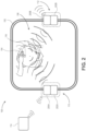
- FIG. 2 illustrates a top, schematic view of the system 100 and the tank 102, according to an example.
- the system 100 may include the tank 102, or may be separate therefrom and configured for use therewith.
- the health sensors 110, 112 may be connected to the side of the tank 102, e.g., clipped to the rim of the tank 102.
- the health sensors 110, 112 may be secured to the tank 102 in any convenient manner, whether releasable or permanently affixed thereto.
- the tank 102 may be fabricated with the health sensors 110, 112 embedded therein.
- the health sensors 110, 112 include Doppler transducers 200A, 200B, respectively, and wireless transceivers 202A, 202B, respectively.
- the wireless transceivers 202A, 202B may be configured for wireless communication (e.g., through the air) with the monitoring device 114.
- at least a portion of the wireless transceivers 202A, 202B may be positioned out of the water 106, e.g., held above the water 106 or otherwise outside of the tank 102.
- any suitable wireless transmission hardware and/or software may be employed for this communication.
- the wireless transceivers 202A, 202B may be replaced with or used in addition to wired communication devices, which may communicate with the monitoring device 114 via one or more cables that are outside of the tank 102.
- the Doppler transducers 200A, 200B may be configured to emit and/or receive ultrasonic Doppler signals in the water 106.
- the Doppler transducers 200A, 200B may each be configured to convert between electrical power signal and Doppler signal in the water 106.
- the Doppler transducers 200A, 200B may be independently steered, as mentioned above and described in greater detail below, such that the Doppler transducers 200A, 200B emit Doppler ultrasonic signals that echo from the mother 104 and are received by the transducers 200A, 200B, permitting acquisition of health data from the mother 104, fetus, or both.
- FIG 3 illustrates a schematic view of a health sensor 300, according to an example.
- the health sensor 300 may be implemented by one or both of the health sensors 110, 112 discussed above.
- the health sensor 300 may include a housing 302, which may be configured to protect components therein from immersion in water.
- a radio transmitter 304 which may be configured to communicate wirelessly with a computing device (e.g., the monitoring device 114 of Figures 1 and 2 ) via an antenna 306.
- the antenna 306 is an external antenna, extending at least partially upwards from the housing 302.
- the antenna 306 may be internal to the housing 302.
- a clip 307 may be secured to the housing 302 and may be configured to connect the housing 302, and thus the health sensor 300, to a rim of a tank (e.g., the tank 102).
- other types of mounting devices may be employed.
- the health sensor 300 may also include a fetal heartrate (FHR) algorithm module 308, which may be positioned within the housing 302.
- the FHR algorithm module 308 may be configured to infer a fetal heartrate from Doppler signals and, e.g., to separate the fetal heartrate signals from maternal heartrate signals.
- the fetal heartrate may be at a different frequency than the maternal heartrate, and thus may be distinguished based on this or any other signal characteristic.
- a Doppler receiver module 310 and a Doppler transmitter section and steering control module 312 may also be included within the housing 302.
- an array e.g., one dimensional, two dimensional, radial, etc.
- the piezoelectric crystals of the array 314 may receive electrical signals from the Doppler transmitter and steering control module 312 and convert these signals to Doppler signals that propagate through the water.
- the crystals of the array 314 may also receive Doppler signals (echoes) from the water and convert them to electric signals.
- the array 314 may be positioned within the housing 302 so as to be at least partially below the surface of the water, thereby permitting the array 314 to transmit Doppler signals and receive echoes directly in the water.
- the array 314 may be steerable, e.g., by changing the orientation of one or more crystals of the array 314, so as to direct the Doppler signals to and receive signals from a desired location.
- the Doppler transmitter section and steering control module 312 may control the directionality of the Doppler signals by adjusting the orientation of the crystals of the array 314, or signaling the array 314 to adjust, e.g., using another actuator.
- the Doppler transmitter section and steering control module 312 may include software configured to control a scan of different orientations for the array 314, so as to direct the Doppler signals.
- Figure 4 illustrates a flowchart of a method 400 for monitoring a health measurement of a mother, a fetus, or both in a water birth, according to an example.
- the method 400 may employ one or more examples of the system 100 discussed above with reference to Figures 1-3 , and is thus described herein with reference thereto. In other examples, however, the method 400 may implement any other heath monitoring system. Further, the steps of the method 400 may be executed in the order presented herein, or in any other order, whether in parallel or in sequence. Additionally, one or more of the steps may be partitioned into two or more steps, and/or any two or more of the steps may be combined into a single step.
- the method 400 may include determining a trajectory for a signal emission from the health sensor(s) 110, 112, which may be submerged in water, as at 402.
- the health sensors 110, 112 may perform a raster scan. In such a raster scan process, the health sensors 110, 112 may transmit in a plurality of different directions, in sequence, and determine which of the directions results in an echo being received. As noted above, this may be controlled by the Doppler transmitter and steering control module 312 of the individual health sensors 110, 112.
- the scanning procedure may stop when an echo is received, or may continue through a predetermined range, and then return to a trajectory that generated useable (e.g., the strongest) echoes representing the desired health measurements.
- the health sensor 110 may orient its transducer(s) in a plurality of different directions until receiving the beacon signal. The health sensor 110 may thus determine the direction for the transducers thereof based at least in part on whether a beacon signal is acquired at any scanned direction. In this latter example, the health sensor 110 may not transmit Doppler signals during the scan, but may rather "listen" for signals from the beacon 116. In other examples, the health sensor 110 may transmit Doppler signals while scanning for beacon 116 signals. Further, in still other examples, the direction for the signals to be emitted may be determined based on other sensors receiving signals from the beacon 116.
- the mother 104 exiting the tank 102 may cause the system 100 to be unable to acquire an echo signal that includes health monitoring information.
- the system 100 may thus be configured such that the health sensors 110, 112 stop looking for an echo after passing through a range of orientations, or may continue to scan until an interrupt is received (e.g., a button pressed, e.g., on the monitor 114, in response to the mother 104 exiting the tank 102).
- the failure to acquire an echo signal may trigger an alarm.
- the method 400 may also include adjusting an orientation of the transducers of the health sensor, as at 404. This adjustment may be based at least in part on the determination made at 402 and may be implemented internal to the individual health sensors 110, 112. In some examples, the determining at 402 and the adjusting at 404 may occur simultaneously, e.g., as part of the same process of orienting the transducers in an appropriate direction. In other examples, for example, the orientation may be determined in 402 and then refined based on a strength of the echoes by further adjusting at 404. In some examples, the steps 402 and 404 may be repeated continuously, at relatively short intervals, or at any time an echo representing a health measurement is not received.
- the method 400 may further include emitting an ultrasonic Doppler signal directly into the water 106 in the trajectory determined at 402, as at 406.
- the health sensor(s) 110, 112 may be at least partially submerged in the water 106, and thus the transducers (e.g., arrays of piezoelectric crystals) may be permitted to communicate directly with the water 106.
- the health sensor(s) 110, 112 may be separated from the mother 104, and may not be connected to the mother 104. As such, the mother 104 may not be tethered to the health sensor(s) 110, 112 via cables.
- the method 400 may also include receiving an echo signal generated in response to the emitted signal, using the health sensor(s) 110 and/or 112, as at 408.
- the echo signal may be received directly from the water 106 by the health sensor(s) 110, 112, which may maintain low attenuation in the echo signal.
- artifacts (noise) in the signal generated by waves or other water movement, echoes from the signal reflecting off the tank 102, etc. may be muted during processing, e.g., based on models of expected data signals (e.g., known characteristics of maternal heartrate, fetal heartrate, and/or uterine activity signals).
- One or more communication signals may then be transmitted (e.g., wirelessly) from the health sensor(s) 110, 112 to the monitoring device 114, as at 410.
- the one or more communication signals may carry data representing the echo signals.
- the health sensor(s) 112, 112 may include an external antenna that may extend out of the water to permit communication of the signals wirelessly to the monitoring device 114.
- the echo signal received by the health sensor(s) 110, 112 may provide data representing one or more health-related properties of the mother and/or fetus. This data may be transmitted (e.g., wirelessly) to the monitoring device 114 for interpretation. That is, the monitoring device 114 may determine one or more health measurements based on the communication signal, which is generated based on the echo signals, as at 412.
- the echo signal may represent a maternal heartrate and/or a fetal heartrate.
- the maternal heartrate and the fetal heartrate may be distinguished, e.g., using the monitoring device 114, based on different characteristics of a maternal heartrate and a fetal heartrate, based on the differences therebetween in frequency, signal strength, or any other signal parameter.
- heartrates for twins, triplets, etc. may be distinguished and, e.g., separately monitored.
- the health sensor(s) 110, 112 and/or the monitoring device 114 may filter and/or process the physiological parameter (e.g., health data) represented by the echo signals, permitting or actively inferring fetal heart rate for transmission via the communication signals.
- the system 100 may include a beacon 116 for locating the mother 104 in the tank 102 and steering the health sensors 110, 112, as noted above in steps 402 and 404.
- the beacon 116 may be coupled to the mother 104 at a reference location.
- the reference location may be selected to coincide with a location of a signal of the fetal heartbeat, and the reference location may remain stationary on the mother 104, while the fetus moves with respect thereto. Such changes in position of the fetus relative to the reference location of the mother 104 may thus provide insight into the progression of the birthing process.
- the method 400 may include receiving the beacon signal from the beacon 116 coupled to the mother 104 at the reference location, as at 414.
- the beacon signals may be ultrasonic, and thus may be acquired by the health sensor(s) 110, 112. Although ultrasonic, the beacon signals may be of a different frequency than (or otherwise distinguishable from) the Doppler signals and/or echoes therefrom.
- the reference location of the beacon 116 may be determined, e.g., using the monitoring device 114 or by communication/coordination between the health sensors 110, 112.
- the location of the fetal heartbeat may also be determined from the echo signals.
- the two locations inferred based on the beacon and echo signals may then be compared so as to determine a location (and/or movement) of the fetus during the birthing process.
- the mother's heartrate signal originates from a fixed location relative to the reference location of the beacon 116. Accordingly, the mother's heartrate may be distinguished based on its location relative to the beacon 116, which may be different from the fetal heartrate source.
- the stationary position of the mother's heart relative to the beacon 116 and the different locations of the mother's heart and the fetal heart(s) may be employed to distinguish between the two signals.
- FIG. 5 illustrates a side, schematic view of another health monitoring system 500, according to an example.
- the health monitoring system 500 may be configured to monitor a health of a mother, fetus within the mother, or both during a water birth.
- the system 500 may generally include a health sensor 502, a converter 504, and a health monitoring device 507. Further, the system 500 may include or be configured for use with a tank 506 that holds water 508.
- the health sensor 502 may be connected directly to the mother via straps, bands, etc., and may be configured to detect maternal heartrate, fetal heartrate, uterine activity, and/or other metrics related to the health of the mother, fetus, or both.
- the health sensor 502 may include one or more ultrasonic transducers configured to send and receive, e.g., Doppler, signals and, in some examples, to process the monitoring signals into communication signals which may be relayed to the converter 504.
- the health sensor 502 may be configured to transmit at least two different "types" of communication signals for reception by the converter 504.
- the different "types" of sensors discussed herein may be radiofrequency or other electromagnetic signals, but with different characteristics, such as frequency band, power, etc.
- the different signal types may be generated by different antenna or by a single antenna, as discussed herein.
- the first signal type may be a BLUETOOTH, WIFI, or MBAN signal, which may be provided for transmission through air to the converter 504.
- the frequency of the first signal type may be 2.4 GHz, 5 GHZ, or a combination thereof. Other frequency spectra may also be employed for such wireless signal transmission through the air.
- the first signal type may be transmitted when the health sensor 502 is above the surface of the water 508.
- the second type of signal may be a relatively low frequency (as compared to the first signal type) signal, suitable for transmission through the water 508.
- the frequency of the second signal may be less than about 1 GHz, less than about 800 MHz, or less than about 600 MHz.
- WMTS or ISM band frequencies may also or instead be used.
- the health sensor 502 may be configured to automatically determine which signal type to use and, in response, activate circuitry configured to transmit data using the selected signal type.
- the health sensor 502 may include a water sensor that detects whether the health sensor 502 is submerged in the water 508, and may generate a submerged signal indicative of whether the health sensor 502 is at least partially submerged.
- a variety of such sensors are known and may be employed.
- changes in impedance in the antenna of the health sensor 502 or other current leakage techniques may be employed to detect when the health sensor 502 is submerged.
- the health sensor 502 may be battery-operated, so as to avoid attaching wires or cords to the mother during the water birth.
- one or more techniques may be employed to conserve the battery of the health sensor 502.
- the health sensor 502 may be configured to transmit a lower power when submerged and using the second signal type, as the distance over which the signal transmits may be expected to be relatively short, e.g., constrained by the dimensions of the tank 506.
- the monitoring signals sent from the health sensor 502 into the mother may be adjusted to prolong battery life.
- the duration of the signal transfer pulses may be dynamically adjusted based on closed-loop monitoring of the signal strength and fetal heartrate. This may account for different depths of the fetal heart, as a function of distance from the health sensor 502 located on the exterior of the mother. For example, a 90 ms signal can be reduced based on a consistent heartbeat detection.
- the system 500 also includes the converter 504.
- the converter 504 serves to receive both of the first and second types of signals from the health sensor 502.
- the converter 504 may be positioned at the surface of the water 508, and may include a first antenna 510 that is configured to receive the first signal type and a second antenna 512 that is configured to receive the second signal type.
- the first antenna 510 may extend upward, above the water 508, and the second antenna 512 may extend downward into the water 508.
- the converter 504 may be buoyant, with the lower end thereof weighted, so as to maintain the second antenna 512 below the surface of the water 508 and the first antenna 510 above the surface.
- the converter 504 may be coupled to the wall of the tank 506.
- the water level may be controlled with respect to the position of the converter 504, or, alternatively, the first antenna 510 may extend to a position above the tank 506 while the second antenna 512 extends to a position proximal to the bottom of the tank 506, e.g., to ensure that the first antenna 510 is not entirely submerged, while the second antenna 512 is at least partially submerged, without regard to the specific water level.
- the converter 504 may be configured to communicate with the health monitoring device 507. As shown, the converter 504 may be configured to communicate with the health monitoring device 507 wirelessly, e.g., through the air via another antenna or via the first antenna 510. In some examples, the converter 504 may also or instead be configured to communicate with the monitor 506 via one or more cables.
- the monitor 506 may be configured to receive data from the converter 504. Further, the health monitoring device 507 may include one or more processors configured to process raw sensor data from the converter 504 into health metrics providing useful information about fetal heartrate, maternal heartrate, uterine activity, and/or other metrics. For example, the health monitoring device 507 may provide a user interface, display, input devices, etc. The health monitoring device 507 may also be configured to make determinations about the health of the mother, fetus, or both, and provide outputs, initiate alarms, etc., based thereon.
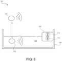
- Figure 6 illustrates a side, schematic view of another example of the system 500.
- the converter 504 and the monitor 506 are integrated into a hub 600.
- the hub 600 may be configured to receive both the first and second signal types and may include the first and second antennae 510, 512. Further, the hub 600 may be configured to convert the data transmitted via the communication signals from the health sensor 502 into health data.
- FIG 7 illustrates a schematic view of the health sensor 502, according to an example.
- the health sensor 502 may include a water sensor 700, a power manager 702, a radio and switch module 704, a first antenna 706, and a second antenna 708. These components may be packaged in a housing 710, which may be configured to survive and protect the components while the housing 710 is submerged in the water 508 (e.g., Figure 5 ).
- the water sensor 700 may be any suitable type of water sensor. Various humidity sensors, water-level sensors, resistivity sensors, impedance sensors, current leakage sensors, etc. are known and may be employed to provide input to the health sensor 502 that permits the health sensor 502 to determine whether it is submerged.
- the power manager 702 may, as noted above, include a battery and may be configured to provide power management functionality to preserve battery life. Accordingly, the power manager 702 may make determinations as to signal transmission strength, e.g., for the communication signals and/or the health monitoring signals that are directed into the mother to detect health metrics. For example, the power manager 702 may dynamically and successively lower signal communication strength in response to the converter 504 (e.g., Figure 5 ) receiving signals. That is, the power manager 702 may reduce signal strength until the converter 504 fails to reliably receive the communication signals. This may apply for the first signal type, the second signal type, or both. Additionally, the power manager 702 may reduce the frequency at which the health monitoring signals are pulsed, the duration of the pulses, or both, e.g., based on the depth of the fetal heartrate, consistency of the measurements, and/or other factors.
- the first antenna 706 may be configured to transmit the first signal type, and the second antenna 708 may be configured to transmit the second signal type. Accordingly, the radio and switch 706 may select which antenna to activate, based on whether the first signal type or the second signal type is to be transmitted.
- the first antenna 706 and the second antenna 708 may be configured to send different signal frequencies, at different power levels, or both. Further, the first antenna 706 may be oriented in a generally upward direction and the second antenna 708 oriented in a generally downward direction, such that partial submersion of the health sensor 502 may result in the first antenna 706 extending out of the water, the second antenna 708 extending in the water, or both.
- the first antenna 706 and the second antenna 708 may be representative of a single, adjustable antenna that may be dynamically configured to transmit in either the frequency of the first signal type or the frequency of the second signal type.
- Figure 8 illustrates a schematic view of the converter 504, according to an example.
- the converter 504 may be configured to receive at least two different types of signals, aggregate the data received in both signal types, and send such aggregated data to the health monitoring device 507, as noted above.
- the converter 504 may include the first antenna 510 and the second antenna 512, as noted above.
- the converter 504 may include a first radio 800 and a second radio 802.
- the first radio 800 may be configured to receive and/or send signals via the first antenna 510
- the second radio 802 may be configured to receive and/or send signals via the second antenna 512.
- the converter 504 may include a housing 806, which may be at least partially water-resistant, such that at least the second antenna 512 may extend below the surface of the water.
- the first antenna 510, the second antenna 512, or both may be external to the housing 506.
- the housing 506 may include one or more structures or devices configured to permit the housing 506 to be attached to the wall of the tank 506 (e.g., Figure 5 ).
- FIG 9 illustrates a schematic view of another health monitoring system 900, according to an example.
- the health monitoring system 900 may include a tank 902 at least partially filled with water 904 for a water birth.
- the health monitoring system 900 may include a health sensor 906, which may be connected to the mother, and may be cordless, so as to permit the mother to move freely into/out of and within the tank 502.
- the device 906 may be configured to transmit signals, and more particularly, may be configured to modulate the signal properties depending on whether the device 906 is submerged in the water 904 or above/out of the water 904, as shown.
- the device 900 may be configured to determine when it is submerged, e.g., using an impedance sensor, as discussed above. In response to determining that the device 906 is not submerged, the device 906 may transmit a signal having a high frequency and power, tailored for air-only transmission and reception at a monitor 910.
- the device 906 may be configured to adaptively modulate the signal and/or frequency so as to ensure an Effective Isotropic Radiated Power (EIRP) link budget is maintained.
- EIRP Effective Isotropic Radiated Power
- Figure 10 illustrates a flowchart of a method 1000 for monitoring a health of a mother, a fetus, or both during a water birth, according to an example.
- the method 1000 may be executed using one or more of the health monitoring systems discussed herein, or others. Accordingly, the method 1000 should not be considered limited to any particular structure, unless otherwise indicated herein. Moreover, it will be appreciated that the steps of the method 1000 may be combined, separated, performed in parallel or in any sequence, without departing from the scope of the present disclosure.
- the method 1000 includes connecting a health sensor 502 to a mother, as at 1002.
- the mother is at least partially submerged in a tank 506 of water 508 while the health sensor 502 is connected to her, e.g., after connecting the sensor 502 to the mother, the mother may enter and at least partially submerge in the water 508.
- the sensor 502 may be secured in any suitable manner, e.g., using straps, bands, etc.
- the method 1000 may also include measuring one or more health metrics of the mother, a fetus within the mother, or both while the mother is at least partially submerged, using the health sensor 502, as at 1004.
- Such monitoring may be accomplished using any type of monitoring device, e.g., ultrasonic transducers such as piezoelectric arrays, as discussed above.
- the method 1000 may further include determining whether the sensor 502 connected to the mother is at least partially submerged, as at 1006. Based on this determination, the method 1000 may select whether to transmit a first signal or a second signal, as at 1008.
- the method 1000 may proceed to transmitting a first signal from health sensor 502 to a converter (e.g., a standalone converter 504 or an integrated hub 600), as at 1010.
- a converter e.g., a standalone converter 504 or an integrated hub 600
- the sensor 502 may activate (power, switch to) circuitry configured to transmit the first signal.
- This first signal may not travel through water without significant attenuation, but may be configured to travel through air.
- the first signal may have a relatively high signal frequency (e.g., 2.5 GHz or 5 GHz). It will be appreciated that the first and second signals may be emitted from the same transmitter, but with one or more parameters altered, e.g., frequency, power, etc.
- the method 1000 may proceed to transmitting a second signal from the health sensor 502 to the converter 504, as at 1012.
- the sensor 502 may activate circuitry configured to transmit the second signal and de-activate (or otherwise not activate) circuitry configured to transmit the first signal.
- the second signal thus travels at least partially through the water to the monitor.
- the second signal may be configured to travel through only water, and thus may be configured to have a relatively low frequency, e.g., 600 MHz, but may employ a relatively low power, as the signal transmission distance may be constrained by the size of the tank 506.
- the second signal may be configured to travel through both water and air, as discussed above, using a specific MBAN signal.
- the device e.g., the device 906 may be configured to adapt the signal to maintain an EIRP link budget.
- the method 1000 may also include receiving the first signals using a first antenna 510 of the monitor 504, as at 1014 and receiving second signals using a second antenna 512 of the monitor 504, as at 1016.
- Two antennae may be used so as to receive the two signals having the two frequencies, although examples are envisioned using a signal antenna.
- the first antenna 510 extends above a surface of the water 508 and a second antenna 512 extends below the surface of the water 508.
- the system 500 includes both a converter 504 and an external health monitoring device 507, which may communicate with one another via a wireless or wired connection.
- the method 1000 may include transmitting one or more communication signals from the converter 504 to the health monitoring device 507, as at 1014.
- the health monitoring device 507 may be configured to provide a user interface, signal processor, etc. so as to facilitate monitoring the health of the mother, fetus, or both.
- the health monitoring device 507 and the converter 504 may be integrated into a hub 700, as discussed above, and thus transmitting to a converter may refer to transmitting to a hub, and vice versa.
- the method 1000 may also include adjusting one or more monitoring parameters implemented by the health sensor 502 (e.g., via an ultrasonic transducer thereof) as it measures data from the mother, fetus, or both, as at 1016.
- the health sensor 502 e.g., via an ultrasonic transducer thereof
- the consistency or distance/depth of the fetal heartrate may be used as a factor to control pulse duration for the ultrasonic signals.
- a variety of other measures may be used, additionally or instead of the foregoing, in order to preserve battery life of the health sensor 502.
- the functions described can be implemented in hardware, software, firmware, or any combination thereof.
- the techniques described herein can be implemented with modules (e.g., procedures, functions, subprograms, programs, routines, subroutines, modules, software packages, classes, and so on) that perform the functions described herein.
- a module can be coupled to another module or a hardware circuit by passing and/or receiving information, data, arguments, parameters, or memory contents.
- Information, arguments, parameters, data, or the like can be passed, forwarded, or transmitted using any suitable means including memory sharing, message passing, token passing, network transmission, and the like.
- the software codes can be stored in memory units and executed by processors.
- the memory unit can be implemented within the processor or external to the processor, in which case it can be communicatively coupled to the processor via various means as is known in the art.
- any of the methods of the present disclosure may be executed by a computing system.
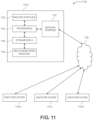
- Figure 11 illustrates an example of such a computing system 1100, in accordance with some examples.
- the computing system 1100 may include a computer or computer system 1101A, which may be an individual computer system 1101A or an arrangement of distributed computer systems.
- the computer system 1101A includes one or more analysis module(s) 1102 configured to perform various tasks according to some examples, such as one or more methods disclosed herein. To perform these various tasks, the analysis module 1102 executes independently, or in coordination with, one or more processors 1104, which is (or are) connected to one or more storage media 1106.
- the processor(s) 1104 is (or are) also connected to a network interface 1107 to allow the computer system 1101A to communicate over a data network 1109 with one or more additional computer systems and/or computing systems, such as 1101B, 1101C, and/or 1101D (note that computer systems 1101B, 1101C and/or 1101D may or may not share the same architecture as computer system 1101A, and may be located in different physical locations, e.g., computer systems 1101A and 1101B may be located in a processing facility, while in communication with one or more computer systems such as 1101C and/or 1101D that are located in one or more data centers, and/or located in varying countries on different continents).
- 1101B, 1101C and/or 1101D may or may not share the same architecture as computer system 1101A, and may be located in different physical locations, e.g., computer systems 1101A and 1101B may be located in a processing facility, while in communication with one or more computer systems such as 1101C and
- a processor can include a microprocessor, microcontroller, processor module or subsystem, programmable integrated circuit, programmable gate array, or another control or computing device.
- the storage media 1106 can be implemented as one or more computer-readable or machine-readable storage media. Note that while in the example of Figure 11 storage media 1106 is depicted as within computer system 1101A, in some examples, storage media 1106 may be distributed within and/or across multiple internal and/or external enclosures of computing system 1101A and/or additional computing systems.
- Storage media 1106 may include one or more different forms of memory including semiconductor memory devices such as dynamic or static random access memories (DRAMs or SRAMs), erasable and programmable read-only memories (EPROMs), electrically erasable and programmable read-only memories (EEPROMs) and flash memories, magnetic disks such as fixed, floppy and removable disks, other magnetic media including tape, optical media such as compact disks (CDs) or digital video disks (DVDs), BLURAY ® disks, or other types of optical storage, or other types of storage devices.
- semiconductor memory devices such as dynamic or static random access memories (DRAMs or SRAMs), erasable and programmable read-only memories (EPROMs), electrically erasable and programmable read-only memories (EEPROMs) and flash memories
- magnetic disks such as fixed, floppy and removable disks, other magnetic media including tape
- optical media such as compact disks (CDs) or digital video disks (DVDs)
- DVDs digital video disks
- Such computer-readable or machine-readable storage medium or media is (are) considered to be part of an article (or article of manufacture).
- An article or article of manufacture can refer to any manufactured single component or multiple components.
- the storage medium or media can be located either in the machine running the machine-readable instructions, or located at a remote site from which machine-readable instructions can be downloaded over a network for execution.
- computing system 1100 contains one or more health monitoring signal module(s) 1108.
- computer system 1101A includes the health monitoring signal module 1108.
- a single health monitoring signal module may be used to perform some or all aspects of one or more examples of the methods.
- a plurality of health monitoring signal modules may be used to perform some or all aspects of methods.
- computing system 1100 is only one example of a computing system, and that computing system 1100 may have more or fewer components than shown, may combine additional components not depicted in the example of Figure 11 , and/or computing system 1100 may have a different configuration or arrangement of the components depicted in Figure 11 .
- the various components shown in Figure 11 may be implemented in hardware, software, or a combination of both hardware and software, including one or more signal processing and/or application specific integrated circuits.
- steps in the processing methods described herein may be implemented by running one or more functional modules in information processing apparatus such as general purpose processors or application specific chips, such as ASICs, FPGAs, PLDs, or other appropriate devices.
- information processing apparatus such as general purpose processors or application specific chips, such as ASICs, FPGAs, PLDs, or other appropriate devices.
- the terms “inner” and “outer”; “up” and “down”; “upper” and “lower”; “upward” and “downward”; “above” and “below”; “inward” and “outward”; and other like terms as used herein refer to relative positions to one another and are not intended to denote a particular direction or spatial orientation.
- the terms “couple,” “coupled,” “connect,” “connection,” “connected,” “in connection with,” and “connecting” refer to “in direct connection with” or “in connection with via one or more intermediate elements or members.”
Landscapes
- Health & Medical Sciences (AREA)
- Life Sciences & Earth Sciences (AREA)
- Engineering & Computer Science (AREA)
- Physics & Mathematics (AREA)
- Veterinary Medicine (AREA)
- Animal Behavior & Ethology (AREA)
- Public Health (AREA)
- Pathology (AREA)
- General Health & Medical Sciences (AREA)
- Biophysics (AREA)
- Biomedical Technology (AREA)
- Heart & Thoracic Surgery (AREA)
- Medical Informatics (AREA)
- Molecular Biology (AREA)
- Surgery (AREA)
- Radiology & Medical Imaging (AREA)
- Nuclear Medicine, Radiotherapy & Molecular Imaging (AREA)
- Gynecology & Obstetrics (AREA)
- Pregnancy & Childbirth (AREA)
- Cardiology (AREA)
- Reproductive Health (AREA)
- Physiology (AREA)
- Acoustics & Sound (AREA)
- Computer Networks & Wireless Communication (AREA)
- Pediatric Medicine (AREA)
- Ultra Sonic Daignosis Equipment (AREA)
- Measuring And Recording Apparatus For Diagnosis (AREA)
Applications Claiming Priority (1)
| Application Number | Priority Date | Filing Date | Title |
|---|---|---|---|
| US17/725,921 US12089984B2 (en) | 2022-04-21 | 2022-04-21 | Health monitoring system for water births |
Publications (2)
| Publication Number | Publication Date |
|---|---|
| EP4265192A1 true EP4265192A1 (de) | 2023-10-25 |
| EP4265192B1 EP4265192B1 (de) | 2025-05-28 |
Family
ID=86226363
Family Applications (1)
| Application Number | Title | Priority Date | Filing Date |
|---|---|---|---|
| EP23167482.1A Active EP4265192B1 (de) | 2022-04-21 | 2023-04-12 | Gesundheitsüberwachungssystem für wassergeburten |
Country Status (3)
| Country | Link |
|---|---|
| US (1) | US12089984B2 (de) |
| EP (1) | EP4265192B1 (de) |
| CN (1) | CN116919464B (de) |
Families Citing this family (1)
| Publication number | Priority date | Publication date | Assignee | Title |
|---|---|---|---|---|
| US12575806B2 (en) | 2024-01-30 | 2026-03-17 | GE Precision Healthcare LLC | Power reduction of fetal ultrasound transducers for extended battery life |
Citations (2)
| Publication number | Priority date | Publication date | Assignee | Title |
|---|---|---|---|---|
| US5865733A (en) * | 1997-02-28 | 1999-02-02 | Spacelabs Medical, Inc. | Wireless optical patient monitoring apparatus |
| CN111820885A (zh) * | 2020-08-26 | 2020-10-27 | 广州三瑞医疗器械有限公司 | 有线无线一体化胎儿监护仪 |
Family Cites Families (12)
| Publication number | Priority date | Publication date | Assignee | Title |
|---|---|---|---|---|
| US20100274145A1 (en) * | 2009-04-22 | 2010-10-28 | Tupin Jr Joe Paul | Fetal monitoring device and methods |
| US9078594B2 (en) | 2010-04-09 | 2015-07-14 | Hitachi, Ltd. | Ultrasound diagnostic and treatment device |
| CN204797887U (zh) * | 2011-12-21 | 2015-11-25 | 莱夫韦弗公司 | 超宽带胎儿监视系统 |
| CA2918793C (en) * | 2012-08-27 | 2018-10-09 | Philip A. Warrick | Method and apparatus for monitoring a fetus during labor |
| WO2015020886A1 (en) * | 2013-08-08 | 2015-02-12 | Gaster Richard S | Wireless pregnancy monitor |
| US9901741B2 (en) | 2015-05-11 | 2018-02-27 | Physio-Control, Inc. | Wearable cardioverter defibrillator (WCD) system using sensor modules with reassurance code for confirmation before shock |
| BR112019009971A8 (pt) * | 2016-11-21 | 2023-03-21 | Evans Mark | Aparelho e método para identificar o nível de risco fetal durante o trabalho de parto, e, método para determinar o nível atual de risco para um feto durante o trabalho de parto e para exibir informações relacionadas e facilitar a identificação do nível de risco fetal durante o trabalho de parto |
| CN108703855B (zh) * | 2018-04-03 | 2020-11-17 | 中国人民解放军北部战区总医院 | 一种妇产科水浴分娩床 |
| US10893559B2 (en) | 2018-05-03 | 2021-01-12 | Apple Inc. | Frequency selection during activity |
| GB2580670B (en) | 2019-01-22 | 2022-06-08 | The Good Birth Company Ltd | Monitoring |
| KR102830354B1 (ko) | 2020-02-03 | 2025-07-04 | 삼성메디슨 주식회사 | 초음파 프로브 |
| WO2022206822A1 (zh) | 2021-04-02 | 2022-10-06 | 深圳市理邦精密仪器股份有限公司 | 胎心多普勒仪及检测方法 |
-
2022
- 2022-04-21 US US17/725,921 patent/US12089984B2/en active Active
-
2023
- 2023-04-07 CN CN202310365675.5A patent/CN116919464B/zh active Active
- 2023-04-12 EP EP23167482.1A patent/EP4265192B1/de active Active
Patent Citations (2)
| Publication number | Priority date | Publication date | Assignee | Title |
|---|---|---|---|---|
| US5865733A (en) * | 1997-02-28 | 1999-02-02 | Spacelabs Medical, Inc. | Wireless optical patient monitoring apparatus |
| CN111820885A (zh) * | 2020-08-26 | 2020-10-27 | 广州三瑞医疗器械有限公司 | 有线无线一体化胎儿监护仪 |
Also Published As
| Publication number | Publication date |
|---|---|
| CN116919464A (zh) | 2023-10-24 |
| EP4265192B1 (de) | 2025-05-28 |
| CN116919464B (zh) | 2026-03-27 |
| US12089984B2 (en) | 2024-09-17 |
| US20230338000A1 (en) | 2023-10-26 |
Similar Documents
| Publication | Publication Date | Title |
|---|---|---|
| EP4265193B1 (de) | Gesundheitsüberwachungssystem für wassergeburten | |
| US12245888B2 (en) | Methods and apparatuses for monitoring fetal heartbeat and uterine contraction signals | |
| CN102046085B (zh) | 光学传感器装置和使用光学传感器装置的方法 | |
| JP7346029B2 (ja) | モバイル超音波システムとの無線超音波プローブのペアリング | |
| JP2013538602A (ja) | バイタルサインを測定するための装置、システム及び方法 | |
| US9198270B2 (en) | Radiographic imaging apparatus with distributed antenna system | |
| EP3039660B1 (de) | Verfahren zur erkennung von gefällen und gefälleerkennungssystem | |
| JP2013533043A5 (de) | ||
| US9635514B2 (en) | Identification of a subject in a facility | |
| WO2016205938A1 (en) | Devices and methods for locating and visualizing underwater objects | |
| EP4265192A1 (de) | Gesundheitsüberwachungssystem für wassergeburten | |
| WO2011109184A1 (en) | Medical system with identification patch | |
| US20190357836A1 (en) | Bladder monitoring system | |
| KR20190057344A (ko) | 태아 모니터링 전자 시스템 | |
| JP2013038501A (ja) | 体内導入型医療装置、医療システムおよび身体情報通信方法 | |
| CN111568468A (zh) | 超声波芯片、超声波检测装置及检测血压的方法 | |
| JPS6134335B2 (de) | ||
| JP2009045179A (ja) | 生体情報通信装置および生体情報監視システム | |
| US11974549B2 (en) | Wireless terminal, livestock monitoring system, and livestock monitoring method | |
| AU2017203224B2 (en) | Device, system and method for monitoring and communicating biometric data of a diver | |
| US11224357B2 (en) | Living body information identification system and method | |
| TW202337388A (zh) | 量測寵物生理訊息的穿戴式裝置及量測方法 | |
| WO2022113632A1 (ja) | 生体情報管理システム | |
| CN112969397A (zh) | 医疗辅助系统 |
Legal Events
| Date | Code | Title | Description |
|---|---|---|---|
| STAA | Information on the status of an ep patent application or granted ep patent |
Free format text: STATUS: REQUEST FOR EXAMINATION WAS MADE |
|
| PUAI | Public reference made under article 153(3) epc to a published international application that has entered the european phase |
Free format text: ORIGINAL CODE: 0009012 |
|
| 17P | Request for examination filed |
Effective date: 20230412 |
|
| AK | Designated contracting states |
Kind code of ref document: A1 Designated state(s): AL AT BE BG CH CY CZ DE DK EE ES FI FR GB GR HR HU IE IS IT LI LT LU LV MC ME MK MT NL NO PL PT RO RS SE SI SK SM TR |
|
| GRAP | Despatch of communication of intention to grant a patent |
Free format text: ORIGINAL CODE: EPIDOSNIGR1 |
|
| STAA | Information on the status of an ep patent application or granted ep patent |
Free format text: STATUS: GRANT OF PATENT IS INTENDED |
|
| INTG | Intention to grant announced |
Effective date: 20241106 |
|
| GRAS | Grant fee paid |
Free format text: ORIGINAL CODE: EPIDOSNIGR3 |
|
| GRAA | (expected) grant |
Free format text: ORIGINAL CODE: 0009210 |
|
| STAA | Information on the status of an ep patent application or granted ep patent |
Free format text: STATUS: THE PATENT HAS BEEN GRANTED |
|
| AK | Designated contracting states |
Kind code of ref document: B1 Designated state(s): AL AT BE BG CH CY CZ DE DK EE ES FI FR GB GR HR HU IE IS IT LI LT LU LV MC ME MK MT NL NO PL PT RO RS SE SI SK SM TR |
|
| REG | Reference to a national code |
Ref country code: GB Ref legal event code: FG4D |
|
| REG | Reference to a national code |
Ref country code: CH Ref legal event code: EP |
|
| REG | Reference to a national code |
Ref country code: IE Ref legal event code: FG4D Ref country code: DE Ref legal event code: R096 Ref document number: 602023003665 Country of ref document: DE |
|
| P01 | Opt-out of the competence of the unified patent court (upc) registered |
Free format text: CASE NUMBER: APP_24099/2025 Effective date: 20250520 |
|
| REG | Reference to a national code |
Ref country code: NL Ref legal event code: MP Effective date: 20250528 |
|
| PG25 | Lapsed in a contracting state [announced via postgrant information from national office to epo] |
Ref country code: FI Free format text: LAPSE BECAUSE OF FAILURE TO SUBMIT A TRANSLATION OF THE DESCRIPTION OR TO PAY THE FEE WITHIN THE PRESCRIBED TIME-LIMIT Effective date: 20250528 Ref country code: ES Free format text: LAPSE BECAUSE OF FAILURE TO SUBMIT A TRANSLATION OF THE DESCRIPTION OR TO PAY THE FEE WITHIN THE PRESCRIBED TIME-LIMIT Effective date: 20250528 |
|
| REG | Reference to a national code |
Ref country code: LT Ref legal event code: MG9D |
|
| PG25 | Lapsed in a contracting state [announced via postgrant information from national office to epo] |
Ref country code: GR Free format text: LAPSE BECAUSE OF FAILURE TO SUBMIT A TRANSLATION OF THE DESCRIPTION OR TO PAY THE FEE WITHIN THE PRESCRIBED TIME-LIMIT Effective date: 20250829 Ref country code: NO Free format text: LAPSE BECAUSE OF FAILURE TO SUBMIT A TRANSLATION OF THE DESCRIPTION OR TO PAY THE FEE WITHIN THE PRESCRIBED TIME-LIMIT Effective date: 20250828 |
|
| PG25 | Lapsed in a contracting state [announced via postgrant information from national office to epo] |
Ref country code: NL Free format text: LAPSE BECAUSE OF FAILURE TO SUBMIT A TRANSLATION OF THE DESCRIPTION OR TO PAY THE FEE WITHIN THE PRESCRIBED TIME-LIMIT Effective date: 20250528 Ref country code: PL Free format text: LAPSE BECAUSE OF FAILURE TO SUBMIT A TRANSLATION OF THE DESCRIPTION OR TO PAY THE FEE WITHIN THE PRESCRIBED TIME-LIMIT Effective date: 20250528 |
|
| PG25 | Lapsed in a contracting state [announced via postgrant information from national office to epo] |
Ref country code: BG Free format text: LAPSE BECAUSE OF FAILURE TO SUBMIT A TRANSLATION OF THE DESCRIPTION OR TO PAY THE FEE WITHIN THE PRESCRIBED TIME-LIMIT Effective date: 20250528 |
|
| PG25 | Lapsed in a contracting state [announced via postgrant information from national office to epo] |
Ref country code: HR Free format text: LAPSE BECAUSE OF FAILURE TO SUBMIT A TRANSLATION OF THE DESCRIPTION OR TO PAY THE FEE WITHIN THE PRESCRIBED TIME-LIMIT Effective date: 20250528 |
|
| PG25 | Lapsed in a contracting state [announced via postgrant information from national office to epo] |
Ref country code: RS Free format text: LAPSE BECAUSE OF FAILURE TO SUBMIT A TRANSLATION OF THE DESCRIPTION OR TO PAY THE FEE WITHIN THE PRESCRIBED TIME-LIMIT Effective date: 20250828 |
|
| PG25 | Lapsed in a contracting state [announced via postgrant information from national office to epo] |
Ref country code: IS Free format text: LAPSE BECAUSE OF FAILURE TO SUBMIT A TRANSLATION OF THE DESCRIPTION OR TO PAY THE FEE WITHIN THE PRESCRIBED TIME-LIMIT Effective date: 20250928 |
|
| PG25 | Lapsed in a contracting state [announced via postgrant information from national office to epo] |
Ref country code: LV Free format text: LAPSE BECAUSE OF FAILURE TO SUBMIT A TRANSLATION OF THE DESCRIPTION OR TO PAY THE FEE WITHIN THE PRESCRIBED TIME-LIMIT Effective date: 20250528 |
|
| REG | Reference to a national code |
Ref country code: AT Ref legal event code: MK05 Ref document number: 1798166 Country of ref document: AT Kind code of ref document: T Effective date: 20250528 |
|
| PG25 | Lapsed in a contracting state [announced via postgrant information from national office to epo] |
Ref country code: DK Free format text: LAPSE BECAUSE OF FAILURE TO SUBMIT A TRANSLATION OF THE DESCRIPTION OR TO PAY THE FEE WITHIN THE PRESCRIBED TIME-LIMIT Effective date: 20250528 Ref country code: AT Free format text: LAPSE BECAUSE OF FAILURE TO SUBMIT A TRANSLATION OF THE DESCRIPTION OR TO PAY THE FEE WITHIN THE PRESCRIBED TIME-LIMIT Effective date: 20250528 Ref country code: SM Free format text: LAPSE BECAUSE OF FAILURE TO SUBMIT A TRANSLATION OF THE DESCRIPTION OR TO PAY THE FEE WITHIN THE PRESCRIBED TIME-LIMIT Effective date: 20250528 |
|
| PG25 | Lapsed in a contracting state [announced via postgrant information from national office to epo] |
Ref country code: CZ Free format text: LAPSE BECAUSE OF FAILURE TO SUBMIT A TRANSLATION OF THE DESCRIPTION OR TO PAY THE FEE WITHIN THE PRESCRIBED TIME-LIMIT Effective date: 20250528 |
|
| PG25 | Lapsed in a contracting state [announced via postgrant information from national office to epo] |
Ref country code: EE Free format text: LAPSE BECAUSE OF FAILURE TO SUBMIT A TRANSLATION OF THE DESCRIPTION OR TO PAY THE FEE WITHIN THE PRESCRIBED TIME-LIMIT Effective date: 20250528 |
|
| PG25 | Lapsed in a contracting state [announced via postgrant information from national office to epo] |
Ref country code: SK Free format text: LAPSE BECAUSE OF FAILURE TO SUBMIT A TRANSLATION OF THE DESCRIPTION OR TO PAY THE FEE WITHIN THE PRESCRIBED TIME-LIMIT Effective date: 20250528 |
|
| PG25 | Lapsed in a contracting state [announced via postgrant information from national office to epo] |
Ref country code: IT Free format text: LAPSE BECAUSE OF FAILURE TO SUBMIT A TRANSLATION OF THE DESCRIPTION OR TO PAY THE FEE WITHIN THE PRESCRIBED TIME-LIMIT Effective date: 20250528 |
|
| REG | Reference to a national code |
Ref country code: DE Ref legal event code: R097 Ref document number: 602023003665 Country of ref document: DE |
|
| PLBE | No opposition filed within time limit |
Free format text: ORIGINAL CODE: 0009261 |
|
| STAA | Information on the status of an ep patent application or granted ep patent |
Free format text: STATUS: NO OPPOSITION FILED WITHIN TIME LIMIT |
|
| REG | Reference to a national code |
Ref country code: CH Ref legal event code: L10 Free format text: ST27 STATUS EVENT CODE: U-0-0-L10-L00 (AS PROVIDED BY THE NATIONAL OFFICE) Effective date: 20260409 |
|
| PGFP | Annual fee paid to national office [announced via postgrant information from national office to epo] |
Ref country code: FR Payment date: 20260320 Year of fee payment: 4 |