EP4265218A1 - Vorrichtungssteuerungssystem und -verfahren, elektronische vorrichtung und speichermedium - Google Patents
Vorrichtungssteuerungssystem und -verfahren, elektronische vorrichtung und speichermedium Download PDFInfo
- Publication number
- EP4265218A1 EP4265218A1 EP20965577.8A EP20965577A EP4265218A1 EP 4265218 A1 EP4265218 A1 EP 4265218A1 EP 20965577 A EP20965577 A EP 20965577A EP 4265218 A1 EP4265218 A1 EP 4265218A1
- Authority
- EP
- European Patent Office
- Prior art keywords
- module
- distance
- magnetic field
- alarm
- control system
- Prior art date
- Legal status (The legal status is an assumption and is not a legal conclusion. Google has not performed a legal analysis and makes no representation as to the accuracy of the status listed.)
- Pending
Links
Images



Classifications
-
- G—PHYSICS
- G01—MEASURING; TESTING
- G01R—MEASURING ELECTRIC VARIABLES; MEASURING MAGNETIC VARIABLES
- G01R33/00—Arrangements or instruments for measuring magnetic variables
- G01R33/20—Arrangements or instruments for measuring magnetic variables involving magnetic resonance
- G01R33/28—Details of apparatus provided for in groups G01R33/44 - G01R33/64
- G01R33/288—Provisions within MR facilities for enhancing safety during MR, e.g. reduction of the specific absorption rate [SAR], detection of ferromagnetic objects in the scanner room
-
- B—PERFORMING OPERATIONS; TRANSPORTING
- B60—VEHICLES IN GENERAL
- B60W—CONJOINT CONTROL OF VEHICLE SUB-UNITS OF DIFFERENT TYPE OR DIFFERENT FUNCTION; CONTROL SYSTEMS SPECIALLY ADAPTED FOR HYBRID VEHICLES; ROAD VEHICLE DRIVE CONTROL SYSTEMS FOR PURPOSES NOT RELATED TO THE CONTROL OF A PARTICULAR SUB-UNIT
- B60W30/00—Purposes of road vehicle drive control systems not related to the control of a particular sub-unit, e.g. of systems using conjoint control of vehicle sub-units
- B60W30/08—Active safety systems predicting or avoiding probable or impending collision or attempting to minimise its consequences
- B60W30/095—Predicting travel path or likelihood of collision
-
- A—HUMAN NECESSITIES
- A61—MEDICAL OR VETERINARY SCIENCE; HYGIENE
- A61B—DIAGNOSIS; SURGERY; IDENTIFICATION
- A61B90/00—Instruments, implements or accessories specially adapted for surgery or diagnosis and not covered by any of the groups A61B1/00 - A61B50/00, e.g. for luxation treatment or for protecting wound edges
- A61B90/06—Measuring instruments not otherwise provided for
-
- B—PERFORMING OPERATIONS; TRANSPORTING
- B60—VEHICLES IN GENERAL
- B60W—CONJOINT CONTROL OF VEHICLE SUB-UNITS OF DIFFERENT TYPE OR DIFFERENT FUNCTION; CONTROL SYSTEMS SPECIALLY ADAPTED FOR HYBRID VEHICLES; ROAD VEHICLE DRIVE CONTROL SYSTEMS FOR PURPOSES NOT RELATED TO THE CONTROL OF A PARTICULAR SUB-UNIT
- B60W50/00—Details of control systems for road vehicle drive control not related to the control of a particular sub-unit, e.g. process diagnostic or vehicle driver interfaces
- B60W50/08—Interaction between the driver and the control system
- B60W50/14—Means for informing the driver, warning the driver or prompting a driver intervention
-
- A—HUMAN NECESSITIES
- A61—MEDICAL OR VETERINARY SCIENCE; HYGIENE
- A61B—DIAGNOSIS; SURGERY; IDENTIFICATION
- A61B90/00—Instruments, implements or accessories specially adapted for surgery or diagnosis and not covered by any of the groups A61B1/00 - A61B50/00, e.g. for luxation treatment or for protecting wound edges
- A61B90/06—Measuring instruments not otherwise provided for
- A61B2090/061—Measuring instruments not otherwise provided for for measuring dimensions, e.g. length
-
- A—HUMAN NECESSITIES
- A61—MEDICAL OR VETERINARY SCIENCE; HYGIENE
- A61B—DIAGNOSIS; SURGERY; IDENTIFICATION
- A61B90/00—Instruments, implements or accessories specially adapted for surgery or diagnosis and not covered by any of the groups A61B1/00 - A61B50/00, e.g. for luxation treatment or for protecting wound edges
- A61B90/08—Accessories or related features not otherwise provided for
- A61B2090/0807—Indication means
-
- B—PERFORMING OPERATIONS; TRANSPORTING
- B60—VEHICLES IN GENERAL
- B60W—CONJOINT CONTROL OF VEHICLE SUB-UNITS OF DIFFERENT TYPE OR DIFFERENT FUNCTION; CONTROL SYSTEMS SPECIALLY ADAPTED FOR HYBRID VEHICLES; ROAD VEHICLE DRIVE CONTROL SYSTEMS FOR PURPOSES NOT RELATED TO THE CONTROL OF A PARTICULAR SUB-UNIT
- B60W50/00—Details of control systems for road vehicle drive control not related to the control of a particular sub-unit, e.g. process diagnostic or vehicle driver interfaces
- B60W50/08—Interaction between the driver and the control system
- B60W50/14—Means for informing the driver, warning the driver or prompting a driver intervention
- B60W2050/143—Alarm means
-
- B—PERFORMING OPERATIONS; TRANSPORTING
- B60—VEHICLES IN GENERAL
- B60W—CONJOINT CONTROL OF VEHICLE SUB-UNITS OF DIFFERENT TYPE OR DIFFERENT FUNCTION; CONTROL SYSTEMS SPECIALLY ADAPTED FOR HYBRID VEHICLES; ROAD VEHICLE DRIVE CONTROL SYSTEMS FOR PURPOSES NOT RELATED TO THE CONTROL OF A PARTICULAR SUB-UNIT
- B60W2510/00—Input parameters relating to a particular sub-units
- B60W2510/18—Braking system
Definitions
- the present disclosure generally relates to the field of device control technologies, and more particularly, to a device control system, a method, an electronic device, and a storage medium applicable to an MR environment.
- Magnetic Resonance Imaging is a widely used medical imaging technique that utilizes the phenomenon of magnetic resonance to obtain electromagnetic signals from the human body and reconstruct information and tomographic images.
- the environment in which MRI is performed is referred to as the Magnetic Resonance (MR) environment.
- MR Magnetic Resonance
- MRI offers advantages such as a variety of imaging modalities and rich information
- its strong magnetic field characteristic also brings certain inconveniences. For instance, there is a risk of magnetization of metallic enclosures in the MR environment.
- embodiments of the present application provide a device control apparatus, method, electronic device, and storage medium applied to the MR environment, which can stop the movement of the device before the device collision and prevent the damage caused by the device collision.
- embodiments of the present application provide a device control system applicable to a Magnetic Resonance (MR) environment, comprising:
- embodiments of the present application provide a device control method applicable to a Magnetic Resonance (MR) environment, comprising:
- embodiments of the present application provide an electronic device, comprising a processor, a memory, a communication interface, and one or more programs; wherein the one or more programs are stored in the memory, when executed by the processor, causing the electronic device to perform the steps in the method as described in the second aspect.
- embodiments of the present application provide a computer-readable storage medium, wherein the computer-readable storage medium stores a computer program, causing a computer to implement the method as described in the second aspect.
- embodiments of the present application provide a computer program product, comprising a non-transitory computer-readable storage medium on which a computer program is stored, the computer program being operable to cause a computer to perform a method as described in the second aspect.
- the magnetic field intensity of the location of the first device is determined by the magnetic field detecting module, and the distance between the first device and the second device is determined by the distance detecting module, and then the risk of the first device being attracted to the second device is determined according to the magnetic field intensity and distance, so that the first device is controlled before the attraction occurs, thereby avoiding collisions between devices, improving the safety of the devices in the MR environment, and preventing losses due to device collisions.
- FIG 1 shows an application scenario of a device control system applicable to a Magnetic Resonance (MR) environment according to an embodiment of the present application.
- MR Magnetic Resonance
- a first device 11 is a movable device with wheels, and the control system 10 is provided in the first device.
- a second device 12 is a non-movable device fixed in the MR environment.
- a distance between the first device 11 and the second device 12 is X, and there is a magnetic field sequentially outwardly decreasing around the second device 12.
- control system 10 can determine a magnetic field intensity at a location of the first device 11 and/or a distance between the first device 11 and the second device 12. The control system 10 further determines a risk level of mutual attraction based on the magnetic field intensity and/or the distance. If the risk level is too high, the control system 10 generates an alarm command, to control the first device 10 to enter a braked state, thereby preventing great damage due to the collision of the first device with the second device.
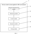
- FIG 2 is a block diagram of a functional module of the device control system applicable to the MR environment according to an embodiment of the present application.
- the device control system 2 applicable to the MR environment is provided in the first device, and the control system 2 includes a magnetic field detecting module 21, a monitoring module 22, and a control module 23, and each module is described separately below.
- control module 23 may include an alarm module and a brake module, to control the first device in conjunction with the multi-level alarm generated by the monitoring module 22.
- the alarm command received by the control module 23 is the first alarm command
- only the alarm module is called for alarming to remind the user to transfer the first device away from the current position.
- both the alarm module and the brake module are called.
- the alarm is performed by the alarm module to remind the user to transfer the first device away from the current position
- the brake is performed by the brake module to put the first device into the braked state so as to prevent the first device from colliding with the second device before the user operates it.
- the device control system 2 further includes an interaction module 24 and a timing module 25.
- the interaction module 24 is configured to receive a release command issued by the user when the first device is in the braked state and send the release command to the brake module.
- the brake module is configured to release the braked state of the first device after receiving the release command, so that the user can transfer the first device away from its current position.
- the timing module 25 is configured to start timing after the braked state of the first device is released. After T seconds, the magnetic field detecting module determines a current magnetic field intensity at the location of the first device. If the current magnetic field intensity is greater than the first threshold value, a lock command is generated and the lock command is sent to the brake module. In this case, it means that the user does not transfer the first device away from the dangerous position after issuing the release command. Therefore, in order to prevent a collision, the timing module 25 issues a lock command to cause the brake module to perform a locking process to lock the wheels of the first device, thereby achieving a secondary protection for the device.
- the device control system 2 further includes an electromagnetic shielding module.
- the electromagnetic shielding module wraps the brake module to shield the influence of electromagnetic field on the brake module, thereby enhancing the reliability of the control system 2.
- the device control apparatus applicable to the MR environment determines the magnetic field intensity at the location of the first device through the magnetic field detecting module, and then determines the risk of the first device being attracted to the second device according to the magnetic field intensity, so as to control the first device before the attraction occurs, thereby avoiding the collision between devices and enhancing the safety of the devices in the MR environment.
- the multi-level alarm command is used to achieve a multi-level control of the first device, thus making the control process more accurate and convenient.
- the first device is further detected twice by the timing module to ensure that the user transfers the first device away from the dangerous position, and the wheels of the first device are locked if the user does not transfer the first device away from the dangerous position, thereby achieving a secondary protection of the device.
- FIG 4 is a block diagram of a functional module of another device control system applicable to the MR environment according to an embodiment of the present application.
- the device control system 4 applicable to the MR environment is provided in the first device, and the control system 4 includes a distance detecting module 41, a monitoring module 42, a control module 43, an interaction module 44 and a timing module 45.
- the specific implementation process of the monitoring module 42, control module 43, interaction module 44 and timing module 45 is similar to that of the monitoring module 22, control module 23, interaction module 24 and timing module 25 of control system 2 in FIG 2 , and will not be repeated herein.
- the distance detecting module 41 will be described as follow.
- the distance detecting module 41 is configured to determine a distance between the first device and a second device.
- the risk level of the first device being attracted to the second device can be determined according to the distance between the first device and the second device.
- any distance measurement method based on electromagnetic correlation will be affected to a certain extent, leading to a decrease in distance measurement accuracy and affecting the control accuracy and efficiency of the control system.
- the distance detecting module 41 may include an infrared emitting module, an infrared receiving module, and a processing module.
- the infrared emitting module is provided at a position on the first device facing the second device and is configured to transmit an infrared light to the second device.
- the infrared receiving module is configured to receive the infrared light reflected by the second device.
- the processing module is configured to determine a distance between the first device and the second device according to an emission time of the infrared emitting module emitting the infrared light to the second device and a reception time of the infrared receiving module receiving the infrared light reflected by the second device.
- the distance between the two devices is determined by determining the time from the emission to the reflection of infrared light.
- the distance detecting module 41 may include a processing module.
- the processing module is specifically configured to: obtain a three-dimensional point cloud space and mark the second device as an origin of the three-dimensional point cloud space; obtain at least one image containing the first device from at least one camera module and determine at least one pixel coordinate of the first device in the at least one image; determine a spatial coordinate of the first device in the three-dimensional point cloud space according to the at least one pixel coordinate and the at least one camera module, and take a distance between the spatial coordinate and the origin as the distance between the first device and the second device.
- the three-dimensional point cloud space is obtained by pre-scanning the real space where the MR environment is located by a simultaneous localization and mapping device. After generating the three-dimensional point cloud space, the second device is set as the origin, and the camera module set in the MR environment is mapped to the corresponding position in the three-dimensional point cloud space.
- the multi-level alarm command is also configured to achieve the multi-level control of the first device.
- the alarm command generated by the monitoring module 42 is the first alarm command
- the first alarm command is configured to raise an alarm to remind the user to transfer the first device away from its current position. This is because there is a risk of attraction to the device at this distance, but the risk level is relatively low. In other words, there is a possibility of being attracted, but the possibility is too low to be negligible. Therefore, there is no need to control the first device, but only to issue an alarm to remind the user to transfer the first device away from its current position.
- the alarm command generated by the monitoring module 42 is a second alarm command, in which the fourth threshold is less than the second threshold.
- the second alarm command is configured to issue the alarm and control the first device to enter the braked state. This is because there is a risk of attraction to the device at this distance, and the risk level is high. In other words, the possibility of being attracted leading to a collision is high, and emergency braking means are required to prevent the device from colliding. Therefore, in addition to issuing an alarm, it is necessary to control the first device to enter a braked state.
- the device control system 4 further includes an electromagnetic shielding module.
- the electromagnetic shielding module wraps around the distance detecting module 41 and the brake module to shield the influence of electromagnetic field on the distance detecting module 41 and the brake module, thereby enhancing the reliability of the control system 2.
- the distance between the first device and the second device is determined by the distance detecting module, and then the risk of the first device being attracted to the second device is determined according to the distance between the first device and the second device, so as to control the first device before the attraction occurs, thereby avoiding the collision between the devices and enhancing the safety of the device in the MR environment.
- the multi-level alarm command is used to achieve the multi-level control of the first device, thereby making the control process more accurate and convenient.
- FIG 5 a block diagram of a functional module of another device control system applicable to the MR environment according to an embodiment of the present application.
- the device control system 5 applicable to the MR environment is provided in the first device, and the control system 5 includes a magnetic field detecting module 51, a distance detecting module 52, a monitoring module 53, a control module 54, an interaction module 55, and a timing module 56.
- the specific implementation process of the magnetic field detecting module 51, the monitoring module 53, the control module 54, the interaction module 55 and the timing module 56 is similar to the specific implementation process of the magnetic field detecting module 21, the monitoring module 22, the control module 23, the interaction module 24 and the timing module 25 of the control system 2 in FIG 2 , and will not be repeated herein.
- the specific implementation process of the distance detecting module 52 is similar to the specific implementation process of the distance detecting module 41 of the control system 2 in FIG 4 , and will not be repeated herein.
- the device control system 5 further includes an electromagnetic shielding module.
- the electromagnetic shielding module wraps around the distance detecting module 52 and the brake module to shield the influence of electromagnetic field on the distance detecting module 52 and the brake module, thereby enhancing the reliability of the control system 2.
- the magnetic field intensity at the location of the first device is determined by the magnetic field detecting module
- the distance between the first device and the second device is determined by the distance detecting module
- the risk of the first device being attracted to the second device is determined according to the magnetic field intensity and the distance between the first device and the second device, forming a double insurance. Therefore, the first device is controlled before the attraction occurs, thereby avoiding collisions between devices and enhancing the safety of the device in the MR environment.
- FIG 6 a structural schematic diagram of a device control apparatus applicable to the MR environment according to an embodiment of the present application.
- the device control apparatus applicable to the MR environment is provided in the first device, and the control device includes a processing unit 61, a Gauss meter 62, a distance sensor 63, a brake module 64, an alarm 65, a tricolor warning light 66, and a digital display 67.
- the processing unit 61 is connected to the Gauss meter 62, the distance sensor 63, the brake module 64, the tricolor warning light 66, and the digital display 67, respectively.
- the alarm 65 is connected to the processing unit 61 through the tricolor warning light 66.
- the alarm 65, tricolor warning light 66 and digital display 67 form an acousto-optical alarm module, and an area where the brake module 64 and the distance sensor 63 are located is an electromagnetic shielded area.
- control unit 6 operates as follows.
- the distance sensor 63 starts working for real-time distance detecting.
- the acquired distance value is greater than DT1 (the warning distance value DT1, when the device is in this position, there is a risk of being attracted, but the risk level is low and no emergency braking means is required)
- the control device does not take any action and the distance sensor 63 continues to work.
- the acquired distance value is less than DT1
- a pre-alarming signal is issued through the acousto-optical alarm module to remind the operator to transfer the device and avoid collision.
- the distance value is further determined. If the distance value is less than DT2 (dangerous distance value DT2, when the device is in this position, there is a risk of being attracted, and the risk level is high, so that the emergency braking means need to be taken to prevent device collision), the brake module 64 is started to brake the first device. If the distance value is greater than DT2, the brake module 64 will not start.
- DT2 angerous distance value DT2
- the Gauss meter 62 also starts to detect the magnetic field intensity in real time.
- GT1 warning magnetic field intensity value
- the control device does not take any action, and the Gauss meter 62 continues to work.
- GT1 warning magnetic field intensity value
- the control device does not take any action, and the Gauss meter 62 continues to work.
- the acquired Gauss meter value is greater than GT1
- a warning alarm signal is issued by through the acousto-optical alarm module to remind the operator to transfer the device and avoid collision.
- the magnetic field intensity value is further determined. If the magnetic field intensity value is greater than GT2 (dangerous magnetic field intensity value GT2, when the device is in this position, there is a risk of being attracted, and the risk level is very high, so that emergency braking means are required to prevent device collision), the brake module 64 is started to brake the first device. If the magnetic field intensity value is less than GT2, the brake module 64 will not start.
- GT2 angerous magnetic field intensity value GT2
- the signal is transmitted to a signal receiver at the brake device. After receiving the signal, the braking device is immediately activated to stop the cart and prevent further collision close to the second device.
- the operator can temporarily release the brake device through the digital display 67 to temporarily release the brake device and move the device away from the dangerous position. After disengagement, the control device is reset.
- the brake device will hold and protect the device twice.
- FIG 8 a flowchart of a device control method applicable to the MR environment according to an embodiment of the present application. As shown in FIG 8 , the device control method applicable to the MR environment includes the following steps.
- a magnetic field intensity at a location of the first device is determined; and/or, a distance between the first device and a second device is determined.
- an alarm command is generated according to the magnetic field intensity and/or the distance.
- the first device is controlled according to the alarm command.
- FIG 9 a structural schematic diagram of an electronic device according to an embodiment of the present application.
- the electronic device 900 includes a transceiver 901, a processor 902, and a memory 903, which are connected to each other through a bus 904.
- the memory 903 is configured to store computer programs and data and can transfer the data stored in the memory 903 to the processor 902.
- the processor 902 is configured to read the computer program in the memory 903 to perform the following operations.
- a magnetic field intensity at a location of the first device is determined; and/or, a distance between the first device and a second device is determined.
- An alarm command is generated according to the magnetic field intensity and/or the distance.
- the first device is controlled according to the alarm command. It should be understood that the specific implementation process of the individual operations performed by the processor 902 shown in FIG 9 can be found in the specific implementation process of the individual modules in the system described in any of FIG 2 , FIG 4 and FIG 5 above, and will not be repeated herein.
- the device control apparatus applicable to the MR environment in the present application may be a smartphone (e.g., Android phone, iOS phone, Windows Phone), a tablet computer, a handheld computer, a laptop computer, a mobile Internet device (MID), a robot or a wearable device, etc.
- the above-mentioned device control apparatus applicable to the MR environment are only examples, not an exhaustive list, which is but not limited to the above-mentioned device control apparatus applicable to the MR environment. In practical applications, the above-mentioned device control apparatus applicable to MR environment may also be an intelligent vehicle terminal or a computer device.
- the present application embodiment further provides a computer-readable storage medium.
- the computer-readable storage medium stores a computer program, and the computer program is executed by a processor to implement some or all of the steps of the device control method applicable to the MR environment as described in the above-method embodiments.
- the storage medium may be a hard disk, a floppy disk, an optical disk, a magnetic tape, a diskette, a thumb drive, a flash memory, etc.
- Embodiments of the present application further provide a computer program product, including a non-transitory computer-readable storage medium storing a computer program, the computer program being operable to cause the computer to perform some or all of the steps of the device control method applicable to the MR environment as described in the above-method embodiments.
- the disclosed apparatuses may be implemented in other ways.
- the above described embodiments of the device are only schematic.
- the division of the units described, is only a logical functional division, and the practical embodiment may be divided in another way. Multiple units or components may be combined or integrated into another system, or some features may be ignored or not implemented.
- the mutual coupling or direct coupling or communication connections shown or discussed may be indirect coupling or communication connections through some interface, device or unit, either electrically or in other forms.
- the units illustrated as separate components may or may not be physically separated, and the components shown as units may or may not be physical units, i.e., may be located in one place or may also be distributed to a plurality of network units. Some or all of these units may be selected according to practical needs to achieve the purpose of the scheme of the embodiments.
- each functional unit in each embodiment of the present application may be integrated in a processing unit, or each unit may be physically present separately, or two or more units may be integrated in a single unit.
- the integrated units may be implemented either in the form of hardware or in the form of software program modules.
- the integrated unit when implemented in the form of a software program module and sold or used as a separate product, may be stored in a computer-readable memory. It is understood that the technical solution of the present application, or that part or all or part of the technical solution which essentially contributes to the prior art, may be embodied in the form of a software product.
- the software product is stored in a memory and includes a number of instructions to enable a computer device (which may be a personal computer, server or network device, etc.) to perform all or part of the steps of the method described in the various embodiments of the present application.
- the above-mentioned memory may be USB flash drive, Read-Only Memory (ROM), Random Access Memory (RAM), removable hard disk, diskette, or CD-ROM, and various other media that can store program code.
- the person having ordinary skill in the art can understand that all or some of the steps in the various methods of the above embodiments may be accomplished by instructing the relevant hardware through a program, which may be stored in a computer-readable memory.
- the memory may be a flash drive, Read-Only Memory (ROM), Random Access Memory (RAM), disk or CD-ROM, etc.
Landscapes
- Engineering & Computer Science (AREA)
- Automation & Control Theory (AREA)
- Health & Medical Sciences (AREA)
- Transportation (AREA)
- Mechanical Engineering (AREA)
- Surgery (AREA)
- Physics & Mathematics (AREA)
- Life Sciences & Earth Sciences (AREA)
- Human Computer Interaction (AREA)
- Condensed Matter Physics & Semiconductors (AREA)
- Medical Informatics (AREA)
- Pathology (AREA)
- Nuclear Medicine, Radiotherapy & Molecular Imaging (AREA)
- General Physics & Mathematics (AREA)
- Biomedical Technology (AREA)
- Heart & Thoracic Surgery (AREA)
- Oral & Maxillofacial Surgery (AREA)
- Molecular Biology (AREA)
- Animal Behavior & Ethology (AREA)
- General Health & Medical Sciences (AREA)
- Public Health (AREA)
- Veterinary Medicine (AREA)
- Magnetic Resonance Imaging Apparatus (AREA)
- Traffic Control Systems (AREA)
Applications Claiming Priority (1)
| Application Number | Priority Date | Filing Date | Title |
|---|---|---|---|
| PCT/CN2020/137404 WO2022126561A1 (zh) | 2020-12-17 | 2020-12-17 | 设备控制系统、方法、电子设备和存储介质 |
Publications (2)
| Publication Number | Publication Date |
|---|---|
| EP4265218A1 true EP4265218A1 (de) | 2023-10-25 |
| EP4265218A4 EP4265218A4 (de) | 2024-02-21 |
Family
ID=82059958
Family Applications (1)
| Application Number | Title | Priority Date | Filing Date |
|---|---|---|---|
| EP20965577.8A Pending EP4265218A4 (de) | 2020-12-17 | 2020-12-17 | Vorrichtungssteuerungssystem und -verfahren, elektronische vorrichtung und speichermedium |
Country Status (3)
| Country | Link |
|---|---|
| US (1) | US12403900B2 (de) |
| EP (1) | EP4265218A4 (de) |
| WO (1) | WO2022126561A1 (de) |
Family Cites Families (14)
| Publication number | Priority date | Publication date | Assignee | Title |
|---|---|---|---|---|
| US6630891B1 (en) * | 2002-05-27 | 2003-10-07 | Emery W. Dilling | Vehicle warning system |
| JP2005192857A (ja) | 2004-01-08 | 2005-07-21 | Toshiba Corp | 核磁気共鳴装置 |
| US8416076B2 (en) * | 2008-04-02 | 2013-04-09 | The Trustees Of Dartmouth College | Magnetic proximity sensor system and associated methods of sensing a magnetic field |
| US8378836B2 (en) * | 2009-11-23 | 2013-02-19 | Kopp Development Inc. | Magnetic field strength threshold alarm |
| US8901928B2 (en) * | 2010-11-09 | 2014-12-02 | Imris Inc. | MRI safety system |
| JP5819688B2 (ja) | 2011-09-16 | 2015-11-24 | ジーイー・メディカル・システムズ・グローバル・テクノロジー・カンパニー・エルエルシー | Mr装置用安全システムおよびmr装置 |
| CN203029261U (zh) * | 2012-08-23 | 2013-07-03 | 上海西门子医疗器械有限公司 | 防碰撞系统及医疗设备 |
| CN204106034U (zh) * | 2014-08-22 | 2015-01-21 | 上海西门子医疗器械有限公司 | 防碰撞的医疗设备 |
| US10082547B2 (en) * | 2015-03-11 | 2018-09-25 | Synaptive Medical (Barbados) Inc. | Operation of the magnet of a magnetic resonance imaging (MRI) system |
| DE102017206310B4 (de) * | 2017-04-12 | 2022-03-10 | Ford Global Technologies, Llc | Fahrassistenzsystem mit Kurzdistanz-Abstandsbestimmung und Betriebsverfahren |
| CN108898815B (zh) * | 2018-07-17 | 2020-08-18 | 上海联影医疗科技有限公司 | 提升医疗设备遥控安全性的方法及控制装置、医疗系统 |
| CN210383915U (zh) * | 2019-05-28 | 2020-04-24 | 新里程医用加速器(无锡)有限公司 | 医用移动床的防碰撞装置和医用扫描系统 |
| EP3748383A1 (de) * | 2019-06-04 | 2020-12-09 | Koninklijke Philips N.V. | Sensorsystem zur erhöhung der sicherheit in mr-umgebungen |
| CN210271137U (zh) * | 2019-06-28 | 2020-04-07 | 应辉志 | 一种用于核磁共振磁体室的警示装置 |
-
2020
- 2020-12-17 WO PCT/CN2020/137404 patent/WO2022126561A1/zh not_active Ceased
- 2020-12-17 EP EP20965577.8A patent/EP4265218A4/de active Pending
-
2023
- 2023-06-16 US US18/336,114 patent/US12403900B2/en active Active
Also Published As
| Publication number | Publication date |
|---|---|
| EP4265218A4 (de) | 2024-02-21 |
| US20230331221A1 (en) | 2023-10-19 |
| US12403900B2 (en) | 2025-09-02 |
| WO2022126561A1 (zh) | 2022-06-23 |
Similar Documents
| Publication | Publication Date | Title |
|---|---|---|
| CN105184214B (zh) | 一种基于声源定位和人脸检测的人体定位方法和系统 | |
| CN109212510A (zh) | 用于测量多线激光雷达的角分辨率的方法和装置 | |
| CN112704568B (zh) | 设备控制系统、方法、电子设备和存储介质 | |
| US11754649B2 (en) | Sensor system for increasing security in MR environments | |
| WO2016199366A1 (ja) | 寸法測定装置および寸法測定方法 | |
| CN102445148A (zh) | 一种获取位置参数的方法、装置及系统 | |
| EP3923184A2 (de) | Verfahren und system zur fahrzeugparkerkennung, elektronisches gerät und speichermedium | |
| US20150141806A1 (en) | Device For The Detection Of Metallic Surgical Articles And Harmonic And RFID Tagging Markers | |
| CN116692690A (zh) | 一种吊车防撞预警方法、装置、设备及介质 | |
| CN104986129A (zh) | 专用车作业状态的监测系统及其方法 | |
| CN105159295B (zh) | 一种x射线无损检测平台协调控制方法 | |
| US12487300B2 (en) | Detection of off-label use of a magnetic resonance imaging coil | |
| US12403900B2 (en) | Collision-avoidance system and method in a magnetizing environment | |
| CN104181544A (zh) | 基于脉冲计数和时间拓展的激光测距方法及系统 | |
| US20190389441A1 (en) | Vehicle control device and management system | |
| CN108136999A (zh) | 对使用机动车的授权 | |
| US10966673B2 (en) | X-ray imaging device, x-ray detector, and x-ray imaging system | |
| US10768330B2 (en) | System and method for locating a marker using a locator with multiple transmitters | |
| US11042988B2 (en) | Boundary detection evaluation | |
| US20240319377A1 (en) | Method for monitoring a loading area | |
| CN113138423A (zh) | 金属检测方法和装置 | |
| WO2021100115A1 (ja) | 対象物検出装置、対象物検出方法、及びプログラム | |
| CN116863434B (zh) | 叉车预警方法、装置、电子设备及计算机可读存储介质 | |
| CN105911543B (zh) | 对运动终端进行无线电测距的方法、装置和系统 | |
| JP2022045758A (ja) | システム、無線通信装置、およびプログラム |
Legal Events
| Date | Code | Title | Description |
|---|---|---|---|
| STAA | Information on the status of an ep patent application or granted ep patent |
Free format text: STATUS: THE INTERNATIONAL PUBLICATION HAS BEEN MADE |
|
| PUAI | Public reference made under article 153(3) epc to a published international application that has entered the european phase |
Free format text: ORIGINAL CODE: 0009012 |
|
| STAA | Information on the status of an ep patent application or granted ep patent |
Free format text: STATUS: REQUEST FOR EXAMINATION WAS MADE |
|
| 17P | Request for examination filed |
Effective date: 20230619 |
|
| AK | Designated contracting states |
Kind code of ref document: A1 Designated state(s): AL AT BE BG CH CY CZ DE DK EE ES FI FR GB GR HR HU IE IS IT LI LT LU LV MC MK MT NL NO PL PT RO RS SE SI SK SM TR |
|
| A4 | Supplementary search report drawn up and despatched |
Effective date: 20240118 |
|
| RIC1 | Information provided on ipc code assigned before grant |
Ipc: G01R 33/48 20060101ALI20240112BHEP Ipc: A61B 90/00 20160101AFI20240112BHEP |
|
| DAV | Request for validation of the european patent (deleted) | ||
| DAX | Request for extension of the european patent (deleted) |