EP4265465B1 - Schleifkontakthalter, schleifkontakt, stromabnehmer und schleifleitungssystem - Google Patents
Schleifkontakthalter, schleifkontakt, stromabnehmer und schleifleitungssystem Download PDFInfo
- Publication number
- EP4265465B1 EP4265465B1 EP23164597.9A EP23164597A EP4265465B1 EP 4265465 B1 EP4265465 B1 EP 4265465B1 EP 23164597 A EP23164597 A EP 23164597A EP 4265465 B1 EP4265465 B1 EP 4265465B1
- Authority
- EP
- European Patent Office
- Prior art keywords
- sliding contact
- contact holder
- holder
- retaining
- slats
- Prior art date
- Legal status (The legal status is an assumption and is not a legal conclusion. Google has not performed a legal analysis and makes no representation as to the accuracy of the status listed.)
- Active
Links
Images

Classifications
-
- B—PERFORMING OPERATIONS; TRANSPORTING
- B60—VEHICLES IN GENERAL
- B60L—PROPULSION OF ELECTRICALLY-PROPELLED VEHICLES; SUPPLYING ELECTRIC POWER FOR AUXILIARY EQUIPMENT OF ELECTRICALLY-PROPELLED VEHICLES; ELECTRODYNAMIC BRAKE SYSTEMS FOR VEHICLES IN GENERAL; MAGNETIC SUSPENSION OR LEVITATION FOR VEHICLES; MONITORING OPERATING VARIABLES OF ELECTRICALLY-PROPELLED VEHICLES; ELECTRIC SAFETY DEVICES FOR ELECTRICALLY-PROPELLED VEHICLES
- B60L5/00—Current collectors for power supply lines of electrically-propelled vehicles
- B60L5/38—Current collectors for power supply lines of electrically-propelled vehicles for collecting current from conductor rails
-
- B—PERFORMING OPERATIONS; TRANSPORTING
- B60—VEHICLES IN GENERAL
- B60L—PROPULSION OF ELECTRICALLY-PROPELLED VEHICLES; SUPPLYING ELECTRIC POWER FOR AUXILIARY EQUIPMENT OF ELECTRICALLY-PROPELLED VEHICLES; ELECTRODYNAMIC BRAKE SYSTEMS FOR VEHICLES IN GENERAL; MAGNETIC SUSPENSION OR LEVITATION FOR VEHICLES; MONITORING OPERATING VARIABLES OF ELECTRICALLY-PROPELLED VEHICLES; ELECTRIC SAFETY DEVICES FOR ELECTRICALLY-PROPELLED VEHICLES
- B60L5/00—Current collectors for power supply lines of electrically-propelled vehicles
- B60L5/18—Current collectors for power supply lines of electrically-propelled vehicles using bow-type collectors in contact with trolley wire
- B60L5/20—Details of contact bow
-
- H—ELECTRICITY
- H01—ELECTRIC ELEMENTS
- H01R—ELECTRICALLY-CONDUCTIVE CONNECTIONS; STRUCTURAL ASSOCIATIONS OF A PLURALITY OF MUTUALLY-INSULATED ELECTRICAL CONNECTING ELEMENTS; COUPLING DEVICES; CURRENT COLLECTORS
- H01R13/00—Details of coupling devices of the kinds covered by groups H01R12/70 or H01R24/00 - H01R33/00
- H01R13/02—Contact members
- H01R13/20—Pins, blades, or sockets shaped, or provided with separate member, to retain co-operating parts together
-
- H—ELECTRICITY
- H01—ELECTRIC ELEMENTS
- H01R—ELECTRICALLY-CONDUCTIVE CONNECTIONS; STRUCTURAL ASSOCIATIONS OF A PLURALITY OF MUTUALLY-INSULATED ELECTRICAL CONNECTING ELEMENTS; COUPLING DEVICES; CURRENT COLLECTORS
- H01R41/00—Non-rotary current collectors for maintaining contact between moving and stationary parts of an electric circuit
Definitions
- the invention relates to a sliding contact holder according to the preamble of claim 1, a current collector according to the preamble of claim 12 and a conductor rail system according to the preamble of claim 13.
- the EP 0 002 627 A1 discloses a brush for the collector of a carriage running in an electrified monorail used in transshipment facilities.
- This brush comprises a base made of insulating material provided with snap-on fastening means firmly connected to electrically conductive elements connected to the collector and in which a projecting part of a sliding contact made of conductive material engages, knife-shaped contact fingers holding the sliding contact.
- the EP 3 333 007 B1 discloses a contact strip for a current collector of a rail vehicle, comprising a first and second strip made of carbon which extend parallel to a longitudinal extension direction and on both sides of a longitudinal extension plane which includes the longitudinal extension direction, further comprising a metal insert which extends along the longitudinal extension direction in the longitudinal extension plane and is provided between the first and second carbon strips, and a current collector carrier to which the first and second carbon strips and the metal insert are mounted.
- the object of the invention is therefore to provide a sliding contact holder, a current collector and a conductor rail system which overcome the above-mentioned disadvantages and provide a current collector design which is as compact and insensitive to vibrations as possible.
- the invention solves this problem by a sliding contact holder with the features of claim 1, a current collector according to the preamble of claim 12 and a conductor rail system according to the preamble of claim 13.
- Advantageous further developments and embodiments of the invention are specified in the subclaims.
- a sliding contact holder as mentioned above is characterized according to the invention in that free ends of the holding lamellae protrude obliquely into the interior space surrounded by the sliding contact holder, wherein adjacent holding lamellae run parallel to one another.
- the free ends of the retaining lamellas can protrude obliquely into the interior space surrounded by the sliding contact receptacle, counter to an insertion direction of the sliding contact into the sliding contact receptacle.
- the free ends of the retaining lamellas can have sharp edges so that they can dig slightly into the sliding contact.
- the retaining lamellas can extend into the interior in a herringbone pattern, in particular arranged one above the other in a height direction of the sliding contact holder or next to one another in the feed direction or insertion direction of the sliding contact or the height direction of the sliding contact holder, so that due to the large number of retaining lamellas arranged one above the other or next to one another, a secure fit is ensured, and that even if a small number of retaining lamellas are damaged, the fit in the sliding contact holder is still ensured. Free ends of the retaining lamellas can preferably be designed to rest on the sliding contact.
- the retaining lamellas can advantageously be arranged on at least one side wall of the interior of the sliding contact holder, which is advantageous in terms of manufacturing technology. If necessary, additional retaining lamellas protruding into the interior can be arranged on a side wall of the interior of the sliding contact holder opposite the at least one side wall, which can improve the fit.
- the retaining lamellas can run in a direction parallel to the longitudinal direction of the sliding contact contacting the conductor line, so that the retaining lamellas are pressed to the side when the sliding contact is inserted into the sliding contact receptacle and are thereby tensioned in order to act on the walls of the sliding contact against the insertion direction when the sliding contact is pulled out.
- the retaining lamellas can run in a direction parallel to the direction in which the sliding contact is inserted into the sliding contact holder.
- the retaining lamellas are pushed away to the side when the sliding contact is inserted and are pressed against the walls of the sliding contact in order to provide resistance when the sliding contact is pulled out.
- the distance between retaining slats arranged on opposite sides of the interior or between one side of the interior and retaining slats arranged on the opposite side of the interior can preferably be smaller than the width of the insertion area transversely to and/or in the longitudinal direction.
- the sliding contact holder and/or the holding lamellas can consist of an electrically conductive material in order to provide the simplest and best possible electrical connection between the sliding contact and the sliding contact holder.
- the retaining lamellas are elastic or have elastic properties in order to be able to fit onto the sliding contact or dig into it as well and permanently as possible.
- the retaining lamellas can also be made of a material that is harder than the material from which the sliding contact is made, which allows the retaining lamellas to dig into the sliding contact even better and ensure a secure hold.
- the sliding contact holder and the holding lamellas can be formed in one piece, so that on the one hand good electrical conduction without contact resistance and on the other hand simple production is possible. In addition, there is then no risk of the holding lamellas coming loose from the sliding contact holder and the sliding contact no longer being held securely in the sliding contact holder.
- the sliding contact holder can preferably consist of an electrically conductive material.
- the sliding contact holder can consist of an electrically insulating material, in particular plastic, with the holding lamellas then preferably consisting of an electrically conductive material and preferably being electrically connected to the sliding contact connection. This allows the sliding contact holder to electrically insulate the sliding contact from the outside, while the holding lamellas can preferably be cast into the sliding contact holder, which simplifies the manufacture of the sliding contact holder.
- a current collector as mentioned at the outset is characterized according to the invention in that the sliding contact holder is or are designed as described above and below.
- the use of such a current collector enables short set-up times and maintenance times for the use of new sliding contacts, in particular when replacing worn sliding contacts.
- a conductor rail system as mentioned above is characterized according to the invention in that the current collector is designed as described above and below.
- Such a conductor rail system allows the quick and easy replacement of worn and/or defective sliding contacts.
- the longitudinal direction of the conductor rail can correspond to the longitudinal extension of the sliding contact inserted into the sliding contact holder.
- the insertion direction of the sliding contact into the sliding contact holder can advantageously be perpendicular to the longitudinal direction and/or perpendicular to the transverse extension of the sliding contact or perpendicular to a transverse direction which runs perpendicular to the longitudinal direction and to a feed direction of the sliding contact to the conductor rail.
- essentially parallel does not mean mathematically exact parallelism, but also minor deviations from parallelism by a few degrees, which, for example, are not exactly straight or mounted conductor rails or for other reasons.
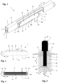
- Fig. 1 shows a partially broken three-dimensional oblique view of a conductor rail system 1 according to the invention with a conductor rail 2 known per se running in a longitudinal direction L.
- a conductor rail 2 known per se running in a longitudinal direction L.
- several such conductor rails 2 can be arranged next to one another, but for reasons of clarity the invention is only described here with reference to one conductor rail 2.
- the conductor rail 2 has a conductor profile 3 with a trough-shaped grinding section 4 made of an electrically conductive material. Depending on the application and in particular the level of the electrical current to be transmitted, the entire conductor profile 3 can also be made of an electrically conductive material or a combination of different electrically conductive materials.
- the busbar 4 is surrounded by an insulating profile 5 made of an electrically insulating material and serves, among other things, as contact protection for operating personnel and to prevent earth faults and, in the case of several conductor rails 2 arranged next to one another, conductor short circuits between the busbars of the conductor rails 2 arranged next to one another. On the Fig.
- the conductor rail 2 On the downward-facing side, the conductor rail 2, and in particular also the insulating profile 5 and the conductor profile 3, has a longitudinal slot 6 running in the longitudinal direction L.
- the above design is basically known to the person skilled in the art and does not require any in-depth explanation.
- a current collector 7 is provided, only partially shown in the drawings. Other parts of the current collector 7 that are not shown, such as a feed device for moving and permanently holding against the conductor line 2 or means for fastening to the electrical consumer, have been omitted for reasons of clarity and are otherwise known to the person skilled in the art.
- the current collector 7 has a sliding contact 8 with a sliding area 8a, which can be moved in a feed direction Z through the longitudinal slot 6 to the sliding section 4 and constantly pressed against it in order to make electrical contact with the trough-shaped sliding section 4 of the conductor profile 3 by means of a feed device (not shown).
- a feed device not shown
- the sliding contact 8 is brought into contact with the conductor profile 4 through the longitudinal slot 6 of the insulating profile 3 for making electrical contact with the trough-shaped sliding section 15.
- the sliding contact 8 has an insertion area 8b, with which the sliding contact 8 can be inserted in the feed direction Z from the top of the drawings into an interior space 9a of a correspondingly designed sliding contact receptacle 9 of the current collector 7.
- the insertion area 8b is preferably narrower than the sliding area 8a in a transverse direction Q running transversely to the longitudinal direction L and the feed direction Z.
- the two areas 8a, 8b can also have the same width or other width ratios.
- the sliding contact holder 9 has side walls 10, 10' running in the longitudinal direction L and spaced apart from one another in the transverse direction Q, as well as front walls 11, 11' which laterally surround the interior space 9a.
- the side walls 10, 10' On their inner sides facing each other, i.e. the sides facing the interior 9a of the sliding contact receptacle 9, the side walls 10, 10' have, particularly in Fig. 3 and 4 clearly visible retaining slats 12, 12' running in the longitudinal direction L.
- the holding lamellae 12, 12' run at an angle to the interior 9a, inclined from top to bottom in the direction of a base 13 of the interior 9a of the sliding contact holder 9, i.e. in the feed direction Z away from the sliding area 8a and, during operation, therefore also away from the conductor line 2.
- the holding lamellae 12, 12' are therefore also inclined downwards away from the locking projections 17, 17'.
- the arrangement of the holding lamellae 12, 12' one above the other in the height direction Z can also be described as herringbone-like, in particular with regard to the cross-section transverse to the longitudinal direction L and the height direction Z.
- a width W of the insertion area 8b of the sliding contact 8 in the transverse direction Q is slightly wider than the distance between the front edges of opposite, relaxed holding lamellae 12, 12' in the transverse direction Q.
- the holding lamellae 12, 12' are somewhat elastic or yielding and can thus be pushed slightly to the side by the insertion area 8b when the sliding contact 8 is inserted into the sliding contact receptacle 9. Due to this elasticity, the front edges of the holding lamellae 12, 12' are then pressed against the long sides of the sliding contact 8 in the insertion area 8b and dig into it slightly. This prevents the sliding contact 8 from falling out of the sliding contact receptacle 9 during normal operation.
- the holding lamellas 12, 12' preferably have sharp front edges to facilitate digging into the sliding contact 8 and to ensure the electrical connection between the two parts.
- the holding lamellae 12, 12' are made of a material that is somewhat harder than the material of the sliding contact 8 or the insertion area 8b.
- the sliding contact 8 can preferably be made of a material that is a good electrical conductor, for example aluminum, copper or graphite or corresponding mixtures, so that the holding lamellae 12, 12' are preferably made of a material that is harder than the material.
- the sliding contact receptacle 9 and thus also the holding lamellas 12, 12' are made of an electrically conductive material, which, due to the firm attachment and the partial digging of the holding lamellas 12, 12' into the insertion area 8b of the sliding contact 8, establishes a good electrically conductive connection to the latter.
- the sliding contact receptacle 9 is itself accommodated in a sliding contact holder 14, which is made of an electrically insulating material.
- the sliding contact holder 14 has a box-shaped design with two side walls 15, 15' running essentially parallel to one another in the longitudinal direction L, which, together with front walls 16, 16', surround an interior space for accommodating the sliding contact receptacle 9.
- Fig. 1 to 4 At the upper end of the side walls 15, 15' and the front walls 16, 16', inwardly projecting longitudinal locking projections 17, 17' and front locking projections 18, 18' are provided, which completely surround the sliding contact receptacle 9 at the top. If necessary, the longitudinal locking projections 17, 17' or front locking projections 18, 18' can also be omitted.
- the side walls 15, 15' and the locking projections 17, 17' surround the sliding contact receptacle 9 together with the corresponding front side walls 16, 16' and locking projections 18, 18'.
- the sliding contact receptacle 9 is firmly cast into the sliding contact holder 14, i.e. it is additionally held on all four sides at the upper end by the locking projections 17, 17', 18, 18 ⁇ .
- the sliding contact holder 14 also serves as contact protection.
- the sliding contact holder 9 has a sliding contact connection 19 on the side facing away from the conductor line 2.
- the sliding contact connection 19 is firmly and electrically conductively connected to the base of the sliding contact holder 9, and preferably both parts are made of one material, particularly preferably in one piece. However, different parts and electrically conductive materials can also be used.
- connection connection 19 is surrounded by a connection element 20 of the sliding contact holder 14, wherein the connection element 20 serves as additional insulation and has plug connection connections and/or elements which are provided for corresponding plug elements of a connection connection to the electrical consumer.
- two circular recesses 21, 21' are provided through the sliding contact 8 for a pulling tool with two corresponding engagement pins, which can preferably be arranged on a common handle. These are then inserted into the recesses 21, 21' and the sliding contact 8 is then pulled out of the sliding contact holder 9 with gentle force.
- the recesses can also have a different cross-section, for example a triangular, quadrangular, pentagonal, hexagonal or polygonal cross-section. If necessary, the recesses may not pass completely through the sliding contact 8, but may merely be depressions provided on one and/or both long sides of the sliding contact 8, into which a gripping tool engaging in one and/or more depressions on both long sides can engage.
- FIG. 5 to 8 The embodiment shown differs essentially in the design of the alternative sliding contact holder 22. How well in Fig. 8 As can be seen, an interior space 22a of the sliding contact holder 22 has side walls 23, 23' running in the longitudinal direction L in the feed direction Z, i.e. the height direction of the sliding contact holder 22 extending retaining slats 24, 24', in contrast to the retaining slats 12, 12' extending in the longitudinal direction L of the Fig. 1 to 4 shown and described above.
- the retaining slats 24, 24' are manufactured in accordance with the retaining slats 12, 12' described above, i.e. formed from the material of the side walls 23, 23'. However, they can also be attached to the side walls 23, 23' and/or possibly consist of a different material.
- the distance between opposite, relaxed holding lamellae 24, 24' is again somewhat smaller than the width W of the insertion area 8b of the sliding contact 8, so that the elastic holding lamellae 24, 24' give way again somewhat when the sliding contact 8 is inserted and are thereby tensioned and then dig or claw slightly into the insertion area 8.
- the holding lamellae 24, 24' run parallel to one another.
- the free front ends of the holding lamellae 24, 24' are preferably provided with a sharp edge in order to be able to dig better into the insertion area 8b of the sliding contact 8.
- the retaining lamellae 24, 24 ⁇ protrude from the respective side walls 23, 23' again obliquely into the interior 22a of the sliding contact receptacle 22.
- the free front ends of the retaining lamellae 24, 24 ⁇ point in the same direction on both side walls 23, 23', i.e. from a Fig. 6 to 7 left front side wall 25' to the right front side wall 25.
- the advantage of the alternative sliding contact holder 22 compared to the sliding contact holder 9 described above is that when the sliding contact 8 is pulled out, the retaining lamellas 24, 24' running in the feed direction Z are not bent upwards against their inclined position, so that the risk of damage or tearing off of one of the retaining lamellas 12, 12' or even part or all of the insertion area 8b of the sliding contact 8 can be avoided.
- the sliding contact 8 is held securely in the sliding contact holder 22 by the retaining lamellas 24, 24', since the retaining lamellas 24, 24' also rest against the sliding contact 8 in a spring-elastic manner and, due to the main direction of movement of the current collector 7 in the longitudinal direction L, preferably brace themselves against the direction of movement when the sliding contact 8 is in Fig. 5 to 8 moves to the left.
- this design is particularly advantageous if the electrical consumer with the current collector always moves in the same direction in the longitudinal direction L, as is common, for example, in the case of electric overhead rail systems in the area of production lines.
- the current collectors usually always move in the same direction along the production line during normal operation, so that the use of the current collectors in Fig. 5 to 8 shown alternative sliding contact holder 22 is particularly advantageous.
- the holding lamellas 24, 24 ⁇ can then preferably be directed against the direction of travel, so that the sliding contact 8 is constantly pressed against the front edges of the holding lamellas 24, 24' during travel and is thus held well in the sliding contact holder 9.
- the retaining lamellas 24, 24' can advantageously also be bevelled in opposite directions, i.e. in Fig. 5 to 8 on one side wall 23 to the right and on the opposite side wall 23' to the left.
- the sliding contact 8 is pressed at least against the edges of the holding slats 24 and 24' pointing against the direction of travel when moving in both directions.
- the distance between their front edges is preferably somewhat smaller than the width W of the sliding contact 8 and in particular of the insertion area 8b in the transverse direction Q, so that when the sliding contact 8 is inserted into the sliding contact receptacle 9 or 22, a good mechanical hold as well as a good electrical connection can be established between the sliding contact receptacle 9 or 22 and the holding slats 12, 12' or 24, 24'.
- the sliding contact receptacles 9, 22 may not be cast in firmly, but rather inserted into the sliding contact holder 9 from above. For this purpose, it is then advantageous not to provide any locking projections 18, 18 ⁇ on the front and rear end faces 16, 16' in the longitudinal direction.
- the sliding contact receptacles 9, 22 can then be inserted into the sliding contact holder 14 from above if designed accordingly, in particular if the side walls 8, 8 ⁇ and 18, 18 ⁇ of the sliding contact receptacles 9 and 22 can be moved somewhat elastically towards one another.
- the front side side walls 11, 11' and 25, 25' running in the transverse direction Q are preferably omitted in the sliding contact receptacles 9 and 22, so that a U-profile shape essentially results when viewed from the longitudinal direction L.
- the sliding contact receptacles 9 and 22 can also be designed directly as sliding contact holders 14, so that no additional side walls 15, 15', 16, 16' surrounding the sliding contact receptacles 9 and 22 are required. This is particularly the case when, at low voltage levels or due to the installation situation, electrical insulation of the sliding contact 8 by the sliding contact holder 14 is not necessary.
- the manufacture of the sliding contact holder 14 can then be simplified even further, since it can then be formed directly from the sliding contact receptacles 9 and 22.
- retaining lamellas 12, 12' or 24, 24' shown in the drawings a smaller number can also be used, and their design can also be different.
- a triangular configuration can also be used, in which the tips of the triangles point towards each other and towards the side walls of the sliding contact 8, 8'.
- a trapezoidal cross-section or a circular section can also be used.
- the retaining lamellas have relatively sharp edges, as in the design described in detail above as herringbone-like retaining lamellas or with a triangular cross-section.
- retaining slats 12, 12' or 24, 24' may be provided on only one of the side walls 10, 10' or 23, 23'. The distance between these retaining slats 12, 12' or 24, 24' and the opposite side wall 10, 10' or 23, 23' is then again somewhat smaller than the width W of the insertion area 8b.
- the arrangements can be made according to the Figures 1 to 4 or 5 to 8 can also be combined, for example in that holding slats 12 running in the longitudinal direction L on one of the side walls 10, 10' or 23, 23' and holding slats 24 running in the insertion direction Z on the opposite side wall 10', 10 or 23', 23.
- the orientation of the holding slats 12, 12' or 24, 24' can also be changed in sections on one or both side walls 10', 10 or 23', 23 in the longitudinal direction L.
- retaining lamellas can be arranged or formed on the front walls 11, 11' of the interior 9a or 22a of the sliding contact receptacle 9 or 22, which are otherwise designed like the retaining lamellas 12, 12' or 24, 24' described above.
- the distance between the unloaded front retaining lamellas 11, 11' is then again somewhat smaller than the length of the insertion area 8b in the longitudinal direction L.
- the combinations of different orientations of the retaining lamellas described above can be adopted, for example, the front retaining lamellas can run in the insertion direction Z, while the retaining lamellas 12, 12' on the side walls 10', 10 run in the longitudinal direction L. It is also conceivable that retaining lamellas are provided only on one, two, three or all sides 15, 15', 16, 16 ⁇ of the sliding contact holder 9 or 22.
- the longitudinal side walls of the sliding contact 8 running in the longitudinal direction L can also taper downwards in the insertion area 8b, so that the side walls 10, 10' or 23, 23 ⁇ of the sliding contact receptacle 9 or 22 also taper downwards accordingly and/or at least the retaining lamellae 12, 12' extend further inwards downwards.
- This can simplify the insertion of the insertion area 8b of the sliding contact 8 into the sliding contact receptacle 9.
- the retaining slats 12, 12' can be interrupted in the longitudinal direction L, wherein adjacent retaining slats 12, 12' can advantageously be interrupted at different locations in the longitudinal direction L.
Landscapes
- Engineering & Computer Science (AREA)
- Power Engineering (AREA)
- Transportation (AREA)
- Mechanical Engineering (AREA)
- Connector Housings Or Holding Contact Members (AREA)
- Current-Collector Devices For Electrically Propelled Vehicles (AREA)
Description
- Die Erfindung betrifft einen Schleifkontakthalter nach dem Oberbegriff des Anspruchs 1 einen Stromabnehmer nach dem Oberbegriff des Anspruchs 12 sowie ein Schleifleitungssystem nach dem Oberbegriff des Anspruchs 13.
- Aus dem Stand der Technik sind Stromabnehmer mit Schleifkontakthaltern bekannt, in die in der Regel fest in die Schleifkontakthalter eingebundene Schleifkontakte enthalten sind. Hierdurch kann eine gute elektrische Verbindung zwischen einem Schleifkontaktanschluss des Stromabnehmers und dem Schleifkontakt, welcher in eine Stromschiene des Schleifleitungssystems eingreift, hergestellt werden. Nachteilig ist j edoch, dass bei abgenutzten Schleifkontakten stets der Schleifkontakthalter gemeinsam mit dem Schleifkontakt ausgetauscht werden muss, wobei der Schleifkontakthalter in der Regel fest an einem entsprechenden Haltemechanismus des Stromabnehmers befestigt ist, beispielsweise angeschraubt.
- Die
EP 0 002 627 A1 offenbart eine Bürste für den Kollektor eines Wagens, der in einer elektrifizierten Einschienenbahn fährt, die in Umschlaganlagen eingesetzt wird. Diese Bürste umfasst einen Sockel aus isolierendem Material, der mit Schnappbefestigungsmitteln ausgestattet ist, die fest mit elektrisch leitenden Elementen verbunden sind, die mit dem Kollektor verbunden sind und in die ein vorstehendes Teil eines Schleifkontakts aus leitendem Material eingreift, wobei messerförmige Kontaktfinger den Schleifkontakt halten. - Die
EP 3 333 007 B1 offenbart eine Schleifleiste für einen Stromabnehmer eines Schienenfahrzeugs, umfassend eine erste und zweite Leiste aus Kohlenstoff, die sich parallel zu einer Längserstreckungsrichtung und beiderseits einer Längserstreckungsebene, welche die Längserstreckungsrichtung umfasst, erstrecken, weiter umfassend einen Metalleinsatz, der sich entlang der Längserstreckungsrichtung in der Längserstreckungsebene erstreckt und zwischen der ersten und zweiten Kohlenstoffleiste vorgesehen ist, und einen Stromkollektorträger, an dem die erste und zweite Kohlenstoffleiste und der Metalleinsatz angebaut sind. - Aufgabe der Erfindung ist es deshalb, einen Schleifkontakthalter, einen Stromabnehmer sowie ein Schleifleitungssystem bereitzustellen, welche die oben genannten Nachteile überwinden und eine möglichst kompakte und schwingungsunempfindliche Ausgestaltung des Stromabnehmers bereitstellen.
- Die Erfindung löst diese Aufgabe durch einen Schleifkontakthalter mit den Merkmalen des Anspruchs 1, einen Stromabnehmer nach dem Oberbegriff des Anspruchs 12 sowie ein Schleifleitungssystem nach dem Oberbegriff des Anspruchs 13. Vorteilhafte Weiterbildungen und Ausgestaltungen der Erfindung sind in den Unteransprüchen angegeben.
- Ein eingangs genannter Schleifkontakthalter ist erfindungsgemäß dadurch gekennzeichnet, dass freie Enden der Haltelamellen schräg in den von der Schleifkontaktaufnahme umgebenen Innenraum ragen, wobei benachbarte Haltelamellen zueinander parallel verlaufen.
- Bevorzugt können die freien Enden der Haltelamellen entgegen einer Einsteckrichtung des Schleifkontakts in die Schleifkontaktaufnahme schräg in den von der Schleifkontaktaufnahme umgebenen Innenraum ragen.
- Um einen verbesserten Sitz des Schleifkontakts im Schleifkontakthalter zu gewährleisten, können die freien Enden der Haltelamellen scharfkantig sein, so dass sie sich etwas in den Schleifkontakt eingraben können.
- Bevorzugt können die Haltelamellen fischgrätartig in den Innenraum ragen, insbesondere also in einer Höhenrichtung der Schleifkontaktaufnahme übereinander oder in der Zustellrichtung bzw. Einsteckrichtung des Schleifkontakts bzw. der Höhenrichtung der Schleifkontaktaufnahme nebeneinander angeordnet sind, so dass aufgrund der Vielzahl von übereinander oder nebeneinander angeordneten Haltelamellen zum einen ein sicherer Sitz gewährleistet ist, und dass bei einer kleinen Anzahl von beschädigten Haltelamellen dennoch der Sitz in der Schleifkontaktaufnahme gewährleistet ist. Bevorzugt können freie Enden der Haltelamellen zur Anlage an den Schleifkontakt ausgebildet sein.
- Weiter können vorteilhaft die Haltelamellen auf mindestens einer Seitenwandung des Innenraums der Schleifkontaktaufnahme angeordnet sein, was fertigungstechnisch günstig ist. Ggf. können zusätzlich auf einer der mindestens einen Seitenwandung gegenüberliegenden Seitenwandung des Innenraums der Schleifkontaktaufnahme weitere in den Innenraum ragende Haltelamellen angeordnet sein, wodurch der Sitz verbessert werden kann.
- Bevorzugt können die Haltelamellen in eine zur Längsrichtung des die Schleifleitung kontaktierenden Schleifkontakts parallelen Richtung verlaufen, so dass die Haltelamellen beim Einstecken des Schleifkontakts in die Schleifkontaktaufnahme zur Seite gedrückt und dabei gespannt werden, um beim Herausziehen des Schleifkontakts an den Wandungen des Schleifkontakts gegen die Einsteckrichtung wirken.
- Weiter können die Haltelamellen in einer zur Einsteckrichtung des Schleifkontakts in die Schleifkontaktaufnahme parallelen Richtung verlaufen. Auch hierbei werden die Haltelamellen beim Einstecken des Schleifkontakts seitlich weggedrückt und dabei gegen die Wandungen des Schleifkontakts gedrückt, um dem Herausziehen des Schleifkontakts einen Widerstand entgegenzusetzen.
- Weiter kann bevorzugt bei nicht eingestecktem Schleifkontakt der Abstand zwischen auf einander gegenüberliegenden Seiten des Innenraums angeordneten Haltelamellen oder zwischen einer Seite des Innenraums und auf der gegenüberliegenden Seite des Innenraums angeordneten Haltelamellen kleiner sein als die Breite des Einsteckbereichs quer zur und/oder in Längsrichtung.
- Bevorzugt können die Schleifkontaktaufnahme und/oder die Haltelamellen aus einem elektrisch leitfähigen Material bestehen, um so eine möglichst einfache und gute elektrische Verbindung zwischen Schleifkontakt und Schleifkontaktaufnahme bereitzustellen.
- Um einen verbesserten Sitz des Schleifkontakts im Schleifkontakthalter zu ermöglichen, sind die Haltelamellen elastisch bzw. weisen elastische Eigenschaften auf, um sich möglichst gut und dauerhaft an den Schleifkontakt anlegen bzw. in diesen eingraben zu können. Bevorzugt können die Haltelamellen weiter aus einem Material bestehen, welches härter ist als das Material, aus dem der Schleifkontakt besteht, wodurch sich die Haltelamellen noch besser in den Schleifkontakt eingraben und einen sicheren Halt gewährleisten können.
- In einer vorteilhaften Weiterbildung können die Schleifkontaktaufnahme und die Haltelamellen einstückig ausgebildet sein, so dass zum einen eine gute elektrische Durchleitung ohne Übergangswiderstand und zum anderen eine einfache Fertigung möglich ist. Zudem besteht dann keine Gefahr, dass sich die Haltelamellen von der Schleifkontaktaufnahme lösen und der Schleifkontakt nicht mehr sicher in der Schleifkontaktaufnahme gehalten wird. Bevorzugt kann der Schleifkontakthalter aus einem elektrisch leitfähigen Material bestehen. Alternativ kann der Schleifkontakthalter aus einem elektrisch isolierenden Material, insbesondere Kunststoff bestehen, wobei die Haltelamellen dann bevorzugt aus einem elektrisch leitfähigen Material bestehen und bevorzugt elektrisch leitend mit dem Schleifkontaktanschluss verbunden sind. Hierdurch kann der Schleifkontakthalter den Schleifkontakt nach außen hin elektrisch isolieren, während die Haltelamellen bevorzugt in den Schleifkontakthalter eingegossen sein können, was die Herstellung des Schleifkontakthalters vereinfacht.
- Ein eingangs genannter Stromabnehmer ist erfindungsgemäß dadurch gekennzeichnet, dass der Schleifkontakthalter wie oben und nachfolgend beschrieben ausgebildet ist bzw. sind. Die Verwendung eines solchen Stromabnehmers ermöglicht kurze Rüstzeiten und Wartungszeiten für den Einsatz neuer Schleifkontakte insbesondere beim Austausch abgenutzter Schleifkontakte.
- Ein eingangs genanntes Schleifleitungssystem ist erfindungsgemäß dadurch gekennzeichnet, dass der Stromabnehmer wie oben und nachfolgend beschrieben ausgebildet ist. Ein derartiges Schleifleitungssystem erlaubt den schnellen und einfachen Austausch von verbrauchten und/oder defekten Schleifkontakten.
- Bevorzugt kann die Längsrichtung der Schleifleitung der Längserstreckung des in die Schleifkontaktaufnahme eingesteckten Schleifkontakts entsprechen. Weiter kann vorteilhaft die Einsteckrichtung des Schleifkontakts in die Schleifkontaktaufnahme senkrecht zur Längsrichtung und/oder senkrecht zur Quererstreckung des Schleifkontakts bzw. senkrecht zu einer Querrichtung, welche senkrecht zur Längsrichtung und zu einer Zustellrichtung des Schleifkontakts zur Schleifleitung verläuft, sein.
- Unter im Wesentlichen parallel wird hier und im nachfolgenden keine mathematisch exakte Parallelität verstanden, sondern auch geringfügige Abweichungen von der Parallelität um wenige Winkelgrade, welche z.B. durch Abnutzungserscheinungen, Witterungseinflüsse, Temperatureinflüsse, produktionstechnische Ungenauigkeiten und Toleranzen, nicht exakt geradlinig verlaufende oder montierte Schleifleitungen oder auch aus andere Gründe entstehen können.
- Die Erfindung wird nachfolgend anhand von detaillierten Ausführungsbeispielen mit Bezug auf die begleitenden Zeichnungen beschrieben. Diese zeigen:
- Fig. 1
- eine zum Teil aufgebrochene dreidimensionale Schrägansicht eines erfindungsgemäßen Schleifleitungssystems;
- Fig. 2
- eine Frontansicht eines erfindungsgemäßen Stromabnehmers aus
Fig. 1 ; - Fig. 3
- eine Schnittansicht durch den Stromabnehmer aus
Fig. 2 längs der Linie A-A; - Fig. 4
- eine Schnittansicht auf einen Schleifkontakthalter des Stromabnehmers aus
Fig. 3 längs der Linie B-B ohne darin eingesetzten Schleifkontakt; - Fig. 5
- eine Frontansicht eines alternativen erfindungsgemäßen Stromabnehmers;
- Fig. 6
- eine Schnittansicht durch den Stromabnehmer aus
Fig. 5 längs der Linie C-C; - Fig. 7
- eine Schnittansicht auf einen Schleifkontakthalter des Stromabnehmers aus
Fig. 6 längs der Linie D-D ohne darin eingesetzten Schleifkontakt; - Fig. 8
- eine vergrößerte Schnittansicht des Details E aus
Fig. 6 . -
Fig. 1 zeigt eine zum Teil aufgebrochene dreidimensionale Schrägansicht eines erfindungsgemäßen Schleifleitungssystems 1 mit einer an sich bekannten, in eine Längsrichtung L verlaufenden Schleifleitung 2. Je nach Anwendung können auch mehrere solche Schleifleitungen 2 nebeneinander angeordnet werden, aus Gründen der Übersichtlichkeit wird die Erfindung vorliegend jedoch nur anhand der einen Schleifleitung 2 beschrieben. - Die Schleifleitung 2 weist ein Leiterprofil 3 mit einem trogförmigen Schleifabschnitt 4 aus einem elektrisch leitenden Material auf. Je nach Anwendung und insbesondere der Höhe des zu übertragenden elektrischen Stroms kann auch das ganze Leiterprofil 3 aus einem elektrisch leitenden Material oder einer Kombination unterschiedlicher elektrische leitender Materialien bestehen. Die Stromschiene 4 ist von einem Isolierprofil 5 aus einem elektrisch isolierenden Material umgeben und dient u.a. als Berührungsschutz für Bedienpersonal und zum Verhindern von Erdschlüssen und, bei mehreren nebeneinander angeordneten Schleifleitungen 2, von Leiterschlüssen zwischen Stromschienen der nebeneinander angeordneten Schleifleitungen 2. Auf der in
Fig. 1 nach unten weisenden Seite weist die Schleifleitung 2, also insbesondere auch das Isolierprofil 5 und das Leiterprofil 3 einen in Längsrichtung L verlaufenden Längsschlitz 6 auf. Die obige Ausgestaltung ist dem Fachmann grundsätzlich bekannt und Bedarf keiner vertieften Erläuterung. - Um einen zumindest in die Längsrichtung L längs der Schleifleitung 2 verfahrbaren elektrischen Verbraucher mit Strom aus dem Leiterprofil 3 versorgen zu können, ist ein in den Zeichnungen nur teilweise gezeigter Stromabnehmer 7 vorgesehen. Weitere nicht gezeigte Teile des Stromabnehmers 7, wie beispielsweise eine Zustellvorrichtung zum Bewegen und dauerhaften Halten gegen die Schleifleitung 2 oder Mittel zum Befestigen an dem elektrischen Verbraucher sind aus Gründen der Übersichtlichkeit weggelassen und im übrigen dem Fachmann bekannt.
- Der Stromabnehmer 7 weist einen Schleifkontakt 8 mit einem Schleifbereich 8a auf, welcher zur elektrischen Kontaktierung mit dem trogförmigen Schleifabschnitt 4 des Leiterprofils 3 mittels einer nicht gezeichneten Zustellvorrichtung in eine Zustellrichtung Z durch den Längsschlitz 6 hindurch zum Schleifabschnitt 4 hin bewegt und beständig daran angedrückt werden kann. In dem Schleifbereich 8a wird der Schleifkontakt 8 zur elektrischen Kontaktierung des trogförmigen Schleifabschnitts 15 durch den Längsschlitz 6 des Isolierprofils 3 in Verbindung mit dem Leiterprofil 4 gebracht.
- Weiter weist der Schleifkontakt 8 einen Einsteckbereich 8b auf, mit dem der Schleifkontakt 8 in Zustellrichtung Z von in den Zeichnungen oben in einen Innenraum 9a einer entsprechend ausgebildeten Schleifkontaktaufnahme 9 des Stromabnehmers 7 eingesteckt werden kann. Dabei ist der Einsteckbereich 8b in eine quer zur Längsrichtung L und zur Zustellrichtung Z verlaufenden Querrichtung Q bevorzugt schmaler als der Schleifbereich 8a. Die beiden Bereich 8a, 8b können aber auch dieselbe Breite oder andere Breitenverhältnisse aufweisen.
- Die Schleifkontaktaufnahme 9 weist in Längsrichtung L verlaufende und in Querrichtung Q voneinander beabstandete Seitenwandungen 10, 10' sowie jeweils stirnseitige Wandungen 11, 11' auf, welche den Innenraum 9a seitlich umgeben.
- Auf ihren einander zugewandten Innenseiten, also die dem Innenraum 9a der Schleifkontaktaufnahme 9 zugewandten Seiten, weisen die Seitenwandungen 10, 10' besonders in
Fig. 3 und 4 gut erkennbare, in Längsrichtung L verlaufende Haltelamellen 12, 12' auf. Wie besonders inFig. 3 gut erkennbar, verlaufen die Haltelamellen 12, 12' dabei schräg zum Innenraum 9a hin geneigt von oben nach unten in Richtung eines Bodens 13 des Innenraums 9a der Schleifkontaktaufnahme 9, also in Zustellrichtung Z von dem Schleifbereich 8a und im Betrieb somit auch von der Schleifleitung 2 weg. Die Haltelamellen 12, 12' sind also zusätzlich auch noch von den Rastvorsprüngen 17, 17' weg nach unten geneigt. Die Anordnung der Haltelamellen 12, 12' in Höhenrichtung Z übereinander kann auch als fischgrätartig beschrieben werden, insbesondere was den Querschnitt quer zur Längsrichtung L und der Höhenrichtung Z betrifft. - Um einen sicheren Sitz des Schleifkontakts 8 in der Schleifkontaktaufnahme 9 zu gewährleisten, ist eine Breite W des Einsteckbereichs 8b des Schleifkontakts 8 in Querrichtung Q etwas breiter als der Abstand zwischen den vorderen Kanten einander gegenüberliegender, entspannter Haltelamellen 12, 12' in Querrichtung Q. Zudem sind die Haltelamellen 12, 12`etwas elastisch bzw. nachgiebig und können somit beim Einsetzen des Schleifkontakts 8 in die Schleifkontaktaufnahme 9 durch den Einsteckbereich 8b etwas zur Seite gedrückt werden. Durch diese Elastizität werden die vorderen Kanten der Haltelamellen 12, 12' dann gegen die Längsseiten des Schleifkontakts 8 im Einsteckbereich 8b gedrückt und graben sich geringfügig darin ein. Hierdurch wird im normalen Betrieb verhindert, dass der Schleifkontakt 8 aus der Schleifkontaktaufnahme 9 herausfallen kann. Bevorzugt weisen die Haltelamellen 12, 12' hierzu scharfe vordere Kanten auf, um das Eingraben in den Schleifkontakt 8 zu erleichtern und die elektrische Verbindung zwischen den beiden Teilen sicherzustellen.
- Hierzu ist es vorteilhaft, wenn die Haltelamellen 12, 12' aus einem gegenüber dem Material des Schleifkontakts 8 bzw. des Einsteckbereichs 8b aus einem etwas härteren Material bestehen. Bevorzugt kann der Schleifkontakts 8 aus einem gut elektrisch leitfähigen Material, beispielsweise Aluminium, Kupfer oder Graphit oder entsprechenden Mischungen bestehen, so dass die Haltelamellen 12, 12' bevorzugt aus einem hiergegenüber härteren Material bestehen.
- Um einen elektrischen Kontakt zu dem elektrischen Verbraucher herzustellen, ist die Schleifkontaktaufnahme 9 und somit auch die Haltelamellen 12, 12' aus einem elektrisch leitfähigen Material hergestellt, welche durch die feste Anlage und das teilweise Eingraben der Haltelamellen 12, 12' in den Einsteckbereich 8b des Schleifkontakts 8 eine gut elektrisch leitfähige Verbindung zu diesem herstellen.
- Die Schleifkontaktaufnahme 9 wird selbst in einem Schleifkontakthalter 14 aufgenommen, der aus einem elektrisch isolierenden Material hergestellt ist. Der Schleifkontakthalter 14 weist dabei eine kastenförmige Ausgestaltung mit zwei in Längsrichtung L im Wesentlichen parallel zueinander verlaufenden Seitenwandungen 15, 15' auf, welche zusammen mit stirnseitigen Wandungen 16, 16' einen Innenraum zur Aufnahme der Schleifkontaktaufnahme 9 umgeben. An dem in
Fig. 1 bis 4 oberen Ende der Seitenwandungen 15, 15' wie auch der stirnseitigen Wandungen 16, 16' sind nach innen ragende längsseitige Rastvorsprünge 17, 17' sowie stirnseitige Rastvorsprünge 18, 18` vorgesehen, welche die Schleifkontaktaufnahme 9 oben vollständig umgreifen. Gegebenenfalls können die längsseitigen Rastvorsprünge 17, 17' oder stirnseitigen Rastvorsprünge 18, 18` aber auch weggelassen werden. Die Seitenwandungen 15, 15' und die Rastvorsprünge 17, 17' umgeben gemeinsam mit den entsprechenden stirnseitigen Seitenwandungen 16, 16' und Rastvorsprüngen 18, 18` die Schleifkontaktaufnahme 9. - Im vorliegenden Ausführungsbeispiel ist die Schleifkontaktaufnahme 9 fest in den Schleifkontakthalter 14 eingegossen, wird also auf allen vier Seiten am oberen Ende durch die Rastvorsprünge 17, 17', 18, 18` zusätzlich gehalten. Der Schleifkontakthalter 14 dient auch als Berührungsschutz.
- Um einen elektrisches Anschlusskabel des elektrischen Verbrauchers mit dem Schleifkontakt 8 elektrisch verbinden zu können, weist die Schleifkontaktaufnahme 9 einen Schleifkontaktanschluss 19 auf der der Schleifleitung 2 abgewandten Seite auf. Der Schleifkontaktanschluss 19 ist fest und elektrisch leitend mit dem Boden der Schleifkontaktaufnahme 9 verbunden, und bevorzugt sind beide Teile aus einem Material gefertigt, besonders bevorzugt einstückig. Es können aber auch unterschiedliche Teile und elektrisch leitfähige Materialien verwendet werden.
- Weiter ist der Schleifkontaktanschluss 19 von einem Anschlusselement 20 des Schleifkontakthalters 14 umgeben, wobei das Anschlusselement 20 als zusätzliche Isolierung dient und Steckverbindungsanschlüsse und/oder -elemente aufweist, welche für entsprechende Steckerelemente eines Verbindungsanschlusses zu dem elektrischen Verbraucher vorgesehen sind.
- Um den Schleifkontakt 8 gegen die Haltekraft der Haltelamellen 12, 12' einfacher aus der Schleifkontaktaufnahme 9 herausziehen zu können, sind durch den Schleifkontakt 8 gehende zwei vorliegend kreisrunde Ausnehmungen 21, 21' für ein Ausziehwerkzeug mit zwei entsprechenden Eingriffsstiften vorgesehen, welche bevorzugt an einem gemeinsamen Haltegriff angeordnet sein können. Diese werden dann in die Ausnehmungen 21, 21' eingesteckt und anschließend wird der Schleifkontakt 8 mit sanfter Gewalt aus der Schleifkontaktaufnahme 9 herausgezogen. Anstelle von zwei Ausnehmungen können aber auch nur eine oder aber mehrere Ausnehmungen oder beispielsweise Hintergriffe oder Hinterschneidungen vorgesehen werden. Ebenso können die Ausnehmungen auch anderen Querschnitt aufweisen, beispielsweise drei-, vier-, fünf-, sechs- oder mehreckigen Querschnitt. Ggf. können die Ausnehmungen auch nicht vollständig durch den Schleifkontakt 8 durchgehen, sondern lediglich auf einer und/oder beiden Längsseiten des Schleifkontakts 8 vorgesehene Vertiefungen sein, in welche ein auf beiden Längsseiten in die eine und/oder mehrere Vertiefungen eingreifendes Greifwerkzeug eingreifen können.
- In
Fig. 5 bis 8 ist wieder der Stromabnehmer 7 gezeigt, allerdings mit einer alternativen Schleifkontaktaufnahme 22, welche insbesondere inFig. 7 und 8 gut erkennbar ist. Dabei wird nachfolgend im Wesentlichen auf die Unterschiede eingegangen, während für einander entsprechende Teile die entsprechenden gleichen Bezeichnungen und Bezugszeichen wie bei der Ausgestaltung nachFig. 1 bis 4 verwendet werden. Für die gleichen Teile gelten die obigen Ausführungen zuFig. 1 bis 4 entsprechend. Umgekehrt gelten auch Ausführungen zu den gleichen Teilen ausFig. 5 bis 8 für die inFig. 1 bis 4 gezeigten und oben beschriebenen Teile entsprechend. - Das in
Fig. 5 bis 8 gezeigte Ausführungsbeispiel unterscheidet sich im Wesentlichen durch die Ausbildung der alternativen Schleifkontaktaufnahme 22. Wie gut inFig. 8 erkennbar, weist ein Innenraum 22a der Schleifkontaktaufnahme 22 an in Längsrichtung L verlaufenden Seitenwandungen 23, 23' in Zustellrichtung Z, also Höhenrichtung der Schleifkontaktaufnahme 22 verlaufende Haltelamellen 24, 24' auf, im Gegensatz zu den in Längsrichtung L verlaufenden Haltelamellen 12, 12' des inFig. 1 bis 4 gezeigten und oben beschriebenen Ausführungsbeispiels. Die Haltelamellen 24, 24' sind entsprechend der oben beschriebenen Haltelamellen 12, 12' hergestellt, also aus dem Material der Seitenwandungen 23, 23' herausgeformt. Sie können aber auch an den Seitenwandungen 23, 23' befestigt sein und/oder ggf. aus einem anderen Material bestehen. - Der Abstand von einander gegenüberliegenden, entspannten Haltelamellen 24, 24' ist wiederum etwas kleiner als die Breite W des Einsteckbereichs 8b des Schleifkontakts 8, so dass die elastischen Haltelamellen 24, 24' beim Einstecken des Schleifkontakts 8 wieder etwas nachgeben und dabei gespannt werden und sich dann in den Einsteckbereich 8 leicht eingraben bzw. einkrallen.
- In Zustellrichtung Z verlaufen die Haltelamellen 24, 24' zueinander parallel. Dabei sind wiederum die freien vorderen Enden der Haltelamellen 24, 24' bevorzugt mit einer scharfen Kante versehen, um sich besser in den Einsteckbereich 8b des Schleifkontakts 8 eingraben zu können.
- Weiter ragen die Haltelamellen 24, 24` von der jeweiligen Seitenwandung 23, 23' wieder schräg in den Innenraum 22a der Schleifkontaktaufnahme 22 hinein. Die freien vorderen Enden Haltelamellen 24, 24` zeigen auf beiden Seitenwandungen 23, 23' in dieselbe Richtung, also von einer in
Fig. 6 bis 7 linken stirnseitigen Seitenwandung 25' zu der rechten stirnseitigen Seitenwandung 25. - Vorteil der alternativen Schleifkontaktaufnahme 22 gegenüber der oben beschriebenen Schleifkontaktaufnahme 9 ist, dass beim Herausziehen des Schleifkontakts 8 die in Zustellrichtung Z verlaufenden Haltelamellen 24, 24' nicht gegen ihre Schrägstellung nach oben gebogen werden, sodass sich die Gefahr einer Beschädigung oder eines Abreißens einer der Haltelamellen 12, 12' oder auch eines Teils oder des ganzen Einsteckbereichs 8b des Schleifkontakts 8 vermeiden lässt. Dennoch wird der Schleifkontakt 8 durch die Haltelamellen 24, 24' sicher in der Schleifkontaktaufnahme 22 gehalten, da sich auch die Haltelamellen 24, 24' federelastisch an den Schleifkontakt 8 anlegen und sich aufgrund der Hauptbewegungsrichtung des Stromabnehmers 7 in Längsrichtung L bevorzugt dann gegen die Bewegungsrichtung stemmen, wenn der Schleifkontakt 8 in
Fig. 5 bis 8 nach links verfährt. - Abhängig von der Anwendung ist diese Ausgestaltung besonders dann vorteilhaft, wenn der elektrische Verbraucher mit dem Stromabnehmer stets in die gleiche Richtung in Längsrichtung L verfährt, wie es beispielsweise bei Elektroschienenhängebahnen im Bereich von Fertigungsstraßen üblich ist. Dort verfahren die Stromabnehmer in der Regel im Normalbetrieb stets in die gleiche Richtung längs der Fertigungsstraße, sodass hier der Einsatz der in
Fig. 5 bis 8 gezeigten alternativen Schleifkontaktaufnahme 22 besonders günstig ist. Die Haltelamellen 24, 24` können dann bevorzugt gegen die Fahrrichtung gerichtet sein, so dass der Schleifkontakt 8 beim Verfahren ständig gegen die Vorderkanten der Haltelamellen 24, 24' gedrückt und somit gut in der Schleifkontaktaufnahme 9 gehalten wird. - Bei Anwendungen hingegen, bei denen der Schleifkontakt 8 oft in wechselnde Fahrrichtung verfahren wird, können die Haltelamellen 24, 24' vorteilhaft auch gegensinnig abgeschrägt sein, also in
Fig. 5 bis 8 an der einen Seitenwandung 23 nach rechts und auf der gegenüberliegenden Seitenwandung 23' nach links. Hierdurch wird der Schleifkontakt 8 beim Verfahren in beide Richtungen zumindest gegen die Kanten der j eweils gegen die Fahrrichtung weisenden Haltelamellen 24 bzw. 24' gedrückt. - Ein weiterer Vorteil der alternativen Schleifkontaktaufnahme 22 ist, dass das Herausziehen des Schleifkontaktes 8 bei den in Zustellrichtung Z verlaufenden Haltelamellen 24, 24' auch für das Wartungspersonal einfacher ist.
- In beiden Fällen, also der in Längsrichtung L verlaufenden Haltelamellen 12, 12' und der in Zustellrichtung Z verlaufenden Haltelamellen 19, 19` ist festzustellen, dass der Abstand ihrer vorderen Kanten bevorzugt etwas kleiner ist als die Breite W des Schleifkontakts 8 und insbesondere des Einsteckbereichs 8b in Querrichtung Q, sodass beim Einstecken des Schleifkontakts 8 in die Schleifkontaktaufnahme 9 bzw. 22 ein guter mechanischer Halt wie auch eine gute elektrische Verbindung zwischen der Schleifkontaktaufnahme 9 bzw. 22 und den Haltelamellen 12, 12' bzw. 24, 24' hergestellt werden kann. Dies sichert im Betrieb dann auch einen festen Sitz und eine gute elektrische Verbindung des Schleifkontakts 8 mit dem Schleifkontaktanschluss 14, und ermöglicht andererseits einen schnellen Austausch eines abgenutzten oder beschädigten Schleifkontakts 8, ohne den ganzen Stromabnehmer 7 oder den Schleifkontakthalter 9 bzw. 22 umständlich entfernen zu müssen.
- Für beide oben gezeigten Ausführungen des Schleifkontakthalters 9 bzw. 22 ist festzustellen, dass sich besonders dann, wenn der Schleifkontakthalter 9 nach außen elektrisch isolierend sein soll, die darin eingebettete Schleifkontaktaufnahme 9 bzw. 22 vorteilhaft ist, da sie vollständig in das Material des Schleifkontakthalters 9 eingegossen oder anderweitig integriert sein kann.
- Gegebenenfalls können die Schleifkontaktaufnahmen 9, 22 aber nicht fest eingegossen sein, sondern von oben in den Schleifkontakthalter 9 eingesteckt werden. Hierzu können dann vorteilhaft an den in Längsrichtung vorderen und hinteren Stirnseiten 16, 16' keine Rastvorsprünge 18, 18` vorgesehen werden. Die Schleifkontaktaufnahmen 9, 22 können dann bei entsprechender Ausgestaltung von oben in den Schleifkontakthalter 14 eingeschoben werden, insbesondere wenn die Seitenwandungen 8, 8` bzw. 18, 18` der Schleifkontaktaufnahmen 9 bzw. 22 etwas elastisch aufeinander zu bewegbar sind. Hierzu werden bevorzugt auch bei den Schleifkontaktaufnahmen 9 bzw. 22 die stirnseitigen, also in Querrichtung Q verlaufenden Seitenwandungen 11, 11' bzw. 25, 25' weggelassen, sodass sich im Wesentlichen eine U-Profilform bei Draufsicht aus der Längsrichtung L ergibt.
- In einer weiteren alternativen Ausgestaltung können die Schleifkontaktaufnahmen 9 bzw. 22 aber auch unmittelbar als Schleifkontakthalter 14 ausgebildet sein, so dass es keine zusätzlichen, die Schleifkontaktaufnahmen 9 und 22 umgebenden Seitenwandungen 15, 15', 16, 16` bedarf. Dies ist insbesondere dann der Fall, wenn bei geringen Spannungshöhen oder aufgrund der Einbausituation eine elektrische Isolierung des Schleifkontakts 8 durch den Schleifkontakthalter 14 nicht nötig ist. Insofern kann die Fertigung des Schleifkontakthalters 14 dann noch weiter vereinfacht werden, da er dann direkt aus den Schleifkontaktaufnahmen 9 bzw. 22 gebildet sein kann.
- Anstelle der in den Zeichnungen gezeigten Vielzahl von Haltelamellen 12, 12' bzw. 24, 24' kann auch eine geringere Anzahl verwendet werden, und auch ihre Ausgestaltung kann anders vorgesehen werden. Beispielsweise kann anstelle der fischgrätartigen Ausgestaltung auch eine Dreieckskonfiguration verwendet werden, bei der die Spitzen der Dreiecke aufeinander zu und zu den Seitenwandungen des Schleifkontakts 8, 8` weisen. Ebenso kann anstelle eines von oben dreiecksförmigen Querschnitts auch ein Trapezquerschnitt oder ein Kreisabschnitt verwendet werden. Vorzugsweise weisen die Haltelamellen jedoch relativ scharfe Kanten auf, wie bei der oben ausführlich beschriebenen Ausgestaltung als fischgrätartige Haltelamellen oder bei einem dreiecksförmigen Querschnitt.
- Auch können ggf. nur auf einer der Seitenwandungen 10, 10' bzw. 23, 23` Haltelamellen 12, 12' bzw. 24, 24' vorgesehen sein. Der Abstand dieser Haltelamellen 12, 12' bzw. 24, 24' zur gegenüberliegenden Seitenwandung 10, 10` bzw. 23, 23' ist dann wieder etwas geringer als die Breite W des Einsteckbereichs 8b.
- Ggf. können die Ausgestaltungen nach den
Figuren 1 bis 4 bzw. 5 bis 8 auch kombiniert werden, beispielsweise in dem auf einer der Seitenwandungen 10, 10' bzw. 23, 23' in Längsrichtung L verlaufende Haltelamellen 12 und auf der gegenüberliegenden Seitenwandung 10', 10 bzw. 23', 23 in Einsteckrichtung Z verlaufende Haltelamellen 24 vorgesehen sein. Ggf. kann auf einer oder beiden Seitenwandungen 10', 10 bzw. 23', 23 in Längsrichtung L auch abschnittsweise die Orientierung der Haltelamellen 12, 12' bzw. 24, 24' geändert werden. - Weiter können die Haltelamellen 12, 12' bzw. 24, 24' vorteilhaft auch schräg zur Längsrichtung L und Einsteckrichtung Z an den Seitenwandungen 10', 10 bzw. 23`, 23 verlaufen.
- Ggf. können alternativ oder zusätzlich an den stirnseitigen Wandungen 11, 11' des Innenraums 9a bzw. 22a der Schleifkontaktaufnahme 9 bzw. 22 Haltelamellen angeordnet oder ausgebildet sein, welche ansonsten wie die oben beschriebenen Haltelamellen 12, 12' bzw. 24, 24' ausgebildet sind. Dabei ist dann der Abstand der unbelasteten stirnseitigen Haltelamellen 11, 11' wiederum etwas kleiner als die Länge des Einsteckbereichs 8b in Längsrichtung L. Auch hier können die oben beschriebenen Kombinationen unterschiedlicher Ausrichtungen der Haltelamellen übernommen, werden, beispielsweise können die stirnseitigen Haltelamellen in Einsteckrichtung Z verlaufen, während die Haltelamellen 12, 12'an den Seitenwandungen 10', 10 in Längsrichtung L verlaufen. Auch ist vorstellbar, dass Haltelamellen nur an einer, zwei, drei oder allen Seiten 15, 15', 16, 16`der Schleifkontaktaufnahme 9 bzw. 22 vorgesehen sind.
- In einer weiteren alternativen Ausgestaltung können sich die in Längsrichtung L verlaufenden Längsseitenwandungen des Schleifkontakts 8 im Einsteckbereich 8b auch nach unten hin verjüngen, sodass die sich Seitenwandungen 10, 10' bzw. 23, 23` der Schleifkontaktaufnahme 9 bzw. 22 ebenfalls entsprechend nach unten hin verjüngen und/oder zumindest die Haltelamellen 12, 12' nach unten hin weiter nach innen reichen. Hierdurch kann das Einstecken des Einsteckbereichs 8b des Schleifkontakts 8 in die Schleifkontaktaufnahme 9 vereinfacht werden.
- Die Haltelamellen 12, 12' können in der Längsrichtung L unterbrochen sein, wobei vorteilhaft einander benachbarte Haltelamellen 12, 12' an in Längsrichtung L unterschiedlichen Stellen unterbrochen sein können.
-
- 1
- Schleifleitungssystem
- 2
- Schleifleitung
- 3
- Leiterprofil
- 4
- trogförmiger Schleifabschnitt
- 5
- Isolierprofil
- 6
- Längsschlitz
- 7
- Stromabnehmer
- 8
- Schleifkontakt
- 8a
- Schleifbereich Schleifkontakt
- 8b
- Einsteckbereich Schleifkontakt
- 9
- Schleifkontaktaufnahme
- 9a
- Innenraum Schleifkontaktaufnahme
- 10, 10`
- Seitenwandungen Schleifkontaktaufnahme in Längsrichtung
- 11, 11'
- stirnseitige Wandungen Schleifkontaktaufnahme
- 12, 12'
- Haltelamellen in Längsrichtung
- 13
- Boden der Schleifkontaktaufnahme
- 14
- Schleifkontakthalter
- 15, 15'
- Seitenwandungen Schleifkontakthalter
- 16, 16'
- stirnseitige Wandungen Schleifkontakthalter
- 17, 17'
- längsseitige Rastvorsprünge Schleifkontakthalter
- 18, 18`
- stirnseitige Rastvorsprünge Schleifkontakthalter
- 19
- Schleifkontaktanschluss
- 20
- Anschlusselement
- 21, 21'
- Ausnehmungen für Ausziehwerkzeug
- 22
- alternative Schleifkontaktaufnahme
- 22a
- Innenraum alternative Schleifkontaktaufnahme
- 23, 23'
- Seitenwandungen Schleifkontaktaufnahme
- 24, 24'
- Haltelamellen in Zustellrichtung
- 25, 25`
- stirnseitige Wandungen Schleifkontaktaufnahme
- L
- Längsrichtung Schleifleitung, Stromabnehmer bzw. Schleifkontaktaufnahme
- Q
- Querrichtung
- W
- Breite des Schleifkontakts quer zur Längsrichtung und Zustellrichtung
- Z
- Zustellrichtung bzw. Einsteckrichtung Schleifkontakt, Höhenrichtung Schleifkontaktaufnahme
Claims (13)
- Schleifkontakthalter (14) zur Aufnahme eines längs einer Schleifleitung (2) in deren Längsrichtung (L) verfahrbaren und die Schleifleitung (2) elektrisch kontaktierenden Schleifkontakts (8), der Schleifkontakthalter (14) weist mindestens einen Schleifkontaktanschluss (19) zur elektrischen Verbindung mit einem Anschlusselement (20) eines längs der Schleifleitung (2) verfahrbaren elektrischen Verbrauchers auf, wobei der Schleifkontakthalter (14) eine Schleifkontaktaufnahme (9; 22) mit einem Innenraum (9a; 22a) zur Aufnahme zumindest eines Teils eines Einsteckbereichs (8b) des Schleifkontakts (8) aufweist, und wobei die Schleifkontaktaufnahme (9; 22) in den Innenraum (9a; 22a) ragende Haltelamellen (12, 12; 24, 24') zur lösbaren Halterung des Schleifkontakts (8) in der Schleifkontaktaufnahme (9a; 22a) aufweist, dadurch gekennzeichnet, dass freie Enden der Haltelamellen (12, 12'; 24, 24') schräg in den von der Schleifkontaktaufnahme (9; 22) umgebenen Innenraum (9a; 22a) ragen, wobei benachbarte Haltelamellen (12, 12'; 24, 24') zueinander parallel verlaufen.
- Schleifkontakthalter (14) nach Anspruch 1, dadurch gekennzeichnet, dass die freie Enden der Haltelamellen (12, 12`; 24, 24') entgegen einer Einsteckrichtung (Z) des Schleifkontakts (8) in die Schleifkontaktaufnahme (9) schräg in den von der Schleifkontaktaufnahme (9; 22) umgebenen Innenraum (9a; 22a) ragen.
- Schleifkontakthalter (14) nach einem der voranstehenden Ansprüche, dadurch gekennzeichnet, dass die freien Enden der Haltelamellen (12, 12'; 24, 24') scharfkantig sind.
- Schleifkontakthalter (14) nach einem der voranstehenden Ansprüche, dadurch gekennzeichnet, dass die Haltelamellen (12, 12`; 24, 24') fischgrätartig in den Innenraum (9a; 22a) ragen, insbesondere also in einer Höhenrichtung (Z) der Schleifkontaktaufnahme (9) übereinander oder in der Zustellrichtung bzw. Einsteckrichtung des Schleifkontakts (8) bzw. der Höhenrichtung (Z) der Schleifkontaktaufnahme (22) nebeneinander angeordnet sind, und/oder dass freie Enden der Haltelamellen (12, 12`; 24, 24') zur Anlage an den Schleifkontakt (8) ausgebildet sind.
- Schleifkontakthalter (14) nach einem der voranstehenden Ansprüche, dadurch gekennzeichnet, dass die Haltelamellen (12, 12'; 24, 24') auf mindestens einer Seitenwandung (10, 10'; 23, 23') des Innenraums (9a; 22a) der Schleifkontaktaufnahme (9; 22) angeordnet sind.
- Schleifkontakthalter (14) nach Anspruch 5, dadurch gekennzeichnet, dass auf einer der mindestens einen Seitenwandung (10, 10'; 23, 23') gegenüberliegenden Seitenwandung (10, 10'; 23, 23') des Innenraums (9a; 22a) der Schleifkontaktaufnahme (9; 22) weitere in den Innenraum (9a; 22a) ragende Haltelamellen (12, 12'; 24, 24') angeordnet sind.
- Schleifkontakthalter (14) nach einem der Ansprüche 1 bis 6, dadurch gekennzeichnet, dass die Haltelamellen (12, 12) in eine zur Längsrichtung (L) des die Schleifleitung (2) kontaktierenden Schleifkontakts (8) parallelen Richtung verlaufen.
- Schleifkontakthalter (14) nach einem der Ansprüche 1 bis 6, dadurch gekennzeichnet, dass die Haltelamellen (24, 24') in einer zur Einsteckrichtung des Schleifkontakts (8) in die Schleifkontaktaufnahme (22) parallelen Richtung verlaufen.
- Schleifkontakthalter (14) nach einem der voranstehenden Ansprüche, dadurch gekennzeichnet, dass bei nicht eingestecktem Schleifkontakt (8) der Abstand zwischen auf einander gegenüberliegenden Seiten des Innenraums (9a; 22a) angeordneten Haltelamellen (12, 12'; 24, 24') oder zwischen einer Seite des Innenraums (9a; 22a) und auf der gegenüberliegenden Seite des Innenraums (9a; 22a) angeordneten Haltelamellen (12, 12`; 24, 24') kleiner ist als die Breite (W) des Einsteckbereichs (8b) quer zur und/oder in Längsrichtung (L).
- Schleifkontakthalter (14) nach einem der voranstehenden Ansprüche, dadurch gekennzeichnet, dass die Schleifkontaktaufnahme (9; 22) und/oder die Haltelamellen (12, 12'; 24, 24') aus einem elektrisch leitfähigen Material bestehen, und/oder dass die Haltelamellen (12, 12'; 24, 24') elastisch sind, und/oder dass die Haltelamellen (12, 12; 24, 24') aus einem Material bestehen, welches härter ist als das Material, aus dem der Schleifkontakt (8) besteht.
- Schleifkontakthalter (14) nach einem der voranstehenden Ansprüche, dadurch gekennzeichnet, dass die Schleifkontaktaufnahme (9; 22) und die Haltelamellen (12, 12'; 24, 24') einstückig ausgebildet sind, und/oder dass der Schleifkontakthalter (14) aus einem elektrisch leitfähigen Material oder aus einem elektrisch isolierenden Material, insbesondere Kunststoff besteht.
- Stromabnehmer (7), mit mindestens einem Schleifkontakthalter (14) zur Aufnahme eines zur schleifenden elektrischen Kontaktierung mit der Schleifleitung (2) vorgesehenen Schleifkontakts (8), dadurch gekennzeichnet, dass der Schleifkontakthalter (14) nach einem der Ansprüche 1 bis 11 ausgebildet ist.
- Schleifleitungssystem (1) mit einer in eine Längsrichtung (L) verlaufenden Schleifleitung (2) und einem längs daran verfahrbaren Stromabnehmer (7) zur elektrischen Versorgung eines längs der Schleifleitung (2) bewegbaren elektrischen Verbrauchers, dadurch gekennzeichnet, dass der Stromabnehmer (7) nach Anspruch 12 ausgebildet ist.
Applications Claiming Priority (1)
| Application Number | Priority Date | Filing Date | Title |
|---|---|---|---|
| DE102022107705.5A DE102022107705A1 (de) | 2022-03-31 | 2022-03-31 | Schleifkontakthalter, Schleifkontakt, Stromabnehmer und Schleifleitungssystem |
Publications (2)
| Publication Number | Publication Date |
|---|---|
| EP4265465A1 EP4265465A1 (de) | 2023-10-25 |
| EP4265465B1 true EP4265465B1 (de) | 2024-12-11 |
Family
ID=85778720
Family Applications (1)
| Application Number | Title | Priority Date | Filing Date |
|---|---|---|---|
| EP23164597.9A Active EP4265465B1 (de) | 2022-03-31 | 2023-03-28 | Schleifkontakthalter, schleifkontakt, stromabnehmer und schleifleitungssystem |
Country Status (2)
| Country | Link |
|---|---|
| EP (1) | EP4265465B1 (de) |
| DE (1) | DE102022107705A1 (de) |
Families Citing this family (2)
| Publication number | Priority date | Publication date | Assignee | Title |
|---|---|---|---|---|
| US12413035B2 (en) * | 2022-01-18 | 2025-09-09 | Caterpillar Global Mining Equipment Llc | Slidable current collector and method for contacting conductor rail |
| DE102023109496A1 (de) * | 2023-04-14 | 2024-10-17 | Conductix-Wampfler Gmbh | Stromabnehmer |
Family Cites Families (4)
| Publication number | Priority date | Publication date | Assignee | Title |
|---|---|---|---|---|
| FR2412183A1 (fr) | 1977-12-13 | 1979-07-13 | Tourtellier Sa Ets | Balai pour collecteur |
| DE10219452A1 (de) | 2002-04-30 | 2004-02-05 | Paul Vahle & Co. Kg | Schleifleitung mit einer Anzahl von Stromschienen, wobei eine Stromschiene als Halterung für eine Code-Schiene dient |
| DE202010003555U1 (de) | 2010-03-16 | 2010-07-08 | Rosenberger Hochfrequenztechnik Gmbh & Co. Kg | Hochstromsteckverbinder |
| FR3059950B1 (fr) * | 2016-12-09 | 2019-05-17 | Sncf Mobilites | Bande de frottement pour un pantographe de vehicule ferroviaire |
-
2022
- 2022-03-31 DE DE102022107705.5A patent/DE102022107705A1/de not_active Withdrawn
-
2023
- 2023-03-28 EP EP23164597.9A patent/EP4265465B1/de active Active
Also Published As
| Publication number | Publication date |
|---|---|
| EP4265465A1 (de) | 2023-10-25 |
| DE102022107705A1 (de) | 2023-10-05 |
Similar Documents
| Publication | Publication Date | Title |
|---|---|---|
| EP2862244B1 (de) | Verbindungselement für eine schleifleitung, schleifleitung und verfahren zur herstellung einer schleifleitung | |
| DE102008045482B4 (de) | Schleifleitung, Stromabnehmer und Schleifleitungssystem | |
| EP4224635A1 (de) | Leiteranschlussklemme | |
| EP2559107B1 (de) | Hauptleiteranschlussklemme | |
| EP4265465A1 (de) | Schleifkontakthalter, schleifkontakt, stromabnehmer und schleifleitungssystem | |
| DE102012021358B4 (de) | Stromschiene | |
| DE202016102435U1 (de) | Datenübertragungsvorrichtung, Schleifleitung und Schleifleitungssystem | |
| DE102011114160B4 (de) | Stromverteileranordnung | |
| EP3856568B1 (de) | Dehnverbinder für eine schleifleitung und schleifleitung | |
| DE3203751A1 (de) | Drahtinstallationswerkzeug und verfahren zum installieren eines drahtes in einem elektrischen verbinder | |
| EP0248160B1 (de) | Halter für stromführende Sammelschienen | |
| DE4323370C2 (de) | Profilleiste aus Isolierstoff zum Halten einer Vielzahl von elektrischen Leitungen | |
| DE69826601T2 (de) | Elektrische versorgungseinrichtung mit schutzhaube und bewegbarer stromsteckdose | |
| DE102016108442A1 (de) | Datenübertragungsvorrichtung, Schleifleitung und Schleifleitungssystem | |
| DE102009029434B4 (de) | Adapter zur Aufnahme elektrischer Installationsgeräte und zur Befestigung auf einem Stromschienensystem | |
| EP3016215A1 (de) | Erdungsschienenvorrichtung | |
| DE2914192A1 (de) | Schaltanlagenreihenklemme mit zugeordneter isolier-trennwand | |
| DE202018105607U1 (de) | Leuchtenanschluss und Leuchtenband | |
| EP2836391B1 (de) | Isolierprofil, schleifleitung und verfahren zur herstellung einer schleifleitung | |
| DE202022101743U1 (de) | Schleifkontakthalter, Schleifkontakt, Stromabnehmer und Schleifleitungssystem | |
| EP0125489B1 (de) | Kontaktapparat zur Kontaktierung elektrischer Kabelleiter mit Stromsammelschienen | |
| DE29709127U1 (de) | Elektrische Steckvorrichtung | |
| DE4225989C2 (de) | Feldabstandhalter für Hochspannungs-Freileitungen mit Bündelleitern | |
| DE202013100223U1 (de) | Verbindungselement für eine Schleifleitung, Bausatz für eine Schleifleitung und Schleifleitung | |
| DE3629779C1 (en) | Electrical series terminal arrangement |
Legal Events
| Date | Code | Title | Description |
|---|---|---|---|
| PUAI | Public reference made under article 153(3) epc to a published international application that has entered the european phase |
Free format text: ORIGINAL CODE: 0009012 |
|
| STAA | Information on the status of an ep patent application or granted ep patent |
Free format text: STATUS: THE APPLICATION HAS BEEN PUBLISHED |
|
| AK | Designated contracting states |
Kind code of ref document: A1 Designated state(s): AL AT BE BG CH CY CZ DE DK EE ES FI FR GB GR HR HU IE IS IT LI LT LU LV MC ME MK MT NL NO PL PT RO RS SE SI SK SM TR |
|
| STAA | Information on the status of an ep patent application or granted ep patent |
Free format text: STATUS: REQUEST FOR EXAMINATION WAS MADE |
|
| 17P | Request for examination filed |
Effective date: 20231020 |
|
| RBV | Designated contracting states (corrected) |
Designated state(s): AL AT BE BG CH CY CZ DE DK EE ES FI FR GB GR HR HU IE IS IT LI LT LU LV MC ME MK MT NL NO PL PT RO RS SE SI SK SM TR |
|
| STAA | Information on the status of an ep patent application or granted ep patent |
Free format text: STATUS: EXAMINATION IS IN PROGRESS |
|
| 17Q | First examination report despatched |
Effective date: 20240115 |
|
| GRAP | Despatch of communication of intention to grant a patent |
Free format text: ORIGINAL CODE: EPIDOSNIGR1 |
|
| STAA | Information on the status of an ep patent application or granted ep patent |
Free format text: STATUS: GRANT OF PATENT IS INTENDED |
|
| GRAS | Grant fee paid |
Free format text: ORIGINAL CODE: EPIDOSNIGR3 |
|
| INTG | Intention to grant announced |
Effective date: 20241008 |
|
| GRAA | (expected) grant |
Free format text: ORIGINAL CODE: 0009210 |
|
| STAA | Information on the status of an ep patent application or granted ep patent |
Free format text: STATUS: THE PATENT HAS BEEN GRANTED |
|
| AK | Designated contracting states |
Kind code of ref document: B1 Designated state(s): AL AT BE BG CH CY CZ DE DK EE ES FI FR GB GR HR HU IE IS IT LI LT LU LV MC ME MK MT NL NO PL PT RO RS SE SI SK SM TR |
|
| REG | Reference to a national code |
Ref country code: GB Ref legal event code: FG4D Free format text: NOT ENGLISH |
|
| REG | Reference to a national code |
Ref country code: CH Ref legal event code: EP |
|
| P01 | Opt-out of the competence of the unified patent court (upc) registered |
Free format text: CASE NUMBER: APP_62111/2024 Effective date: 20241121 |
|
| REG | Reference to a national code |
Ref country code: IE Ref legal event code: FG4D Free format text: LANGUAGE OF EP DOCUMENT: GERMAN |
|
| REG | Reference to a national code |
Ref country code: DE Ref legal event code: R096 Ref document number: 502023000378 Country of ref document: DE |
|
| REG | Reference to a national code |
Ref country code: LT Ref legal event code: MG9D |
|
| PG25 | Lapsed in a contracting state [announced via postgrant information from national office to epo] |
Ref country code: HR Free format text: LAPSE BECAUSE OF FAILURE TO SUBMIT A TRANSLATION OF THE DESCRIPTION OR TO PAY THE FEE WITHIN THE PRESCRIBED TIME-LIMIT Effective date: 20241211 |
|
| PG25 | Lapsed in a contracting state [announced via postgrant information from national office to epo] |
Ref country code: FI Free format text: LAPSE BECAUSE OF FAILURE TO SUBMIT A TRANSLATION OF THE DESCRIPTION OR TO PAY THE FEE WITHIN THE PRESCRIBED TIME-LIMIT Effective date: 20241211 |
|
| PG25 | Lapsed in a contracting state [announced via postgrant information from national office to epo] |
Ref country code: BG Free format text: LAPSE BECAUSE OF FAILURE TO SUBMIT A TRANSLATION OF THE DESCRIPTION OR TO PAY THE FEE WITHIN THE PRESCRIBED TIME-LIMIT Effective date: 20241211 |
|
| REG | Reference to a national code |
Ref country code: NL Ref legal event code: MP Effective date: 20241211 |
|
| PG25 | Lapsed in a contracting state [announced via postgrant information from national office to epo] |
Ref country code: ES Free format text: LAPSE BECAUSE OF FAILURE TO SUBMIT A TRANSLATION OF THE DESCRIPTION OR TO PAY THE FEE WITHIN THE PRESCRIBED TIME-LIMIT Effective date: 20241211 |
|
| PG25 | Lapsed in a contracting state [announced via postgrant information from national office to epo] |
Ref country code: NO Free format text: LAPSE BECAUSE OF FAILURE TO SUBMIT A TRANSLATION OF THE DESCRIPTION OR TO PAY THE FEE WITHIN THE PRESCRIBED TIME-LIMIT Effective date: 20250311 |
|
| PG25 | Lapsed in a contracting state [announced via postgrant information from national office to epo] |
Ref country code: LV Free format text: LAPSE BECAUSE OF FAILURE TO SUBMIT A TRANSLATION OF THE DESCRIPTION OR TO PAY THE FEE WITHIN THE PRESCRIBED TIME-LIMIT Effective date: 20241211 Ref country code: GR Free format text: LAPSE BECAUSE OF FAILURE TO SUBMIT A TRANSLATION OF THE DESCRIPTION OR TO PAY THE FEE WITHIN THE PRESCRIBED TIME-LIMIT Effective date: 20250312 |
|
| PG25 | Lapsed in a contracting state [announced via postgrant information from national office to epo] |
Ref country code: RS Free format text: LAPSE BECAUSE OF FAILURE TO SUBMIT A TRANSLATION OF THE DESCRIPTION OR TO PAY THE FEE WITHIN THE PRESCRIBED TIME-LIMIT Effective date: 20250311 |
|
| PG25 | Lapsed in a contracting state [announced via postgrant information from national office to epo] |
Ref country code: NL Free format text: LAPSE BECAUSE OF FAILURE TO SUBMIT A TRANSLATION OF THE DESCRIPTION OR TO PAY THE FEE WITHIN THE PRESCRIBED TIME-LIMIT Effective date: 20241211 |
|
| PG25 | Lapsed in a contracting state [announced via postgrant information from national office to epo] |
Ref country code: SM Free format text: LAPSE BECAUSE OF FAILURE TO SUBMIT A TRANSLATION OF THE DESCRIPTION OR TO PAY THE FEE WITHIN THE PRESCRIBED TIME-LIMIT Effective date: 20241211 |
|
| PG25 | Lapsed in a contracting state [announced via postgrant information from national office to epo] |
Ref country code: PL Free format text: LAPSE BECAUSE OF FAILURE TO SUBMIT A TRANSLATION OF THE DESCRIPTION OR TO PAY THE FEE WITHIN THE PRESCRIBED TIME-LIMIT Effective date: 20241211 |
|
| PGFP | Annual fee paid to national office [announced via postgrant information from national office to epo] |
Ref country code: DE Payment date: 20250415 Year of fee payment: 3 |
|
| PG25 | Lapsed in a contracting state [announced via postgrant information from national office to epo] |
Ref country code: IS Free format text: LAPSE BECAUSE OF FAILURE TO SUBMIT A TRANSLATION OF THE DESCRIPTION OR TO PAY THE FEE WITHIN THE PRESCRIBED TIME-LIMIT Effective date: 20250411 |
|
| PGFP | Annual fee paid to national office [announced via postgrant information from national office to epo] |
Ref country code: IT Payment date: 20250331 Year of fee payment: 3 |
|
| PG25 | Lapsed in a contracting state [announced via postgrant information from national office to epo] |
Ref country code: PT Free format text: LAPSE BECAUSE OF FAILURE TO SUBMIT A TRANSLATION OF THE DESCRIPTION OR TO PAY THE FEE WITHIN THE PRESCRIBED TIME-LIMIT Effective date: 20250411 |
|
| PG25 | Lapsed in a contracting state [announced via postgrant information from national office to epo] |
Ref country code: EE Free format text: LAPSE BECAUSE OF FAILURE TO SUBMIT A TRANSLATION OF THE DESCRIPTION OR TO PAY THE FEE WITHIN THE PRESCRIBED TIME-LIMIT Effective date: 20241211 |
|
| PG25 | Lapsed in a contracting state [announced via postgrant information from national office to epo] |
Ref country code: RO Free format text: LAPSE BECAUSE OF FAILURE TO SUBMIT A TRANSLATION OF THE DESCRIPTION OR TO PAY THE FEE WITHIN THE PRESCRIBED TIME-LIMIT Effective date: 20241211 |
|
| PG25 | Lapsed in a contracting state [announced via postgrant information from national office to epo] |
Ref country code: SK Free format text: LAPSE BECAUSE OF FAILURE TO SUBMIT A TRANSLATION OF THE DESCRIPTION OR TO PAY THE FEE WITHIN THE PRESCRIBED TIME-LIMIT Effective date: 20241211 |
|
| PG25 | Lapsed in a contracting state [announced via postgrant information from national office to epo] |
Ref country code: CZ Free format text: LAPSE BECAUSE OF FAILURE TO SUBMIT A TRANSLATION OF THE DESCRIPTION OR TO PAY THE FEE WITHIN THE PRESCRIBED TIME-LIMIT Effective date: 20241211 |
|
| PG25 | Lapsed in a contracting state [announced via postgrant information from national office to epo] |
Ref country code: SE Free format text: LAPSE BECAUSE OF FAILURE TO SUBMIT A TRANSLATION OF THE DESCRIPTION OR TO PAY THE FEE WITHIN THE PRESCRIBED TIME-LIMIT Effective date: 20241211 |
|
| REG | Reference to a national code |
Ref country code: DE Ref legal event code: R097 Ref document number: 502023000378 Country of ref document: DE |
|
| PG25 | Lapsed in a contracting state [announced via postgrant information from national office to epo] |
Ref country code: DK Free format text: LAPSE BECAUSE OF FAILURE TO SUBMIT A TRANSLATION OF THE DESCRIPTION OR TO PAY THE FEE WITHIN THE PRESCRIBED TIME-LIMIT Effective date: 20241211 |
|
| PG25 | Lapsed in a contracting state [announced via postgrant information from national office to epo] |
Ref country code: MC Free format text: LAPSE BECAUSE OF FAILURE TO SUBMIT A TRANSLATION OF THE DESCRIPTION OR TO PAY THE FEE WITHIN THE PRESCRIBED TIME-LIMIT Effective date: 20241211 |
|
| PLBE | No opposition filed within time limit |
Free format text: ORIGINAL CODE: 0009261 |
|
| STAA | Information on the status of an ep patent application or granted ep patent |
Free format text: STATUS: NO OPPOSITION FILED WITHIN TIME LIMIT |
|
| PG25 | Lapsed in a contracting state [announced via postgrant information from national office to epo] |
Ref country code: LU Free format text: LAPSE BECAUSE OF NON-PAYMENT OF DUE FEES Effective date: 20250328 |
|
| 26N | No opposition filed |
Effective date: 20250912 |
|
| REG | Reference to a national code |
Ref country code: BE Ref legal event code: MM Effective date: 20250331 |
|
| PG25 | Lapsed in a contracting state [announced via postgrant information from national office to epo] |
Ref country code: BE Free format text: LAPSE BECAUSE OF NON-PAYMENT OF DUE FEES Effective date: 20250331 |
|
| PG25 | Lapsed in a contracting state [announced via postgrant information from national office to epo] |
Ref country code: IE Free format text: LAPSE BECAUSE OF NON-PAYMENT OF DUE FEES Effective date: 20250328 |
|
| PGFP | Annual fee paid to national office [announced via postgrant information from national office to epo] |
Ref country code: AT Payment date: 20260301 Year of fee payment: 4 |
|
| PGFP | Annual fee paid to national office [announced via postgrant information from national office to epo] |
Ref country code: FR Payment date: 20260325 Year of fee payment: 4 |