EP4265468A1 - Verfahren und ausrüstung zum laden eines elektrischen fahrzeugs - Google Patents
Verfahren und ausrüstung zum laden eines elektrischen fahrzeugs Download PDFInfo
- Publication number
- EP4265468A1 EP4265468A1 EP22169071.2A EP22169071A EP4265468A1 EP 4265468 A1 EP4265468 A1 EP 4265468A1 EP 22169071 A EP22169071 A EP 22169071A EP 4265468 A1 EP4265468 A1 EP 4265468A1
- Authority
- EP
- European Patent Office
- Prior art keywords
- power supply
- evse
- supply circuit
- electric vehicle
- circuit
- Prior art date
- Legal status (The legal status is an assumption and is not a legal conclusion. Google has not performed a legal analysis and makes no representation as to the accuracy of the status listed.)
- Withdrawn
Links
Images

Classifications
-
- B—PERFORMING OPERATIONS; TRANSPORTING
- B60—VEHICLES IN GENERAL
- B60L—PROPULSION OF ELECTRICALLY-PROPELLED VEHICLES; SUPPLYING ELECTRIC POWER FOR AUXILIARY EQUIPMENT OF ELECTRICALLY-PROPELLED VEHICLES; ELECTRODYNAMIC BRAKE SYSTEMS FOR VEHICLES IN GENERAL; MAGNETIC SUSPENSION OR LEVITATION FOR VEHICLES; MONITORING OPERATING VARIABLES OF ELECTRICALLY-PROPELLED VEHICLES; ELECTRIC SAFETY DEVICES FOR ELECTRICALLY-PROPELLED VEHICLES
- B60L53/00—Methods of charging batteries, specially adapted for electric vehicles; Charging stations or on-board charging equipment therefor; Exchange of energy storage elements in electric vehicles
- B60L53/30—Constructional details of charging stations
-
- B—PERFORMING OPERATIONS; TRANSPORTING
- B60—VEHICLES IN GENERAL
- B60L—PROPULSION OF ELECTRICALLY-PROPELLED VEHICLES; SUPPLYING ELECTRIC POWER FOR AUXILIARY EQUIPMENT OF ELECTRICALLY-PROPELLED VEHICLES; ELECTRODYNAMIC BRAKE SYSTEMS FOR VEHICLES IN GENERAL; MAGNETIC SUSPENSION OR LEVITATION FOR VEHICLES; MONITORING OPERATING VARIABLES OF ELECTRICALLY-PROPELLED VEHICLES; ELECTRIC SAFETY DEVICES FOR ELECTRICALLY-PROPELLED VEHICLES
- B60L53/00—Methods of charging batteries, specially adapted for electric vehicles; Charging stations or on-board charging equipment therefor; Exchange of energy storage elements in electric vehicles
- B60L53/10—Methods of charging batteries, specially adapted for electric vehicles; Charging stations or on-board charging equipment therefor; Exchange of energy storage elements in electric vehicles characterised by the energy transfer between the charging station and the vehicle
- B60L53/14—Conductive energy transfer
Definitions
- the present disclosure relates to a method and an equipment for charging an electric vehicle.
- An electric vehicle is a vehicle that uses one or more electric motors for propulsion.
- EVs have become increasingly popular compared to vehicles using combustion engines, due to an increased focus on using renewable energy in an attempt to reduce the environmental damage caused by the pollution of vehicles.
- An electric vehicle supply equipment is a piece of equipment that provides electrical power for charging plug-in electric vehicles. When an EV is connected to the EVSE, the EVSE can provide electrical energy to the EV, in order to charge the battery of the EV.
- EVSEs are often configured such that they power down when an EV disconnects from the EVSE, in order to save energy. However, while the EVSE has powered down, it will still use some electrical energy in order to detect that an EV has reconnected to the EVSE.
- an electric vehicle supply equipment for charging an electric vehicle, the EVSE comprising:
- the EVSE may comprise:
- the detection circuit may form a voltage divider circuit with a said resistor of a said connected electric vehicle or a said connected charging cable , the output from the voltage divider circuit forming the wake-up signal.
- the detection circuit may consist of passive components.
- the detection circuit may be connectable to the mains power supply, to receive electrical energy from the mains power supply when the EVSE is in use.
- a said resistor of a said connected electric vehicle or a connected charging cable which is detectable by the detection circuit may comprise:
- the detection circuit may be comprised within the secondary power supply circuit.
- the detection circuit may be powered by at least one of a battery and a capacitor, comprised within the EVSE, when the primary power supply circuit has at least partially powered down.
- the battery and/or capacitor respectively may be arranged to be charged while the primary power supply circuit is connected to a mains power supply.
- the detection circuit may be powered by a low power supply circuit which is connectable to a mains power supply, wherein the low power supply circuit uses less power than the primary power supply circuit.
- the secondary power supply circuit may be configured to receive no power from the primary power supply circuit when the primary power supply circuit has at least partially powered down.
- a method, performed by an EVSE, for charging an electric vehicle the method comprises:
- the method may comprise: when the primary power supply circuit is at least partially powered down:
- the operating a relay circuit may comprise: operating the relay circuit to switch a connection between i) the contact and the secondary power supply, to a connection between ii) the contact and the detection circuit.
- the detecting the presence of a resistor of a connected electric vehicle or a charging cable may comprise at least one of:
- An electric vehicle is a vehicle that uses one or more electric motors for propulsion.
- EVs have become increasingly popular compared to vehicles using combustion engines, due to an increased focus on using renewable energy in an attempt to reduce the environmental damage caused by the pollution of vehicles.
- An electric vehicle supply equipment is a piece of equipment that provides electrical power for charging plug-in electric vehicles. When an EV is connected to the EVSE, the EVSE can provide electrical energy to the EV, in order to charge the battery of the EV.
- EVSEs are often configured such that they power down to a low power state when an EV disconnects from the EVSE, in order to save energy.
- conventional EVSEs while the EVSE has powered down, it will still use some electrical energy in order to detect that an EV has reconnected to the EVSE.
- an electric vehicle supply equipment for charging an electric vehicle.
- the EVSE has a primary power supply circuit for connection to a mains power supply to receive electrical energy from the mains power supply.
- the EVSE also has a secondary power supply circuit arranged to receive electrical energy from the primary power supply circuit and to provide electrical energy to a charging controller to be able to detect and communicate with a said electric vehicle connected to the EVSE in use.
- the EVSE includes the charging controller connected to the secondary power supply circuit.
- the charging controller provides a sleep signal to the primary power supply circuit when a said electric vehicle or a charging cable of a said electric vehicle is disconnected from the EVSE.
- the sleep signal causes the primary power supply circuit to at least partially power down.
- the EVSE also has a detection circuit for detecting connection of a said electric vehicle or a charging cable of a said electric vehicle to the EVSE, and a contact for connection to a said electric vehicle or charging cable.
- the detection circuit is configured to detect a presence of a resistor of a said connected electric vehicle or a said connected charging cable of a said electric vehicle via the contact, and in response, to provide a wake-up signal to the primary power supply circuit to cause the primary power supply circuit to draw electrical energy from the mains power supply and provide electrical energy for communication signalling between the EVSE and a said electric vehicle, to be able to charge a said electric vehicle.
- this allows the EVSE to switch the power generation stages 'off' (i.e., the power stage enters into sleep mode) and switch them 'on' (i.e. the power stage wakes up from sleep mode) by means of detecting passive electrical characteristics (i.e. resistance) of lines between the EVSE and the EV/EV charging cable.
- passive electrical characteristics i.e. resistance
- the EVSE does not need to rely on active signalling (e.g. control pilot signals) sent from the EVSE to the EV/EV charging cable in order to detect that the EV/EV charging cable has connected. Therefore, electrical energy usage is reduced when the EVSE is in a sleep mode/powered down mode.
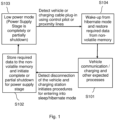
- Figure 1 shows an example flow diagram illustrating the transition between a normal mode and a lower power mode for an EVSE according to an embodiment of the present disclosure.
- EVSE is used. It should be understood that the equivalent terms of charging station or EV charging station or the like could equally be used.
- An example operation of an EVSE, in order to charge an EV, is shown in the cyclic transitions of Figure 1 , through steps S101 to S104.
- the EVSE is in a so-called 'normal mode' whereby the EVSE is connected to an EV, typically via a charging cable.
- the EVSE may be charging the EV, or be in communication with the EV.
- the EVSE detects the disconnection of the EV. The EVSE then initiates procedures for entering into a 'lower power mode'.
- 'Lower power mode' may also be referred to one of low power mode, sleep mode, or hibernate mode, in some examples.
- the EVSE stores any required data to non-volatile memory of the EVSE.
- the required data may include at least one of: a charging session start value, a charging session stop value, and meter values for the amount of energy provided.
- the required data may include locally stored variables in the EVSE to be able to wake up from hibernate mode and continue operation with the same settings/configurations.
- the EVSE may draw little to no electrical energy from the mains power source.
- the EVSE detects that an EV/EV charging cable that has connected to the EVSE. This triggers a wake-up from the 'lower power mode' and restores the data from the non-volatile memory. The EVSE can then charge the EV or communicate with the EV (i.e. back to S101).
- Power supply stages of the EVSE are powered down after the EV/EV charging cable is disconnected from the charging station.
- the 'lower power mode' will be initiated by the EVSE itself after detecting the disconnection of the EV or the EV charging cable.
- the 'lower power mode' is known as a 'hibernate mode', or a 'sleep mode.
- the disconnection may be detected using communication signals or proximity detection signals which occur between the EVSE and the EV, or between the EVSE and the EV charging cable. According to standard IEC 61851-1 these signals are referred to as control pilot signals and proximity pilot signals, respectively. In other examples and standards, these signals may be referred to using different names.
- the control pilot is a communication line used to signal charging level between the car and the EVSE.
- the control pilot can be manipulated by the EV to initiate charging as well as other information.
- the typical signal used is a 1 kHz square wave at ⁇ 12 volts generated by the EVSE to detect the presence of the vehicle, communicate the maximum allowable charging current, and control charging begin/end.
- the proximity pilot signal is used to detect the maximum allowable charging current for the charging cable used in between the EVSE and the EV.
- the proximity pilot may also provide a signal to the EVs control system so it can prevent movement while connected to the to the cable itself or to the EVSE.
- the proximity pilot signal may also be used to signal the latch release button of the charging cable to the EV.
- a charging station controller of the EVSE After the detection of the disconnection and following the completion of any pre-programmed procedures, a charging station controller of the EVSE will power down its own power supply by providing a feedback signal to the power supply stage of the charging station.
- pre-programmed procedures include sending transaction stop messages to a central management system if it is connected to a central system, or completing its local procedures for storing any needed information for any upcoming wake-up. In this period, the charging station will be in the 'lower power mode' while any parameters are stored in the non-volatile memory of the charging station.
- the power supply stages of the EVSE may be in full, or partial, power down in order to decrease power consumption to a very low level, or even to a zero watt level (as defined by the International Electrotechnical Commission, IEC). This may be performed by means of the provision of appropriate sleep mode feedback (FB), an enable signal (EN), or any other signal for the controller to ensure the EVSE remains in the 'lower power mode'.
- FB sleep mode feedback
- EN enable signal
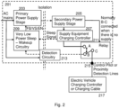
- FIG. 2 shows schematically a first example of circuitry for an EVSE 201 according to an embodiment of the present disclosure.
- Figure 2 shows the communication circuitry for the EVSE (energy transfer circuitry to charge the EV is not shown).
- the EVSE 201 comprises a primary power supply circuit 203.
- the primary power supply circuit 203 is connectable to a main power source.
- the mains power source is an alternating (AC) mains electricity source, provided by a national grid or the like.
- the main power source may be a direct (DC) source, or other suitable power source.
- the primary power supply circuit 203 of the EVSE 201 will receive electrical energy from the mains power source.
- the EVSE 201 also comprises a secondary power supply circuit 205.
- the primary power supply circuit 203 and the secondary power supply circuit 205 together may form a transformer.
- the primary power supply circuit 203 is able to induce current in the secondary power supply circuit 205.
- the secondary power supply circuit 205 is galvanically isolated from the mains power source. In this way, the functional sections of primary power supply circuit 203 and the secondary power supply circuit 205 are isolated to prevent current flow between the two circuits, with no permitted direct conduction path.
- SELV safety extra-low voltage
- PELV protected extra-low voltage
- SELV is an extra low voltage electrical circuit that is electrically separated from other circuits that carry higher voltages, isolated from the earth and from the protective earth conductors of other circuits.
- the voltage should not exceed the extra low voltage under the normal conditions or under single-fault conditions such as those from earth faults in other circuits.
- the SELV systems are separated from the earth such that a single fault cannot cause an electrical shock to anyone in contact with the system.
- IEC 61140 defines a PELV system as an electrical system in which the voltage cannot exceed extra-low voltage under normal conditions, and under single-fault conditions, except earth faults in other circuits.
- a PELV circuit only requires protective-separation from all circuits other than SELV and PELV (i.e., all circuits that might carry higher voltages), but it may have connections to other PELV systems and earth. In contrast to a SELV circuit, a PELV circuit can have a protective earth (ground) connection.
- the arrangement of the primary power supply circuit 203 and the secondary power supply circuit 205 allow for SELV and/or PELV in the secondary power supply circuit 205, in some examples.
- the secondary power supply circuit 205 is connected to a controller 207.
- the controller may be referred to as a charging controller or supply equipment charging controller (SECC), in some examples. These terms can be used interchangeably.
- SECC supply equipment charging controller
- the EVSE 201 of this example also comprises a relay 211.
- the relay 211 is connected to a contact 215.
- the contact 215 may be part of a socket to receive a charging cable of an EV, in some examples.
- the contact may be part of a plug of the EVSE that can be plugged into an EV, in some examples.
- the relay 211 is also connected to the controller 207.
- the relay 211 is also connected to a detection circuit 213.
- the relay 211 is arranged such that it can switch the connection between i) the contact 215 and the controller 207, and ii) the contact 215 and the detection circuit 213. This operation will be discussed in more detail below.
- the relay 211 switches the signal line (connection) from the EV/charging cable of the EV between the detection circuit 213 and the secondary power supply circuit 205 according to the state of the power supply (i.e., whether electrical energy is being drawn by the EVSE 201).
- the signal line is connected to the detection circuit 213 when the primary power supply circuit 203 is in sleep mode.
- the signal line is connected to the secondary power supply circuit 205 when the primary power supply circuit 203 is drawing electrical energy and the EVSE 201 is in normal (charging) operation mode.
- the controller 207 is configured to provide a sleep signal to the primary power supply circuit 203 when an EV or an EV charging cable 217 is disconnected from the EVSE 201.
- the sleep signal may be provided to the primary power supply circuit 203 via separate sleep-wakeup circuitry 209.
- the sleep-wakeup circuitry 209 provides the sleep signal to the primary power supply circuit 203.
- the sleep signal causes the primary power supply circuit to at least partially power down. In some examples, the primary power supply circuit 203 will power down completely (i.e., no electrical energy is drawn from the mains source).
- the controller 207 cannot detect a connection of an EV/charging cable of an EV 217 using control pilot or proximity pilot signals as in conventional EVSEs. This is because there is no voltage transfer/current transfer from an EV to the EVSE in many of the charging interface standards in such a situation.
- the provision of the detection circuitry 213 in the present example means that the EV/charging cable of the EV 217 can be detected when the power supply circuits are powered down.
- the detection circuit 213 is connected to the mains power source. When connected to the mains power source, and receiving electrical energy, the detection circuit 213 will consume very low energy, when compared to the primary power supply circuit 203.
- the AC mains source or a rectified form of this AC source, is used to power the detection circuitry 213.
- the detection circuitry 213 comprises a resistor. In some examples, the resistor is a high-value safety approved series resistor.
- the detection circuit 213 detects the presence of the resistor of the EV or EV charging cable 217, the detection circuit 213 knows that an EV 217 is connected to the EVSE 201.
- the detection circuit 213 then provides a wake-up signal to the primary power supply circuit 203.
- the detection circuit may provide the wake-up signal to the primary power supply circuit 203 via the sleep-wakeup circuitry 209, in some examples.
- the primary power supply circuit 203 receives the wake-up signal, the primary power supply circuit 203 will draw electrical energy from the mains source, which is used to charge the connected EV 217.
- the detection circuitry 213 is configured to detect a passive resistor in an EV charging cable 217 on a proximity pilot signal line. This resistor of the proximity pilot signal line is shown in more detail in the schematic circuit diagram of Figure 3a , discussed further below.
- the detection circuitry 213 is configured to detect a passive resistor in an EV 217 on a control pilot signal line. This resistor of the proximity pilot signal line is shown in more detail in the schematic circuit diagram of Figure 3b , discussed further below.
- a proximity pilot passive resistor or a passive resistor over the control pilot line of the charging cable or EV as the case may be forms a voltage divider type circuit with the detection circuit 213, in some examples.
- the output from the voltage divider circuit may form the wake-up signal.
- the value of the resistor may be 1 or more mega ohms, in some examples.
- the detection circuit 213 comprises any appropriate type of circuitry that can output a wake-up signal when detecting the resistor(s) of the charging cable or EV as the case may be.
- the relay 211 is used with the detection circuitry 213 because in some cases the Thevenin Equivalent resistance of the non-powered secondary circuit including the secondary power supply circuit 205 and controller 207 may be very low compared to the high value safety approved resistors in the detection circuitry 213. In some cases, this may lead to a sub-optimal performance of the detection circuit 213 as the resistance from the passive resistance on the proximity pilot line or the resistance on the EV over control pilot line may be close to the Thevenin equivalent of the secondary circuit if compared to the high value safety approved resistors of detection circuitry 213.
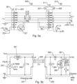
- Figure 3a shows schematically a detailed view of an example of circuitry for an EV and EV charging cable, which may be connected to the EVSE 201.
- the circuitry of Figure 3a has five main parts including an EVSE socket 301 for receiving a charging cable plug, a charging cable plug 303, a cable assembly 305, a vehicle connector 307, and a vehicle inlet 309.
- the vehicle connector 307 and the vehicle inlet 309 together form a vehicle coupler 311.
- the vehicle circuitry 315 has a connection 317 for an AC supply and a chassis connection 319.
- the first line (top line) is a proximity pilot line.
- the second line is a control pilot line.
- the third line is power live line.
- the fourth line is power neutral line.
- the fifth line is a protective earth line.
- the passive resistance of the charging cable is illustrated with the resistor (Rc) 321.
- the resistor 321 is on the proximity pilot line of the charging cable.
- the resistor 321 uses protective earth as the reference ground.
- This resistor 321 is conventionally provided as a proximity pilot resistor in EV charging cables.
- the resistor 321 is connected to the EVSE through the EVSE socket 301.
- the detection circuit 213 of the EVSE 201 is configured to detect the resistor 321 in some examples.
- Figure 3b shows schematically a detailed view of an example of circuitry for a charging side and EV side, which may be connected to the EVSE 201.
- the circuitry of Figure 3b shows a control pilot circuit between an EVSE (charging) section 351, and an EV section 353.
- the EVSE section 351 and the EV section 353 are connected with a charging cable 355.
- the EVSE section 351 comprises a signal generator 357.
- the signal used is a 1 kHz square wave at ⁇ 12 volts generated by the EVSE 201.
- a first capacitor 359 is in parallel with the signal generator 357, with a first resistor 361 in series between them.
- the EVSE section 351 is connected to protective earth.
- the EV section 353 comprises a second capacitor 363 in parallel with a second resistor 365 and a third resistor 367. There is provided a diode 369 in series between the second capacitor 363 and the second resistor 365.
- the EV section 353 is connected to earth via the chassis of the EV.
- the second resistor 365 is circled as it is this resistor that the detection circuit 213 of the EVSE 201 can detect, as described in detail above.
- the second resistor 365 uses protective earth as the reference ground.
- the second 365 and third resistors 367 are replaced with a single equivalent resistor.
- the equivalent resistor may be detected by the detection circuit 213.
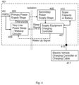
- FIG 4 shows schematically a second example of circuitry for an EVSE 401 according to an embodiment of the present disclosure.
- the operation of the EVSE 401 is similar to the operation of the EVSE 201 from Figure 2 .
- the EVSE 401 of Figure 4 differs in that a detection circuit is provided as part of the secondary circuit, the secondary circuit comprising a secondary power supply circuit and a controller.
- the detection circuit is powered by a capacitor or battery or other local store of electrical energy in this example. This will be described in more detail below.
- the EVSE 401 comprises a primary power supply circuit 403.
- the primary power supply circuit 403 is connectable to a mains power source.
- the mains power source is an alternating (AC) source, provided by a national grid or the like.
- the main power source may be a direct (DC) source, or other suitable power source.
- the primary power supply circuit 403 of the EVSE 201 will receive electrical energy from the mains power source.
- the EVSE 401 also comprises a secondary power supply circuit 405.
- the primary power supply circuit 403 and the secondary power supply circuit 405 together may form a transformer.
- the primary power supply circuit 403 is able to induce current in the secondary power supply circuit 405.
- the secondary power supply circuit 405 is galvanically isolated from the mains power source.
- the functional sections of primary power supply circuit 403 and the secondary power supply circuit 405 are isolated to prevent current flow between the two circuits, with no permitted direct conduction path.
- the arrangement of the primary power supply circuit 403 and the secondary power supply circuit 405 allow for SELV and/or PELV in the secondary power supply circuit 405, in some examples.
- the secondary power supply circuit 405 is connected to a controller 407.
- the controller may be referred to as a charging controller or supply equipment charging controller in some examples.
- the secondary power supply circuit 405 and the controller 407 form a secondary circuit.
- the secondary power supply circuit 405 is connected to a contact 415.
- the contact 415 may be a socket to receive a charging cable of an EV, in some examples.
- the contact 415 may be a plug of the EVSE 401 that can be plugged into an EV, in some examples.
- the controller 407 is configured to provide a sleep signal to the primary power supply circuit 403 when an EV or an EV charging cable 417 is disconnected from the EVSE 401.
- the sleep signal may be provided to the primary power supply circuit 403 via separate sleep-wakeup circuitry 409.
- the sleep-wakeup circuitry 409 provides the sleep signal to the primary power supply circuit 403.
- the sleep signal causes the primary power supply circuit 403 to at least partially power down. In some examples, the primary power supply circuit 403 will power down completely (i.e., no electrical energy is drawn from the mains source).
- the controller 407 cannot detect a connection of an EV/charging cable of an EV 417 using control pilot or proximity pilot signals as in conventional EVSEs. This is because there is no voltage transfer/current transfer from an EV to the EVSE in many of the charging interface standards in such a situation.
- the secondary circuit comprises a detection circuit (or detection mechanism) (not shown in Figure 4 ).
- the detection circuit is configured to detect the presence of an EV/charging cable of the EV 417, when the power supply circuits are powered down.
- the detection circuit is powered by a capacitor or battery or other local store of electrical energy 413.
- the capacitor is a super-capacitor.
- the capacitor or battery 413 or other local store of electrical energy is configured to be charged during normal mode and supply power to the detection circuit during sleep mode.
- the detection circuit when connected to the contact 415, is arranged to detect a resistor of an EV or EV charging cable 417. When the detection circuit detects the presence of the resistor, the detection circuit identifies that an EV 417 is connected to the EVSE 401. The secondary circuit then provides a wake-up signal to the primary power supply circuit 403. In some examples, the controller 407 of the secondary circuit provides the wake-up signal to the primary power supply circuit 403. The detection circuit may provide the wake-up signal to the primary power supply circuit 403 via the sleep-wakeup circuitry 409, in some examples. When the primary power supply circuit 403 receives the wake-up signal, the primary power supply circuit 403 will draw electrical energy from the mains source, which is used to charge the connected EV 417.
- the detection circuitry is configured to detect a passive resistor in an EV charging cable 417 on a proximity pilot signal line. In some examples, the detection circuitry is configured to detect a passive resistor in an EV 417 on a control pilot signal line. Examples of this are described in more detail above and the description thereof is not repeated here.
- FIG. 5 shows schematically a third example of circuitry for an EVSE 501 according to an embodiment of the present disclosure.
- the operation of the EVSE 501 is similar to the operation of the EVSE 201 of Figure 2 , and the EVSE 401 of Figure 4 .
- the EVSE 501 of Figure 5 differs from the EVSE 401 of Figure 4 in that the detection circuit/mechanism of the secondary circuit is powered by a separate low-power circuit connected to a mains source, rather than a battery/capacitor. This will be described in more detail below.
- the EVSE 501 comprises a primary power supply circuit 503.
- the primary power supply circuit 503 is connectable to a mains power source.
- the mains power source is an alternating (AC) source, provided by a national grid or the like.
- the main power source may be a direct (DC) source, or other suitable power source.
- the primary power supply circuit 503 of the EVSE 501 will receive electrical energy from the mains power source.
- the EVSE 501 also comprises a secondary power supply circuit 505.
- the primary power supply circuit 503 and the secondary power supply circuit 505 together may form a transformer.
- the primary power supply circuit 503 is able to induce current in the secondary power supply circuit 505.
- the secondary power supply circuit 505 is galvanically isolated from the mains power source.
- the functional sections of primary power supply circuit 503 and the secondary power supply circuit 505 are isolated to prevent current flow between the two circuits, with no permitted direct conduction path.
- the arrangement of the primary power supply circuit 503 and the secondary power supply circuit 505 allow for SELV and/or PELV in the secondary power supply circuit 505, in some examples.
- the secondary power supply circuit 505 is connected to a controller 507.
- the controller 507 may be referred to as a charging controller or supply equipment charging controller, in some examples.
- the secondary power supply circuit 505 and the controller 507 form a secondary circuit.
- the secondary power supply circuit 505 is connected to a contact 515.
- the contact 515 may be part of a socket to receive a charging cable of an EV, in some examples.
- the contact 515 may be part of a plug of the EVSE 501 that can be plugged into an EV, in some examples.
- the controller 507 is configured to provide a sleep signal to the primary power supply circuit when an EV or an EV charging cable 517 is disconnected from the EVSE 501.
- the sleep signal may be provided to the primary power supply circuit 503 via separate sleep-wakeup circuitry 509.
- the sleep-wakeup circuitry 509 provides the sleep signal to the primary power supply circuit 503.
- the sleep signal causes the primary power supply circuit 503 to at least partially power down. In some examples, the primary power supply circuit 503 will power down completely (i.e., no electrical energy is drawn from the mains source).
- the controller 507 cannot detect a connection of an EV/charging cable of an EV 517 using control pilot or proximity pilot signals as in conventional EVSEs. This is because there is no voltage transfer/current transfer from an EV to the EVSE in many of the charging interface standards in such a situation.
- the secondary circuit comprises a detection circuit (or detection mechanism) (not shown in Figure 5 ).
- the detection circuit is configured to detect the presence of an EV/charging cable of the EV 517, when the power supply circuits are powered down.
- the detection circuit is powered by a low-power supply circuit 513.
- the low-power supply circuit 513 is connectable to the mains power source.
- the low-power supply circuit 513 may comprise circuitry such that the low-power supply circuit 513 consumes a small amount of electrical energy from the mains power source.
- the amount of electrical energy consumed by the low-power supply circuit 513 is low compared to the consumption of electrical energy used by the primary power supply circuit 503.
- the primary power supply circuit 503 may use several watts of power while the low-power supply circuit 513 may use only a few microwatts or milliwatts. It should be understood that this is an example only, in other examples, the circuits will use different amounts of power.
- the detection circuit when connected to the contact 515, is arranged to detect a resistor of an EV or EV charging cable 517. When the detection circuit detects the presence of the resistor, the detection circuit identifies that an EV 517 is connected to the EVSE 501. The secondary circuit then provides a wake-up signal to the primary power supply circuit 503. In some examples, the controller 507 of the secondary circuit provides the wake-up signal to the primary power supply circuit 503. The detection circuit may provide the wake-up signal to the primary power supply circuit 503 via the sleep-wakeup circuitry 509, in some examples. When the primary power supply circuit 503 receives the wake-up signal, the primary power supply circuit 503 will draw electrical energy from the mains source, which is used to charge the connected EV 517.
- the detection circuitry is configured to detect a passive resistor in an EV charging cable 517 on a proximity pilot signal line. In some examples, the detection circuitry is configured to detect a passive resistor in an EV 517 on a control pilot signal line. Examples of this are described in more detail above and the description thereof is not repeated here.
- control pilot signals sent along the control pilot signal lines by the EVSE allows the EVSE to know when an EV or EV charging cable is connected to the EVSE.
- these control pilot signals, sent by the EVSE mean that the EVSE cannot fully power down, and will still consume large amounts of standby energy.
- One or more of the examples discussed above allow for a lower power usage in EVSEs in sleep mode, without the use of control pilot signals. This reduction in standby power usage seen particularly in EVSEs that are always connected to a mains power supply. Therefore, energy usage is reduced when EVSEs are in powered down/standby.
- any processor or processing system or circuitry referred to herein may in practice be provided by a single chip or integrated circuit or plural chips or integrated circuits, optionally provided as a chipset, an application-specific integrated circuit (ASIC), field-programmable gate array (FPGA), digital signal processor (DSP), graphics processing units (GPUs), etc.
- the chip or chips may comprise circuitry (as well as possibly firmware) for embodying at least one or more of a data processor or processors, a digital signal processor or processors, baseband circuitry and radio frequency circuitry, which are configurable so as to operate in accordance with the exemplary embodiments.
- the exemplary embodiments may be implemented at least in part by computer software stored in (non-transitory) memory and executable by the processor, or by hardware, or by a combination of tangibly stored software and hardware (and tangibly stored firmware).
- eMMC embedded MultiMediaCard
- flash memory or a hard disk
- non-volatile semiconductor memory including for example a solid-state drive or SSD.
Landscapes
- Engineering & Computer Science (AREA)
- Power Engineering (AREA)
- Transportation (AREA)
- Mechanical Engineering (AREA)
- Charge And Discharge Circuits For Batteries Or The Like (AREA)
Applications Claiming Priority (1)
| Application Number | Priority Date | Filing Date | Title |
|---|---|---|---|
| TR202206230 | 2022-04-19 |
Publications (1)
| Publication Number | Publication Date |
|---|---|
| EP4265468A1 true EP4265468A1 (de) | 2023-10-25 |
Family
ID=81344492
Family Applications (1)
| Application Number | Title | Priority Date | Filing Date |
|---|---|---|---|
| EP22169071.2A Withdrawn EP4265468A1 (de) | 2022-04-19 | 2022-04-20 | Verfahren und ausrüstung zum laden eines elektrischen fahrzeugs |
Country Status (1)
| Country | Link |
|---|---|
| EP (1) | EP4265468A1 (de) |
Cited By (3)
| Publication number | Priority date | Publication date | Assignee | Title |
|---|---|---|---|---|
| TWI883855B (zh) * | 2024-03-11 | 2025-05-11 | 台達電子工業股份有限公司 | 適用於電動車充電設備的控制電路及方法 |
| WO2025263716A1 (ko) * | 2024-06-17 | 2025-12-26 | 비젼디지텍(주) | 전기자동차용 충방전 v2l 모듈 |
| WO2026017819A1 (fr) * | 2024-07-18 | 2026-01-22 | Ampere Sas | Borne de recharge économe en énergie |
Citations (5)
| Publication number | Priority date | Publication date | Assignee | Title |
|---|---|---|---|---|
| US20150088354A1 (en) * | 2013-09-20 | 2015-03-26 | Denso Corporation | Electric power supply controller for vehicle |
| WO2018097640A1 (ko) * | 2016-11-25 | 2018-05-31 | 르노삼성자동차 주식회사 | 전기자동차를 충전하지 않을 때 대기전력을 차단하는 전기자동차 충전장치 및 충전방법 |
| FR3059276A1 (fr) * | 2016-11-29 | 2018-06-01 | Renault S.A.S | Dispositif combine de charge d'une batterie et d'alimentation electrique d'une machine electrique |
| DE102018219408A1 (de) * | 2018-11-14 | 2020-05-14 | Robert Bosch Gmbh | Vorrichtung und Verfahren zum Erzeugen eines Wecksignals und Ladeschnittstelle |
| CN213753998U (zh) * | 2020-10-26 | 2021-07-20 | 阳光电源股份有限公司 | 一种充电桩的供电电路、充电装置及充电桩 |
-
2022
- 2022-04-20 EP EP22169071.2A patent/EP4265468A1/de not_active Withdrawn
Patent Citations (6)
| Publication number | Priority date | Publication date | Assignee | Title |
|---|---|---|---|---|
| US20150088354A1 (en) * | 2013-09-20 | 2015-03-26 | Denso Corporation | Electric power supply controller for vehicle |
| WO2018097640A1 (ko) * | 2016-11-25 | 2018-05-31 | 르노삼성자동차 주식회사 | 전기자동차를 충전하지 않을 때 대기전력을 차단하는 전기자동차 충전장치 및 충전방법 |
| FR3059276A1 (fr) * | 2016-11-29 | 2018-06-01 | Renault S.A.S | Dispositif combine de charge d'une batterie et d'alimentation electrique d'une machine electrique |
| DE102018219408A1 (de) * | 2018-11-14 | 2020-05-14 | Robert Bosch Gmbh | Vorrichtung und Verfahren zum Erzeugen eines Wecksignals und Ladeschnittstelle |
| CN213753998U (zh) * | 2020-10-26 | 2021-07-20 | 阳光电源股份有限公司 | 一种充电桩的供电电路、充电装置及充电桩 |
| US20220131396A1 (en) * | 2020-10-26 | 2022-04-28 | Sungrow Power Supply Co., Ltd. | Power-supply circuit for charging station |
Cited By (4)
| Publication number | Priority date | Publication date | Assignee | Title |
|---|---|---|---|---|
| TWI883855B (zh) * | 2024-03-11 | 2025-05-11 | 台達電子工業股份有限公司 | 適用於電動車充電設備的控制電路及方法 |
| WO2025263716A1 (ko) * | 2024-06-17 | 2025-12-26 | 비젼디지텍(주) | 전기자동차용 충방전 v2l 모듈 |
| WO2026017819A1 (fr) * | 2024-07-18 | 2026-01-22 | Ampere Sas | Borne de recharge économe en énergie |
| FR3164663A1 (fr) * | 2024-07-18 | 2026-01-23 | Ampere Sas | Borne de recharge économe en énergie |
Similar Documents
| Publication | Publication Date | Title |
|---|---|---|
| EP4265468A1 (de) | Verfahren und ausrüstung zum laden eines elektrischen fahrzeugs | |
| CN105591460B (zh) | 用于电池管理的系统和方法 | |
| US20080247203A1 (en) | Energy Efficient Power Converter | |
| US9214807B2 (en) | Systems and methods for delivering power in response to a connection event | |
| CN105764738B (zh) | 充放电系统以及在其内使用的车辆 | |
| US20110095728A1 (en) | Method and apparatus for recharging batteries in a more efficient manner | |
| US9450452B2 (en) | Transformer coupled current capping power supply topology | |
| US8242752B2 (en) | Method and arrangement for controlling an electrical device | |
| US8958220B2 (en) | Power-saving voltage converter operation | |
| CN104685759B (zh) | 用于使用电源适配器的电子产品的待机电源切断设备 | |
| EP3506457B1 (de) | Ladesystem mit niedrigem standby-energieverbrauch und verfahren zur steuerung eines solchen systems | |
| EP4272996A1 (de) | Ladesteuerung für elektrofahrzeug | |
| CN116526531A (zh) | 一种储能装置及储能装置的控制方法 | |
| US20240294089A1 (en) | Electric vehicle charging controller | |
| CN213484578U (zh) | 掉电保护装置 | |
| TR2022006230A2 (tr) | Bi̇r elektri̇kli̇ aracin şarj edi̇lmesi̇ne yöneli̇k yöntem ve eki̇pman | |
| CN209313526U (zh) | 小配比、多功能输出的混合式ups电源车 | |
| CN222721130U (zh) | 接口断电控制装置和逆变设备 | |
| CN220874236U (zh) | 储能电源及储能系统 | |
| CN218733397U (zh) | 一种海底数据中心不间断供电系统 | |
| CN112952971B (zh) | 一种充电器系统架构 | |
| CN221828614U (zh) | 一种高压直流供电系统 | |
| CN222321186U (zh) | 放电系统及储能设备 | |
| EP4674673A1 (de) | Aufweckschaltung eines elektrofahrzeugladegeräts und verfahren zum betrieb davon | |
| EP4635785A1 (de) | Lade- und entladevorrichtung und elektrofahrzeugladegerät |
Legal Events
| Date | Code | Title | Description |
|---|---|---|---|
| STAA | Information on the status of an ep patent application or granted ep patent |
Free format text: STATUS: THE APPLICATION HAS BEEN PUBLISHED |
|
| PUAI | Public reference made under article 153(3) epc to a published international application that has entered the european phase |
Free format text: ORIGINAL CODE: 0009012 |
|
| AK | Designated contracting states |
Kind code of ref document: A1 Designated state(s): AL AT BE BG CH CY CZ DE DK EE ES FI FR GB GR HR HU IE IS IT LI LT LU LV MC MK MT NL NO PL PT RO RS SE SI SK SM TR |
|
| STAA | Information on the status of an ep patent application or granted ep patent |
Free format text: STATUS: REQUEST FOR EXAMINATION WAS MADE |
|
| 17P | Request for examination filed |
Effective date: 20240425 |
|
| RBV | Designated contracting states (corrected) |
Designated state(s): AL AT BE BG CH CY CZ DE DK EE ES FI FR GB GR HR HU IE IS IT LI LT LU LV MC MK MT NL NO PL PT RO RS SE SI SK SM TR |
|
| STAA | Information on the status of an ep patent application or granted ep patent |
Free format text: STATUS: THE APPLICATION HAS BEEN WITHDRAWN |
|
| 18W | Application withdrawn |
Effective date: 20251216 |