EP4265486A1 - Dispositif de nettoyage pour système de détection d'un véhicule à moteur - Google Patents
Dispositif de nettoyage pour système de détection d'un véhicule à moteur Download PDFInfo
- Publication number
- EP4265486A1 EP4265486A1 EP22168921.9A EP22168921A EP4265486A1 EP 4265486 A1 EP4265486 A1 EP 4265486A1 EP 22168921 A EP22168921 A EP 22168921A EP 4265486 A1 EP4265486 A1 EP 4265486A1
- Authority
- EP
- European Patent Office
- Prior art keywords
- optical surface
- cleaning device
- air
- output nozzle
- flow
- Prior art date
- Legal status (The legal status is an assumption and is not a legal conclusion. Google has not performed a legal analysis and makes no representation as to the accuracy of the status listed.)
- Withdrawn
Links
Images


Classifications
-
- B—PERFORMING OPERATIONS; TRANSPORTING
- B60—VEHICLES IN GENERAL
- B60S—SERVICING, CLEANING, REPAIRING, SUPPORTING, LIFTING, OR MANOEUVRING OF VEHICLES, NOT OTHERWISE PROVIDED FOR
- B60S1/00—Cleaning of vehicles
- B60S1/02—Cleaning windscreens, windows or optical devices
- B60S1/56—Cleaning windscreens, windows or optical devices specially adapted for cleaning other parts or devices than front windows or windscreens
Definitions
- the present invention relates to the field of the detection systems intended for a motor vehicle, in particular for their application in driving assistance devices. It relates more particularly to a device for cleaning such detection systems.
- Motor vehicles are equipped with detection systems to collect information related to the environment of the motor vehicle, in particular in order to provide the driver with assistance in the driving and/or the maneuvering of this vehicle.
- detection systems to collect information related to the environment of the motor vehicle, in particular in order to provide the driver with assistance in the driving and/or the maneuvering of this vehicle.
- cameras or other sensors such as infrared image sensors, are increasingly incorporated into modern vehicles to provide additional information to the driver.
- the detection system is commonly installed on the vehicle in such a way as to collect information on the environment in front, on the environment to the rear and on the environment to the sides of the vehicle.
- the detection system is therefore conventionally installed on the front face and/or on the rear face and/or on a rear-view mirror of the vehicle.
- the detection systems may be exposed to the fouling as from dirty water, dust or other types of sprays.
- Conventional cleaning devices are adapted to clean the detection systems to reduce or eliminate the build-up of obstructive debris on the optical surface of the detection system.
- Some techniques adapted by the conventional cleaning devices to clean the optical surfaces include ejecting a stream of fluid (water/compressed air) over the surface to be cleaned through a nozzle.
- a stream of fluid water/compressed air
- such devices are not effective in completely removing the debris, water droplets etc., as the fluid is directed above the level of debris, water droplets etc. Accordingly, it would be desirable to improve the efficiency of the cleaning devices.
- movement of the nozzle(s) may be controlled to direct the fluid at the level of debris, water droplets etc. on the optical surface.
- the movement of the nozzles may be controlled by a motor or the like.
- existing techniques may employ controllers and motor(s), for example, electronic servo motors, to control the movement of the nozzle.
- controllers and motor(s) for example, electronic servo motors, to control the movement of the nozzle.
- conventional cleaning devices may be complex and costly. It would be desirable to devise a cleaning technique without the use of the motor and other electronic controllers.
- An object of the invention is to alleviate the problems raised by the prior arts.
- an object of the invention is to provide a cleaning device, which can effectively remove substances, for instance, water droplets, deposited on an optical surface of a detection system of a motor vehicle.
- Another object of the present invention is to provide a cleaning device in which an optical surface of an optical detection system extends from an output nozzle so that the flow of air flowing out from the output nozzle is tangential to the optical surface, thereby improving the efficiency of cleaning the optical surface.
- the present invention provides a cleaning device for a detecting system of a motor vehicle, the detecting system comprising an optical surface to be cleaned.
- the cleaning device comprises a blower for generating a flow of air, and an air conveying part in communication with the blower.
- the air conveying part comprises an output nozzle to disperse the flow of air along the optical surface.
- the output nozzle is arranged such that the air flowing out from the output nozzle is tangential to the optical surface.
- the flow of air on the optical surface is at the level of water droplets and this ensures effective cleaning of the optical surface, without using additional components.
- the present invention avoids the usage of motors to control the movement of the nozzle(s) to perform the effective cleaning of the optical surface.
- the air conveying part comprises an input nozzle in connection with the blower, and a fan arranged to direct the air from the input nozzle to the output nozzle, which includes a pair of parallel walls extending from its downstream end to its upstream end.
- the output nozzle may be arranged on one of the edges of a front face of a sensor housing.
- a first end of the optical surface is disposed in the output nozzle at the upstream end and aligned with one of its walls at the upstream end to form a continuous portion with the wall.
- a portion of the optical surface is formed with the output nozzle such that the flow of air is tangential to the optical surface.
- the first end of the optical surface is of a curved shape.
- the first end of the optical surface may be slanted or curved to receive the first end of the optical surface in a slot provided on the output nozzle, thereby forming a continuous portion with the wall of the output nozzle.
- a second end opposite to the first end of the optical surface is fixed to a body of the optical detecting system.
- the first end of the optical surface is fixed with the output nozzle by one or more of: a mechanical fixation means, glue, and adhesive tape.
- This fixation of the optical surface with the output nozzle ensures to form a continuous portion with the wall of the output nozzle.
- the optical surface and the output nozzle may be formed as separate components and assembled together to form the continuous portion.
- the optical surface and the output nozzle may be formed as a single component such that the flow of air is tangential to the optical surface.
- the substance comprises one or more water droplets.
- the water droplets are either of same sizes or of different sizes.
- the air conveying part is made of plastic material.
- the output nozzle is arranged to be in contact with any one of the sides of the optical surface.
- the present invention relates to a detection system comprising at least one sensor including an optical surface to be cleaned, and a cleaning device as has just been described previously.
- the present invention is also related to a motor vehicle equipped with the detection system as has just been presented.
- upstream and downstream refer to the direction of flow of the fluids whether they are cleaning or drying fluids, in the cleaning device according to the invention.
- upstream refers to the side of the device according to the invention through which these fluids are admitted into it
- downstream refers to the side of the device according to the invention through which the fluids are dispensed out of it, in particular toward an optical surface of a detection system of a motor vehicle.
- Motor vehicles are equipped with detection systems to collect information on the environment of the motor vehicle, in particular in order to provide the driver with assistance in the driving and/or the maneuvering of this vehicle. It will be appreciated that, without departing from the scope of the invention, the motor vehicle may include a number of sensors, devices, and/or systems that are capable of assisting in driving operations.
- Examples of the various sensors and systems may include, but are in no way limited to, one or more of cameras (e.g., independent, stereo, combined image, etc.), infrared (IR) sensors, radio frequency (RF) sensors, ultrasonic sensors (e.g., transducers, transceivers, etc.), RADAR sensors (e.g., object-detection sensors and/or systems), LIDAR systems, odometry sensors and/or devices (e.g., encoders, etc.), orientation sensors (e.g., accelerometers, gyroscopes, magnetometer, etc.), navigation sensors and systems (e.g., GPS, etc.), and other ranging, imaging, and/or object-detecting sensors.
- cameras e.g., independent, stereo, combined image, etc.
- IR infrared
- RF radio frequency
- ultrasonic sensors e.g., transducers, transceivers, etc.
- RADAR sensors e.g., object-det
- the sensors may be disposed in an interior space of the vehicle and/or on an outside of the vehicle. In some embodiments, the sensors and systems may be disposed in one or more portions of a vehicle (e.g., the frame, a body panel, a compartment, etc.).
- the optical detection systems equipped to the motor vehicle may be exposed to the fouling as from dirty water, dust or other types of sprays.
- the present invention is directed to provide a cleaning device which can effectively remove substances, for instance, water droplets, deposited on an optical surface of a sensor of a detection system of a vehicle.
- Fig.1a shows a perspective view of a portion of a cleaning device for cleaning an optical surface of a detection system of a motor vehicle, according to an embodiment of the present invention.
- Fig.1b shows a side view of the portion of the cleaning device shown in Fig.1a , according to an embodiment of the present invention.
- Fig.2a shows a perspective view of an output nozzle of the cleaning device shown in Fig.1a , according to an embodiment of the present invention.
- Fig.2b shows a side view of the output nozzle of Fig.2a , according to an embodiment of the present invention.
- Fig.3a shows flow of air that is guided onto an optical surface of a sensor of a detection system, according to an embodiment of the present invention.
- Fig.3b shows a sectional view of a portion of the cleaning device shown in Fig.1a , according to an embodiment of the present invention.
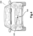
- Fig.4 shows a perspective view of an exemplary motor vehicle equipped with an optical detection system and an associated cleaning device, according to an embodiment of the present invention.
- the cleaning device for a detecting system of a motor vehicle is provided according to an embodiment of the present invention.
- the detecting system (not shown in Figures) comprises a sensor that is adapted to collect information about the vehicle's environment is accommodated within a sensor housing (not shown in Figures), and the sensor is provided with an optical surface 105.
- the sensor housing may enclose the sensor in a hermetic and sealed manner.
- the optical surface 105 is generally configured as rectangle delimited by four edges. Note that inside the planes in which the four edges extend, the edges are either rectilinear or curvilinear, in particular in an arc.
- the cleaning device 100 comprises an air conveying part having at least an input nozzle (not shown in Figures), a fan (not shown in Figures), and an output nozzle 110.
- the air conveying part is made of plastic material.
- the output nozzle 110 may be arranged on one of the edges of a front face of the sensor housing. It should be noted that only a portion of the cleaning device 100 is shown in the Fig.1a and Fig.1b for the purpose of discussion and in order better to illustrate the present invention.
- Fig.1a and Fig.1b illustrates the portion of the cleaning device 100 in which the optical surface 105 arranged in proximity to the output nozzle 110, which is adapted to direct the flow of air onto the optical surface 105 to effectively remove the substance deposited on the optical surface.
- the substance comprising one or more water droplets 115, which are either of same sizes or of different sizes.
- Fig.2a and Fig.2b illustrate the structure of output nozzle 110 of the cleaning device 100, according to the embodiment of the present invention.
- the output nozzle 110 is arranged such that the flow of air flowing out from the output nozzle 110 is tangential to the optical surface 105.
- the output nozzle 110 includes a pair of parallel walls 120a, 120b extending longitudinally from its downstream end to its upstream end. The upstream end may be arranged substantially perpendicular to the downstream end.
- the pair of parallel walls 120a, 120b may be connected by two opposite sidewalls 125a, 125b, as shown in Fig.2a and Fig.2b to define an air passage channel.
- the downstream end of the output nozzle 110 may be arranged to be in communication with the fan or the input nozzle. Additionally, the upstream end of the output nozzle 110 may be dimensioned to be curved. In other words, it is understood that, a top wall 130 of the output nozzle 110 and a first wall 120a of the pair of parallel walls 120a, 120b may be joined together in a curved manner. It is understood to a person skilled in the art that the output nozzle can be dimensioned in different ways based on the requirements and space availability.
- the output nozzle 110 may be formed with an outlet portion 135, which is positioned downwardly from the top wall 130 and aligned in line with a second wall 120b of the pair of parallel walls 120a, 120b. Further, the outlet portion 135 is an aperture through which the flow of air is directed over the optical surface 110, as shown in Fig.3b .
- the outlet portion 135 is delimited by four edges, including two longitudinal edges such as a first longitudinal edge 140a and a second longitudinal edge 140b and two lateral edges such as first lateral edge 145a and a second lateral edge 145b.
- the first lateral edge 145a and the second lateral edge 145b projects downwardly from the first longitudinal edge 140a at its longitudinal ends.
- the first longitudinal edge 140a, the first lateral edge 145a, and the second lateral edge 145b forms a U-shape, as can be seen from Fig.2a .
- a portion of the optical surface 105 is formed with the output nozzle 110 such that the flow of air on the optical surface 105 is tangential to the optical surface 105, as shown in Fig.3a and Fig.3b .
- the outlet portion 135 of the output nozzle 110 may be formed with a slot 150 to receive a first end 155 (shown in Fig. 2b ) of the optical surface 105, and a second end 160 (shown in Fig. 1b ) opposite to the first end 155 of the optical surface 105 may be fixed to a body of the detecting system.
- the slot 150 may be formed below the first and second lateral edges 145a, 145b and above the second longitudinal edge 140b, as can be seen in Fig.2a and Fig.2b .
- the first end 155 of the optical surface 105 may be disposed of in the output nozzle 110 at its upstream end and aligned with one of its walls 120a, 120b at the upstream end to form a continuous portion with the wall 120a. This is clearly seen in Fig.3b .
- the first end 155 of the optical surface 105 may be slanted or curved to accommodate the first end 155 of the optical surface 105 in the slot 150 provided on the outlet portion 135 of the output nozzle 110, thereby forming a continuous portion with the wall 120a of the output nozzle 110.
- This arrangement ensures that the air flowing out from the output nozzle 110 is tangential to the optical surface 105.
- the slot 150 and the first end 155 of the optical surface 105 can be dimensioned in such a way that the slot 150 is adapted to receive the first end 155 of the optical surface 105.
- the first end 155 of the optical surface 105 may be fixed to the slot 150 of the output nozzle 110 at least by one of: a mechanical fixation means, glue, and adhesive tape.
- This fixation of the optical surface 105 with the output nozzle 110 ensures to form a continuous portion with the wall 120a of the output nozzle 110, as can be seen in Fig.3b . Thus, it avoids any interruptions in the air flow that is directed towards the optical surface. Further, it is understood that the direction of the flow of air that exits the outlet portion 135 is substantially perpendicular to the direction of the flow of air that enters the output nozzle 110.
- the output nozzle 110 and the optical surface 105 may be formed as a single component.
- a compact cleaning device can be realised and additionally it ensures efficient shaping of the flow of air because of the continuity of the surface from the interior of the output nozzle 110 to the optical surface 105.
- the output nozzle 110 and the optical surface 105 may be formed as different components and assembled together.
- the cleaning device 100 can be more flexible in terms of configuration.
- the cleaning device 100 further comprises a blower (not shown in Figures) for generating the flow of air and the air conveying part arranged to be in communication with the blower.
- the output nozzle 110 may be arranged to receive the flow of air from the input nozzle and guided to disperse the flow of air linearly across the optical surface105 through the outlet portion 135 to remove substances deposited on the optical surface 105.
- the output nozzle 110 is arranged to disperse the flow of air parallel to the plane of the optical surface 110 as can be seen in Fig.3a . That is to say, the air flowing out from the output nozzle 110 is tangential to the optical surface 105, as can be seen from Fig.3a and Fig.3b .
- the flow of air is drawn from the supply source, for instance a blower (not shown in Figures), and guided towards the downstream end of the output nozzle 110 via the input nozzle. From the downstream end of the output nozzle, the flow of air is guided towards the outlet portion 135 in a direction 'A' as shown in the Fig.1b , and from the outlet portion 135, the flow of air is directed onto the optical surface 110 along direction 'B', which is substantially perpendicular to the direction 'A'. As previously discussed, as the portion of the optical surface 105 is formed with the output nozzle 110, the flow of air directed onto the optical surface 105 is tangential to the optical surface 105, thereby effectively removing the substance deposited on the optical surface 105.
- the supply source for instance a blower (not shown in Figures)
- the flow of air is guided towards the outlet portion 135 in a direction 'A' as shown in the Fig.1b , and from the outlet portion 135, the flow of air is directed onto the optical surface 110 along direction
- the flow of air on the optical surface 105 is at the level of water droplets 115, which ensures effective cleaning of the optical surface 105, without using additional components.
- the present invention avoids the usage of motors to control the movement of the nozzle(s) to perform the effective cleaning of the optical surface 110.
- the present invention is also related to a motor vehicle equipped with the detection system as has just been presented.
- the motor vehicle 400 is equipped with a detecting system 405 which includes the cleaning device 100 as discussed in previous embodiments.
- the detection system 405 can be provided on other faces of the vehicle.
- the detection system 405 may be provided on at least one of: a vehicle front, vehicle aft or rear, vehicle roof, at least one vehicle side, a vehicle undercarriage, and a vehicle interior.
- Fig.4 although shown in the form of a car, it should be appreciated that the vehicle described herein may include any conveyance or model of a conveyance, where the conveyance was designed for the purpose of moving one or more tangible objects, such as people, animals, cargo, and the like.
- vehicle does not require that a conveyance moves or is capable of movement.
- Typical vehicles may include but are in no way limited to cars, trucks, motorcycles, buses, automobiles, trains, railed conveyances, boats, ships, marine conveyances, submarine conveyances, airplanes, space craft, flying machines, human-powered conveyances, and the like.
Landscapes
- Engineering & Computer Science (AREA)
- Mechanical Engineering (AREA)
- Vehicle Cleaning, Maintenance, Repair, Refitting, And Outriggers (AREA)
Priority Applications (1)
| Application Number | Priority Date | Filing Date | Title |
|---|---|---|---|
| EP22168921.9A EP4265486A1 (fr) | 2022-04-20 | 2022-04-20 | Dispositif de nettoyage pour système de détection d'un véhicule à moteur |
Applications Claiming Priority (1)
| Application Number | Priority Date | Filing Date | Title |
|---|---|---|---|
| EP22168921.9A EP4265486A1 (fr) | 2022-04-20 | 2022-04-20 | Dispositif de nettoyage pour système de détection d'un véhicule à moteur |
Publications (1)
| Publication Number | Publication Date |
|---|---|
| EP4265486A1 true EP4265486A1 (fr) | 2023-10-25 |
Family
ID=81344276
Family Applications (1)
| Application Number | Title | Priority Date | Filing Date |
|---|---|---|---|
| EP22168921.9A Withdrawn EP4265486A1 (fr) | 2022-04-20 | 2022-04-20 | Dispositif de nettoyage pour système de détection d'un véhicule à moteur |
Country Status (1)
| Country | Link |
|---|---|
| EP (1) | EP4265486A1 (fr) |
Citations (4)
| Publication number | Priority date | Publication date | Assignee | Title |
|---|---|---|---|---|
| US20150138357A1 (en) * | 2011-03-10 | 2015-05-21 | Alan Scot Romack | Integrated Automotive System, Pop Up Nozzle Assembly and Remote Control Method for Cleaning a Wide Angle Image Sensors Exterior Surface |
| US20180186342A1 (en) * | 2015-06-30 | 2018-07-05 | Koito Manufacturing Co., Ltd. | Foreign matter removal device and vehicle provided with same |
| US20210179025A1 (en) * | 2019-12-16 | 2021-06-17 | PlusAI Corp | System and method for a sensor protection system |
| US20220063567A1 (en) * | 2018-12-26 | 2022-03-03 | Koito Manufacturing Co., Ltd. | Vehicle cleaner unit and vehicle cleaner system |
-
2022
- 2022-04-20 EP EP22168921.9A patent/EP4265486A1/fr not_active Withdrawn
Patent Citations (4)
| Publication number | Priority date | Publication date | Assignee | Title |
|---|---|---|---|---|
| US20150138357A1 (en) * | 2011-03-10 | 2015-05-21 | Alan Scot Romack | Integrated Automotive System, Pop Up Nozzle Assembly and Remote Control Method for Cleaning a Wide Angle Image Sensors Exterior Surface |
| US20180186342A1 (en) * | 2015-06-30 | 2018-07-05 | Koito Manufacturing Co., Ltd. | Foreign matter removal device and vehicle provided with same |
| US20220063567A1 (en) * | 2018-12-26 | 2022-03-03 | Koito Manufacturing Co., Ltd. | Vehicle cleaner unit and vehicle cleaner system |
| US20210179025A1 (en) * | 2019-12-16 | 2021-06-17 | PlusAI Corp | System and method for a sensor protection system |
Similar Documents
| Publication | Publication Date | Title |
|---|---|---|
| US11598865B2 (en) | Sensor assembly with cleaning | |
| US9409529B2 (en) | Camera system and vehicle | |
| US11478827B2 (en) | Sensor assembly with cleaning | |
| US10302744B1 (en) | Sensor assembly | |
| US11155243B2 (en) | Optical system to facilitate vehicle operation, cleaning system to clean an optical element of the optical system and hollow protective plastic enclosure for use therein | |
| US10928225B1 (en) | Vehicle sensor assembly | |
| US10604122B2 (en) | Foreign matter removal device and vehicle provided with same | |
| US10435077B2 (en) | Vehicle sensor cleaning | |
| CN107709104B (zh) | 异物除去装置以及具有该异物除去装置的车辆 | |
| CN109141494A (zh) | 传感器设备 | |
| US12172604B2 (en) | Vehicle roof comprising a support and a roof module | |
| US20220126790A1 (en) | Vehicular cleaner and vehicular cleaner unit | |
| US20210063540A1 (en) | Sensor assembly for autonomous vehicle | |
| US12539829B2 (en) | Sensor assembly with baffles | |
| CN209987893U (zh) | 车辆系统 | |
| US20240270178A1 (en) | Sensor assembly | |
| WO2022268553A1 (fr) | Dispositif de nettoyage d'une surface optique d'un véhicule automobile telle qu'une surface optique de capteur d'un système de détection | |
| EP4265486A1 (fr) | Dispositif de nettoyage pour système de détection d'un véhicule à moteur | |
| WO2022093645A1 (fr) | Procédé et système de déviation d'air dynamique vers des capteurs de véhicule | |
| US12504521B2 (en) | Sensor assembly with velocity stack | |
| US11780409B2 (en) | Sensor apparatus with cleaning | |
| CN113552553A (zh) | 带清洁功能的传感器设备 | |
| EP4266111B1 (fr) | Système de détection optique pour un véhicule à moteur | |
| US20240200989A1 (en) | Sensor assembly | |
| US20240151833A1 (en) | Sensor assembly with duct |
Legal Events
| Date | Code | Title | Description |
|---|---|---|---|
| STAA | Information on the status of an ep patent application or granted ep patent |
Free format text: STATUS: THE APPLICATION HAS BEEN PUBLISHED |
|
| PUAI | Public reference made under article 153(3) epc to a published international application that has entered the european phase |
Free format text: ORIGINAL CODE: 0009012 |
|
| AK | Designated contracting states |
Kind code of ref document: A1 Designated state(s): AL AT BE BG CH CY CZ DE DK EE ES FI FR GB GR HR HU IE IS IT LI LT LU LV MC MK MT NL NO PL PT RO RS SE SI SK SM TR |
|
| STAA | Information on the status of an ep patent application or granted ep patent |
Free format text: STATUS: THE APPLICATION IS DEEMED TO BE WITHDRAWN |
|
| 18D | Application deemed to be withdrawn |
Effective date: 20240426 |