EP4265515A1 - Machine de transport - Google Patents
Machine de transport Download PDFInfo
- Publication number
- EP4265515A1 EP4265515A1 EP22818162.4A EP22818162A EP4265515A1 EP 4265515 A1 EP4265515 A1 EP 4265515A1 EP 22818162 A EP22818162 A EP 22818162A EP 4265515 A1 EP4265515 A1 EP 4265515A1
- Authority
- EP
- European Patent Office
- Prior art keywords
- hydrogen
- nitrogen
- ammonia
- transport equipment
- tank
- Prior art date
- Legal status (The legal status is an assumption and is not a legal conclusion. Google has not performed a legal analysis and makes no representation as to the accuracy of the status listed.)
- Pending
Links
Images




Classifications
-
- B—PERFORMING OPERATIONS; TRANSPORTING
- B63—SHIPS OR OTHER WATERBORNE VESSELS; RELATED EQUIPMENT
- B63H—MARINE PROPULSION OR STEERING
- B63H21/00—Use of propulsion power plant or units on vessels
- B63H21/38—Apparatus or methods specially adapted for use on marine vessels, for handling power plant or unit liquids, e.g. lubricants, coolants, fuels or the like
-
- B—PERFORMING OPERATIONS; TRANSPORTING
- B60—VEHICLES IN GENERAL
- B60L—PROPULSION OF ELECTRICALLY-PROPELLED VEHICLES; SUPPLYING ELECTRIC POWER FOR AUXILIARY EQUIPMENT OF ELECTRICALLY-PROPELLED VEHICLES; ELECTRODYNAMIC BRAKE SYSTEMS FOR VEHICLES IN GENERAL; MAGNETIC SUSPENSION OR LEVITATION FOR VEHICLES; MONITORING OPERATING VARIABLES OF ELECTRICALLY-PROPELLED VEHICLES; ELECTRIC SAFETY DEVICES FOR ELECTRICALLY-PROPELLED VEHICLES
- B60L50/00—Electric propulsion with power supplied within the vehicle
- B60L50/50—Electric propulsion with power supplied within the vehicle using propulsion power supplied by batteries or fuel cells
- B60L50/70—Electric propulsion with power supplied within the vehicle using propulsion power supplied by batteries or fuel cells using power supplied by fuel cells
-
- B—PERFORMING OPERATIONS; TRANSPORTING
- B60—VEHICLES IN GENERAL
- B60L—PROPULSION OF ELECTRICALLY-PROPELLED VEHICLES; SUPPLYING ELECTRIC POWER FOR AUXILIARY EQUIPMENT OF ELECTRICALLY-PROPELLED VEHICLES; ELECTRODYNAMIC BRAKE SYSTEMS FOR VEHICLES IN GENERAL; MAGNETIC SUSPENSION OR LEVITATION FOR VEHICLES; MONITORING OPERATING VARIABLES OF ELECTRICALLY-PROPELLED VEHICLES; ELECTRIC SAFETY DEVICES FOR ELECTRICALLY-PROPELLED VEHICLES
- B60L50/00—Electric propulsion with power supplied within the vehicle
- B60L50/90—Electric propulsion with power supplied within the vehicle using propulsion power supplied by specific means not covered by groups B60L50/10 - B60L50/50, e.g. by direct conversion of thermal nuclear energy into electricity
-
- B—PERFORMING OPERATIONS; TRANSPORTING
- B63—SHIPS OR OTHER WATERBORNE VESSELS; RELATED EQUIPMENT
- B63B—SHIPS OR OTHER WATERBORNE VESSELS; EQUIPMENT FOR SHIPPING
- B63B25/00—Load-accommodating arrangements, e.g. stowing, trimming; Vessels characterised thereby
- B63B25/02—Load-accommodating arrangements, e.g. stowing, trimming; Vessels characterised thereby for bulk goods
- B63B25/08—Load-accommodating arrangements, e.g. stowing, trimming; Vessels characterised thereby for bulk goods fluid
-
- B—PERFORMING OPERATIONS; TRANSPORTING
- B63—SHIPS OR OTHER WATERBORNE VESSELS; RELATED EQUIPMENT
- B63H—MARINE PROPULSION OR STEERING
- B63H21/00—Use of propulsion power plant or units on vessels
- B63H21/12—Use of propulsion power plant or units on vessels the vessels being motor-driven
- B63H21/14—Use of propulsion power plant or units on vessels the vessels being motor-driven relating to internal-combustion engines
-
- B—PERFORMING OPERATIONS; TRANSPORTING
- B63—SHIPS OR OTHER WATERBORNE VESSELS; RELATED EQUIPMENT
- B63H—MARINE PROPULSION OR STEERING
- B63H21/00—Use of propulsion power plant or units on vessels
- B63H21/12—Use of propulsion power plant or units on vessels the vessels being motor-driven
- B63H21/17—Use of propulsion power plant or units on vessels the vessels being motor-driven by electric motor
-
- B—PERFORMING OPERATIONS; TRANSPORTING
- B63—SHIPS OR OTHER WATERBORNE VESSELS; RELATED EQUIPMENT
- B63J—AUXILIARIES ON VESSELS
- B63J3/00—Driving of auxiliaries
- B63J3/02—Driving of auxiliaries from propulsion power plant
-
- C—CHEMISTRY; METALLURGY
- C01—INORGANIC CHEMISTRY
- C01B—NON-METALLIC ELEMENTS; COMPOUNDS THEREOF; METALLOIDS OR COMPOUNDS THEREOF NOT COVERED BY SUBCLASS C01C
- C01B3/00—Hydrogen; Gaseous mixtures containing hydrogen; Separation of hydrogen from mixtures containing it; Purification of hydrogen; Reversible storage of hydrogen
- C01B3/02—Production of hydrogen; Production of gaseous mixtures containing hydrogen
- C01B3/04—Production of hydrogen; Production of gaseous mixtures containing hydrogen by decomposition of inorganic compounds
- C01B3/047—Decomposition of ammonia
-
- F—MECHANICAL ENGINEERING; LIGHTING; HEATING; WEAPONS; BLASTING
- F02—COMBUSTION ENGINES; HOT-GAS OR COMBUSTION-PRODUCT ENGINE PLANTS
- F02M—SUPPLYING COMBUSTION ENGINES IN GENERAL WITH COMBUSTIBLE MIXTURES OR CONSTITUENTS THEREOF
- F02M21/00—Apparatus for supplying engines with non-liquid fuels, e.g. gaseous fuels stored in liquid form
- F02M21/02—Apparatus for supplying engines with non-liquid fuels, e.g. gaseous fuels stored in liquid form for gaseous fuels
- F02M21/0203—Apparatus for supplying engines with non-liquid fuels, e.g. gaseous fuels stored in liquid form for gaseous fuels characterised by the type of gaseous fuel
- F02M21/0206—Non-hydrocarbon fuels, e.g. hydrogen, ammonia or carbon monoxide
-
- F—MECHANICAL ENGINEERING; LIGHTING; HEATING; WEAPONS; BLASTING
- F02—COMBUSTION ENGINES; HOT-GAS OR COMBUSTION-PRODUCT ENGINE PLANTS
- F02M—SUPPLYING COMBUSTION ENGINES IN GENERAL WITH COMBUSTIBLE MIXTURES OR CONSTITUENTS THEREOF
- F02M21/00—Apparatus for supplying engines with non-liquid fuels, e.g. gaseous fuels stored in liquid form
- F02M21/02—Apparatus for supplying engines with non-liquid fuels, e.g. gaseous fuels stored in liquid form for gaseous fuels
- F02M21/0218—Details on the gaseous fuel supply system, e.g. tanks, valves, pipes, pumps, rails, injectors or mixers
- F02M21/0227—Means to treat or clean gaseous fuels or fuel systems, e.g. removal of tar, cracking, reforming or enriching
-
- H—ELECTRICITY
- H01—ELECTRIC ELEMENTS
- H01M—PROCESSES OR MEANS, e.g. BATTERIES, FOR THE DIRECT CONVERSION OF CHEMICAL ENERGY INTO ELECTRICAL ENERGY
- H01M8/00—Fuel cells; Manufacture thereof
- H01M8/04—Auxiliary arrangements, e.g. for control of pressure or for circulation of fluids
- H01M8/04223—Auxiliary arrangements, e.g. for control of pressure or for circulation of fluids during start-up or shut-down; Depolarisation or activation, e.g. purging; Means for short-circuiting defective fuel cells
- H01M8/04231—Purging of the reactants
-
- B—PERFORMING OPERATIONS; TRANSPORTING
- B63—SHIPS OR OTHER WATERBORNE VESSELS; RELATED EQUIPMENT
- B63B—SHIPS OR OTHER WATERBORNE VESSELS; EQUIPMENT FOR SHIPPING
- B63B17/00—Vessels parts, details, or accessories, not otherwise provided for
- B63B17/0027—Tanks for fuel or the like ; Accessories therefor, e.g. tank filler caps
-
- B—PERFORMING OPERATIONS; TRANSPORTING
- B63—SHIPS OR OTHER WATERBORNE VESSELS; RELATED EQUIPMENT
- B63H—MARINE PROPULSION OR STEERING
- B63H21/00—Use of propulsion power plant or units on vessels
- B63H2021/003—Use of propulsion power plant or units on vessels the power plant using fuel cells for energy supply or accumulation, e.g. for buffering photovoltaic energy
-
- B—PERFORMING OPERATIONS; TRANSPORTING
- B63—SHIPS OR OTHER WATERBORNE VESSELS; RELATED EQUIPMENT
- B63J—AUXILIARIES ON VESSELS
- B63J3/00—Driving of auxiliaries
-
- C—CHEMISTRY; METALLURGY
- C01—INORGANIC CHEMISTRY
- C01B—NON-METALLIC ELEMENTS; COMPOUNDS THEREOF; METALLOIDS OR COMPOUNDS THEREOF NOT COVERED BY SUBCLASS C01C
- C01B2203/00—Integrated processes for the production of hydrogen or synthesis gas
- C01B2203/02—Processes for making hydrogen or synthesis gas
- C01B2203/0266—Processes for making hydrogen or synthesis gas containing a decomposition step
- C01B2203/0277—Processes for making hydrogen or synthesis gas containing a decomposition step containing a catalytic decomposition step
-
- C—CHEMISTRY; METALLURGY
- C01—INORGANIC CHEMISTRY
- C01B—NON-METALLIC ELEMENTS; COMPOUNDS THEREOF; METALLOIDS OR COMPOUNDS THEREOF NOT COVERED BY SUBCLASS C01C
- C01B2203/00—Integrated processes for the production of hydrogen or synthesis gas
- C01B2203/04—Integrated processes for the production of hydrogen or synthesis gas containing a purification step for the hydrogen or the synthesis gas
- C01B2203/0405—Purification by membrane separation
-
- C—CHEMISTRY; METALLURGY
- C01—INORGANIC CHEMISTRY
- C01B—NON-METALLIC ELEMENTS; COMPOUNDS THEREOF; METALLOIDS OR COMPOUNDS THEREOF NOT COVERED BY SUBCLASS C01C
- C01B2203/00—Integrated processes for the production of hydrogen or synthesis gas
- C01B2203/04—Integrated processes for the production of hydrogen or synthesis gas containing a purification step for the hydrogen or the synthesis gas
- C01B2203/042—Purification by adsorption on solids
- C01B2203/043—Regenerative adsorption process in two or more beds, one for adsorption, the other for regeneration
-
- C—CHEMISTRY; METALLURGY
- C01—INORGANIC CHEMISTRY
- C01B—NON-METALLIC ELEMENTS; COMPOUNDS THEREOF; METALLOIDS OR COMPOUNDS THEREOF NOT COVERED BY SUBCLASS C01C
- C01B2203/00—Integrated processes for the production of hydrogen or synthesis gas
- C01B2203/06—Integration with other chemical processes
- C01B2203/066—Integration with other chemical processes with fuel cells
-
- C—CHEMISTRY; METALLURGY
- C01—INORGANIC CHEMISTRY
- C01B—NON-METALLIC ELEMENTS; COMPOUNDS THEREOF; METALLOIDS OR COMPOUNDS THEREOF NOT COVERED BY SUBCLASS C01C
- C01B2203/00—Integrated processes for the production of hydrogen or synthesis gas
- C01B2203/14—Details of the flowsheet
- C01B2203/146—At least two purification steps in series
-
- C—CHEMISTRY; METALLURGY
- C01—INORGANIC CHEMISTRY
- C01B—NON-METALLIC ELEMENTS; COMPOUNDS THEREOF; METALLOIDS OR COMPOUNDS THEREOF NOT COVERED BY SUBCLASS C01C
- C01B2203/00—Integrated processes for the production of hydrogen or synthesis gas
- C01B2203/80—Aspect of integrated processes for the production of hydrogen or synthesis gas not covered by groups C01B2203/02 - C01B2203/1695
- C01B2203/84—Energy production
-
- F—MECHANICAL ENGINEERING; LIGHTING; HEATING; WEAPONS; BLASTING
- F02—COMBUSTION ENGINES; HOT-GAS OR COMBUSTION-PRODUCT ENGINE PLANTS
- F02M—SUPPLYING COMBUSTION ENGINES IN GENERAL WITH COMBUSTIBLE MIXTURES OR CONSTITUENTS THEREOF
- F02M25/00—Engine-pertinent apparatus for adding non-fuel substances or small quantities of secondary fuel to combustion-air, main fuel or fuel-air mixture
-
- H—ELECTRICITY
- H01—ELECTRIC ELEMENTS
- H01M—PROCESSES OR MEANS, e.g. BATTERIES, FOR THE DIRECT CONVERSION OF CHEMICAL ENERGY INTO ELECTRICAL ENERGY
- H01M2250/00—Fuel cells for particular applications; Specific features of fuel cell system
- H01M2250/20—Fuel cells in motive systems, e.g. vehicle, ship, plane
-
- H—ELECTRICITY
- H01—ELECTRIC ELEMENTS
- H01M—PROCESSES OR MEANS, e.g. BATTERIES, FOR THE DIRECT CONVERSION OF CHEMICAL ENERGY INTO ELECTRICAL ENERGY
- H01M8/00—Fuel cells; Manufacture thereof
- H01M8/04—Auxiliary arrangements, e.g. for control of pressure or for circulation of fluids
- H01M8/04082—Arrangements for control of reactant parameters, e.g. pressure or concentration
- H01M8/04201—Reactant storage and supply, e.g. means for feeding, pipes
-
- H—ELECTRICITY
- H01—ELECTRIC ELEMENTS
- H01M—PROCESSES OR MEANS, e.g. BATTERIES, FOR THE DIRECT CONVERSION OF CHEMICAL ENERGY INTO ELECTRICAL ENERGY
- H01M8/00—Fuel cells; Manufacture thereof
- H01M8/06—Combination of fuel cells with means for production of reactants or for treatment of residues
- H01M8/0606—Combination of fuel cells with means for production of reactants or for treatment of residues with means for production of gaseous reactants
-
- Y—GENERAL TAGGING OF NEW TECHNOLOGICAL DEVELOPMENTS; GENERAL TAGGING OF CROSS-SECTIONAL TECHNOLOGIES SPANNING OVER SEVERAL SECTIONS OF THE IPC; TECHNICAL SUBJECTS COVERED BY FORMER USPC CROSS-REFERENCE ART COLLECTIONS [XRACs] AND DIGESTS
- Y02—TECHNOLOGIES OR APPLICATIONS FOR MITIGATION OR ADAPTATION AGAINST CLIMATE CHANGE
- Y02T—CLIMATE CHANGE MITIGATION TECHNOLOGIES RELATED TO TRANSPORTATION
- Y02T70/00—Maritime or waterways transport
- Y02T70/50—Measures to reduce greenhouse gas emissions related to the propulsion system
Definitions
- the present invention relates to transport equipment that uses, as fuel, hydrogen produced by reforming ammonia.
- GHG greenhouse gas
- IMO International Maritime Organization
- Patent Literature 1 there is a disclosure of a vessel loaded with ammonia as a combustible gas, in which an internal combustion engine is activated with the ammonia.
- Patent Literature 1 In combustion of ammonia by the internal combustion engine as disclosed in Patent Literature 1, dinitrogen oxide (N 2 O), which has a greenhouse effect about 300 times that of carbon dioxide, is produced, and hence GHG zero emission is not achieved.
- an inert gas supply device is required in order to supply an inert gas, and, for example, it is required to mount a large facility such as a nitrogen gas production device.
- An object of the present invention is to provide transport equipment that uses, as fuel, hydrogen produced by reforming ammonia.
- transport equipment including: a first container configured to store ammonia; and a hydrogen production device configured to produce hydrogen and nitrogen by reforming the ammonia, wherein the hydrogen is used as fuel.
- the transport equipment that uses, as fuel, hydrogen produced by reforming ammonia can be provided.
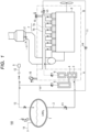
- FIG. 1 is a schematic view for illustrating the transport equipment 100 having a power generation system in this embodiment mounted thereon.
- the power generation system in this embodiment includes an ammonia tank 1 (first container) that stores ammonia serving as an energy source, a hydrogen production device A that produces hydrogen and nitrogen by reforming ammonia, and an internal combustion engine 8 that uses, as fuel, the produced hydrogen.
- the power generation system may have a configuration in which a fuel cell and a prime mover are provided instead of the internal combustion engine 8, electricity is generated through use of only hydrogen produced by the hydrogen production device A, and the prime mover is driven with the electricity.
- Examples of the transport equipment 100 having this system mounted thereon include a vessel, an automobile, a train, an aircraft, and the like.
- a vessel of the embodiment of the present invention has the above-mentioned system mounted on a hull.
- Examples of the vessel type include a bulk carrier, a container ship, a liquefied gas carrier, a crude oil tanker, a ferry, a RORO ship, an automobile carrier, a passenger ship, and the like.
- FIG. 2 a system flow at the time of normal operation of the power generation system is illustrated.
- An ammonia supply line 2 for supplying liquid ammonia (LNH 3 ) to the hydrogen production device A is connected to the ammonia tank 1 mounted on the hull. Further, a tank purge line 13 (third purge line) for purging an inert gas described later, and a bunkering line 14 for replenishing ammonia from outside are also connected to the ammonia tank 1.
- the flow of ammonia is indicated by dashed-dotted arrows
- the flow of hydrogen is indicated by broken arrows
- the flow of nitrogen is indicated by solid arrows.
- Liquid ammonia is filled into the ammonia tank 1 from the bunkering line 14. Then, the liquid ammonia is fed to a vaporizer 3 via a control valve V1 through the ammonia supply line 2. In the vaporizer 3, the liquid ammonia is vaporized and fed to a reformer 4 via a control valve V2.
- the reformer 4 forms a part of the hydrogen production device A that produces hydrogen and nitrogen by reforming gaseous ammonia.
- the reformer 4 itself is a general device, and hence the detailed description of the reformer 4 is omitted here.
- Nitrogen produced by the reformer 4 is separated in the reformer 4 and stored in a nitrogen tank 5 (second container) after being pressurized by a general compressor. Nitrogen temporarily stored in the nitrogen tank 5 is supplied to a desired location as a purge gas. The supply of the purge gas is described later.
- hydrogen produced by the reformer 4 is separated in the reformer 4 and stored in a hydrogen tank 6 after being pressurized by a general compressor.
- Hydrogen temporarily stored in the hydrogen tank 6 is supplied to the internal combustion engine 8 through a hydrogen supply line 7.
- the hydrogen supply line 7 is a so-called double pipe. As illustrated in FIG. 1 , an inner pipe 7a indicated by the broken line is formed in a center portion of the double pipe, and an outer pipe 7b is formed so as to surround an outer peripheral portion of the inner pipe 7a.
- the produced hydrogen is supplied to the internal combustion engine 8 through the inner pipe 7a, and an inert gas is supplied to the outer pipe 7b.
- Nitrogen that is an inert gas may be used as the purge gas for purging the hydrogen supply line 7.
- nitrogen is supplied to the outer pipe 7b of the hydrogen supply line 7 that supplies hydrogen. Meanwhile, when hydrogen leakage is detected, nitrogen is supplied also to the inner pipe 7a.
- the internal combustion engine 8 in this embodiment generates power through use of, as fuel, hydrogen produced by reforming ammonia on board.
- the vessel that is the transport equipment 100 can be propelled with the power generated by the internal combustion engine 8.
- hydrogen has a volume 4.5 times that of heavy oil even in a liquid form, and hence has a large fuel volume, and in addition, it is required to set the temperature to -253°C in order to keep the liquefied state.
- the conditions for the structure of a tank are severe.
- a hydrogen bunkering technology is immature, and the supply infrastructure is underdeveloped. Further, there are problems in that it is required to take measures against hydrogen leakage, boil-off gas (BOG), and brittleness of the tank.
- BOG boil-off gas
- ammonia tank 1 can be downsized as compared to the hydrogen fuel tank.
- the transport equipment 100 that uses, as fuel, hydrogen produced by reforming ammonia can be provided.
- ammonia may be supplied from the ammonia tank 1 to the urea SCR 17.
- Nitrogen produced by reforming is pressurized and stored in the nitrogen tank 5.
- a fuel pipe purge line 11 (first purge line) is connected from the nitrogen tank 5 to the hydrogen supply line 7.
- the hydrogen supply line 7 is a double pipe formed of the inner pipe 7a and the outer pipe 7b surrounding the outer side of the inner pipe 7a.
- One end side of the hydrogen supply line 7 is connected to the internal combustion engine 8, and the other end side thereof is connected to the hydrogen production device A.
- Hydrogen serving as fuel is supplied to a fuel valve of the internal combustion engine 8 through the inner pipe 7a.
- a region in which the internal combustion engine 8 and the hydrogen supply line 7 are provided is a gas safety engine area B.
- the gas safety engine area B includes an exhaust ventilation port 15, and a pipe is connected from the ventilation port 15 to the outer pipe 7b of the hydrogen supply line 7.
- an exhaust fan 16 is connected to the hydrogen production device A. Owing to the ventilation port 15 and the exhaust fan 16, the outer pipe 7b of the hydrogen supply line 7 and the hydrogen production device A can perform ventilation of sending air at least 30 times per hour. In addition, the ventilation may be performed more preferably 10 times per hour.
- nitrogen may be supplied from the fuel pipe purge line 11 connected to the outer pipe 7b of the hydrogen supply line 7. Nitrogen is supplied from a position farthest from the hydrogen tank 6 in the hydrogen supply line 7, and the direction in which nitrogen flows is opposite to the direction in which hydrogen is supplied in the inner pipe 7a. With this configuration, hydrogen can be supplied to the internal combustion engine 8 more safely.
- a cargo hold purge line 12 (second purge line) is connected from the nitrogen tank 5 to a cargo hold 9.
- the produced nitrogen is supplied to the cargo hold 9 through the cargo hold purge line 12.
- the cargo hold 9 may store, for example, flammable substances such as crude oil, and hence the cargo hold 9 is filled with nitrogen as an inert gas.
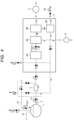
- FIG. 3 a system flow at the time of replenishing the ammonia tank 1 with ammonia is illustrated.
- the produced nitrogen is pressurized and stored in the nitrogen tank 5.
- the internal combustion engine 8 is stopped at the time of replenishment of fuel, and hence no hydrogen is supplied to the internal combustion engine 8.
- a control valve V4 in the fuel pipe purge line 11 is closed, and no nitrogen is supplied to the hydrogen supply line 7.
- the cargo hold 9 is purged with nitrogen from the cargo hold purge line 12 also at the time of replenishment of fuel. This is because it is always required to purge flammable substances and the like with an inert gas.
- ammonia tank 1 is purged with nitrogen from the tank purge line 13 also at the time of replenishment of fuel. That is, the ammonia tank 1 and the ammonia supply line 2 are subjected to inerting with nitrogen before being ventilated with dry air in order to avoid the formation of an explosive hazardous atmosphere inside the ammonia tank 1 and the ammonia supply line 2.
- liquid ammonia anhydrous has the risk of generating static electricity, which may serve as an ignition source, and hence care should be taken so as not to spray the liquid ammonia into the empty ammonia tank 1 in which air is present.
- the residual ammonia is liquefied by a reliquefaction device 4D arranged on a downstream side of the nitrogen separation PSA device 4B, and the residual nitrogen is separated at the time of this liquefaction. Then, the residual ammonia is reduced to an upstream side of the vaporizer 3 as liquid ammonia.
- the reliquefaction device 4D used in Example 1 is formed of a compressor. Ammonia can be liquefied by being pressurized to 8 atmospheres or more at room temperature, and hence ammonia is easily liquefied in the reliquefaction device 4D.
- the reliquefaction device 4D is provided with a safety valve V5 for safety.
- Example 1 of the present invention has a configuration in which the purity of hydrogen is about 90% and the balance contains about 10% nitrogen.
- the residual ammonia is completely removed, and high-purity hydrogen and some nitrogen are supplied to the internal combustion engine 8. Then, in the entire operating range of the internal combustion engine 8, the internal combustion engine 8 generates power through use of, as fuel, only the hydrogen produced by the reformer 4 of the hydrogen production device A.
- the produced nitrogen can be utilized as the purge gas, and hence there is obtained an excellent effect in that it is not required to provide an additional nitrogen production device or nitrogen container.
- Example 1 the purity of hydrogen is high. Because of this, a fuel cell and a prime mover may be provided instead of the internal combustion engine 8 so that the fuel cell may generate electricity through use of only the hydrogen produced by the reformer 4 of the hydrogen production device A, and the prime mover may be driven with this electricity to generate power. Thus, in Example 1, high-purity hydrogen is combusted, and hence greenhouse gas emission can be reduced to almost zero.
- Example 2 of the present invention is described with reference to FIG. 5 .
- FIG. 5 a configuration of a periphery of a reformer 24 in Example 2 is illustrated.
- the ammonia vaporized by the vaporizer 3 is reformed in a catalyst tank 24A in the reformer 24, and the reformed gas contains hydrogen, nitrogen, and residual ammonia.
- the residual ammonia in the reformed gas is liquefied by a reliquefaction device 24D arranged on a downstream side of the catalyst tank 24A, and is reduced to an upstream side of the vaporizer 3 as liquid ammonia.
- the reliquefaction device 24D used in Example 2 is formed of a cooler. Ammonia can be liquefied by being cooled to, for example, -33°C or less, and hence ammonia is easily liquefied by the reliquefaction device 24D.
- the gas containing hydrogen and nitrogen that has passed through the reliquefaction device 24D has hydrogen separated therefrom by a hydrogen separation PSA device 24C arranged on a downstream side of the reliquefaction device 24D, and the separated hydrogen is fed from a hydrogen output pipe of the hydrogen separation PSA device 24C to the hydrogen tank 6.
- Example 2 of the present invention also has a configuration in which the purity of hydrogen is about 90% and the balance contains about 10% nitrogen. The residual ammonia is completely removed, and high-purity hydrogen and some nitrogen are supplied to the internal combustion engine 8. Also in Example 2 of the present invention, the same effects as those in Example 1 are obtained.
- Example 3 Only nitrogen cannot be separated by PSA from the gas containing hydrogen and nitrogen that has passed through a reliquefaction device 34D, and hence the nitrogen membrane separation device 34B using membrane separation is used in Example 3. Then, nitrogen is separated by the nitrogen membrane separation device 34B arranged on a downstream side of the reliquefaction device 34D, and the separated nitrogen is fed from a nitrogen output pipe of the nitrogen membrane separation device 34B to the nitrogen tank 5.
- the gas that has not been separated by the nitrogen membrane separation device 34B contains hydrogen, and this gas is fed from an output pipe different from the nitrogen output pipe of the nitrogen membrane separation device 34B to the hydrogen tank 6.
- Example 3 of the present invention also has a configuration in which the purity of hydrogen is about 90% and the balance contains about 10% nitrogen. The residual ammonia is completely removed, and high-purity hydrogen and some nitrogen are supplied to the internal combustion engine 8. Also in Example 3 of the present invention, the same effects as those in Example 1 are obtained.
- Example 4 of the present invention is described with reference to FIG. 7 .
- FIG. 7 a configuration of a periphery of a reformer 44 in Example 4 is illustrated.
- the ammonia vaporized by the vaporizer 3 is reformed in a catalyst tank 44A in the reformer 44, and the reformed gas contains hydrogen, nitrogen, and residual ammonia.
- Example 4 has a configuration in which the reliquefaction device 34D in Example 3 is omitted.
- the gas that has not been separated by the nitrogen membrane separation device 44B contains hydrogen and residual ammonia, and this gas is fed from an output pipe different from the nitrogen output pipe of the nitrogen membrane separation device 44B to the hydrogen tank 6.
- Example 4 of the present invention has a configuration in which the purity of hydrogen is about 90% and the balance contains about 1% to 10% nitrogen, with several percent of residual ammonia remaining. High-purity hydrogen, some nitrogen, and a small amount of residual ammonia are supplied to the internal combustion engine 8, resulting in co-combustion of hydrogen and ammonia. That is, the internal combustion engine 8 co-combusts the hydrogen produced by the reformer 44 of the hydrogen production device A and the residual ammonia to generate power.
- a simple apparatus as in Example 4 enables flame-retardant ammonia to be easily co-combusted.
- high-purity hydrogen is combusted, and hence greenhouse gas emission can be suppressed to be significantly low.
- GHG zero emission can be achieved even with co-combustion of ammonia in the configuration of Example 4.
- nitrogen obtained by reforming ammonia it is not required to separately provide a nitrogen gas production device, and the space of a hull can be effectively utilized.
Landscapes
- Engineering & Computer Science (AREA)
- Chemical & Material Sciences (AREA)
- Combustion & Propulsion (AREA)
- Mechanical Engineering (AREA)
- Ocean & Marine Engineering (AREA)
- Chemical Kinetics & Catalysis (AREA)
- General Chemical & Material Sciences (AREA)
- Sustainable Development (AREA)
- Life Sciences & Earth Sciences (AREA)
- Sustainable Energy (AREA)
- Organic Chemistry (AREA)
- Electrochemistry (AREA)
- Manufacturing & Machinery (AREA)
- Oil, Petroleum & Natural Gas (AREA)
- General Engineering & Computer Science (AREA)
- Health & Medical Sciences (AREA)
- General Health & Medical Sciences (AREA)
- Inorganic Chemistry (AREA)
- Power Engineering (AREA)
- Transportation (AREA)
- Output Control And Ontrol Of Special Type Engine (AREA)
- Filling Or Discharging Of Gas Storage Vessels (AREA)
- Fuel Cell (AREA)
Applications Claiming Priority (2)
| Application Number | Priority Date | Filing Date | Title |
|---|---|---|---|
| JP2022037181A JP7105021B1 (ja) | 2022-03-10 | 2022-03-10 | 輸送機器 |
| PCT/JP2022/012280 WO2023170983A1 (fr) | 2022-03-10 | 2022-03-17 | Machine de transport |
Publications (2)
| Publication Number | Publication Date |
|---|---|
| EP4265515A1 true EP4265515A1 (fr) | 2023-10-25 |
| EP4265515A4 EP4265515A4 (fr) | 2024-12-18 |
Family
ID=82493178
Family Applications (1)
| Application Number | Title | Priority Date | Filing Date |
|---|---|---|---|
| EP22818162.4A Pending EP4265515A4 (fr) | 2022-03-10 | 2022-03-17 | Machine de transport |
Country Status (6)
| Country | Link |
|---|---|
| US (1) | US12401051B2 (fr) |
| EP (1) | EP4265515A4 (fr) |
| JP (1) | JP7105021B1 (fr) |
| KR (1) | KR102939976B1 (fr) |
| CN (1) | CN117043059A (fr) |
| WO (1) | WO2023170983A1 (fr) |
Families Citing this family (9)
| Publication number | Priority date | Publication date | Assignee | Title |
|---|---|---|---|---|
| US11994061B2 (en) | 2021-05-14 | 2024-05-28 | Amogy Inc. | Methods for reforming ammonia |
| KR102814660B1 (ko) * | 2022-08-03 | 2025-05-29 | 삼성중공업 주식회사 | 암모니아 연료 선박 |
| WO2024081632A1 (fr) * | 2022-10-11 | 2024-04-18 | Amogy Inc. | Systèmes et procédés de traitement d'ammoniac |
| JP2024100164A (ja) * | 2023-01-13 | 2024-07-26 | 愛三工業株式会社 | 燃料供給装置 |
| WO2024241359A1 (fr) * | 2023-05-19 | 2024-11-28 | 株式会社セイブ・ザ・プラネット | Procédé d'allumage |
| CN121712846A (zh) | 2023-08-14 | 2026-03-20 | 佳能株式会社 | 树脂组合物、树脂组合物的制造方法、粒料、成形体、注射成形体和设备 |
| GB2635309A (en) * | 2023-09-14 | 2025-05-14 | Lge Ip Man Company Limited | Method and system for recovering fuel from an engine |
| JP7848252B2 (ja) * | 2024-01-22 | 2026-04-20 | 株式会社三井E&S | 高圧水素ガス配管からの水素ガス漏洩検知システム |
| US20250327427A1 (en) * | 2024-04-17 | 2025-10-23 | Caterpillar Inc. | Systems and methods for venting a pressurized fluid used as a fuel in an engine |
Family Cites Families (13)
| Publication number | Priority date | Publication date | Assignee | Title |
|---|---|---|---|---|
| JPS62256088A (ja) | 1986-04-30 | 1987-11-07 | Toshiba Corp | 画像処理装置 |
| US8272353B2 (en) * | 2008-02-19 | 2012-09-25 | University Of Ontario Institute Of Technology | Apparatus for using ammonia as a sustainable fuel, refrigerant and NOx reduction agent |
| DE102010006153A1 (de) * | 2010-01-29 | 2011-08-04 | Siemens Aktiengesellschaft, 80333 | Elektrisch angetriebenes Luftfahrzeug |
| JP6566639B2 (ja) * | 2015-01-05 | 2019-08-28 | 大阪瓦斯株式会社 | 水素製造装置の運転方法および水素製造装置 |
| JP5870341B1 (ja) * | 2015-05-29 | 2016-02-24 | 株式会社フクハラ | 舶用防爆パージガス供給システム |
| KR102234540B1 (ko) * | 2017-05-11 | 2021-03-31 | 삼성중공업 주식회사 | 동력발생장치 |
| NO343554B1 (no) * | 2017-08-14 | 2019-04-01 | Lars Harald Heggen | Nullutslipps fremdriftssystem og generatoranlegg med ammoniakk som brennstoff |
| JP6999627B2 (ja) | 2019-11-12 | 2022-01-18 | 東京応化工業株式会社 | 化学増幅型感光性組成物の製造方法 |
| KR102755813B1 (ko) * | 2020-05-13 | 2025-01-20 | 한화오션 주식회사 | 선박용 연료 공급 시스템 |
| KR102755885B1 (ko) * | 2020-05-22 | 2025-01-20 | 한화오션 주식회사 | 선박용 연료 공급 시스템 |
| JP6859475B1 (ja) | 2020-08-06 | 2021-04-14 | 三菱造船株式会社 | 船舶 |
| KR102298854B1 (ko) * | 2021-01-27 | 2021-09-09 | 주식회사 트랜스가스솔루션 | 선박의 연료 공급 시스템 |
| CN113623089B (zh) * | 2021-08-11 | 2023-01-24 | 中国船舶重工集团柴油机有限公司 | 一种船用氨供给系统及船舶 |
-
2022
- 2022-03-10 JP JP2022037181A patent/JP7105021B1/ja active Active
- 2022-03-17 KR KR1020227043841A patent/KR102939976B1/ko active Active
- 2022-03-17 CN CN202280005103.XA patent/CN117043059A/zh active Pending
- 2022-03-17 EP EP22818162.4A patent/EP4265515A4/fr active Pending
- 2022-03-17 WO PCT/JP2022/012280 patent/WO2023170983A1/fr not_active Ceased
- 2022-03-17 US US18/010,984 patent/US12401051B2/en active Active
Also Published As
| Publication number | Publication date |
|---|---|
| JP7105021B1 (ja) | 2022-07-22 |
| US20240234769A1 (en) | 2024-07-11 |
| KR20230133756A (ko) | 2023-09-19 |
| EP4265515A4 (fr) | 2024-12-18 |
| JP2023132069A (ja) | 2023-09-22 |
| US12401051B2 (en) | 2025-08-26 |
| KR102939976B1 (ko) | 2026-03-16 |
| CN117043059A (zh) | 2023-11-10 |
| WO2023170983A1 (fr) | 2023-09-14 |
Similar Documents
| Publication | Publication Date | Title |
|---|---|---|
| EP4265515A1 (fr) | Machine de transport | |
| CN102666269B (zh) | 具有用于气体燃料的燃料罐的集装箱船 | |
| KR102856823B1 (ko) | 선박의 통합형 가스 생성 시스템 및 방법 | |
| KR20230136859A (ko) | 액화수소 운반선 | |
| KR102783834B1 (ko) | 선박용 연료 공급 시스템 | |
| KR20210141817A (ko) | 선박용 연료 공급 시스템 | |
| JP2011178250A (ja) | イナートガス貯蔵・供給システムおよび方法 | |
| KR102781718B1 (ko) | 선박용 연료 공급 시스템 | |
| KR102713857B1 (ko) | 부유식 저장 발전 설비 | |
| KR102559318B1 (ko) | Fsru 및 lngc로 용도 변경이 가능한 선박 | |
| JP7519136B1 (ja) | メタノール燃料船 | |
| KR102926404B1 (ko) | Lng 연료 추진 컨테이너 선박의 배치구조 및 상기 lng 연료 추진 컨테이너 선박의 증발가스 처리 시스템 | |
| KR102756235B1 (ko) | 증발가스를 이용한 수소발생시스템 | |
| KR20240123855A (ko) | 암모니아 수소 혼소엔진을 추진 동력원으로 하는 액화수소 운반선 | |
| KR20240041059A (ko) | 이종화물 선적선 | |
| KR102725831B1 (ko) | 부유식 저장 분해 설비 | |
| KR102697408B1 (ko) | 부유식 저장 발전 설비 | |
| KR102697412B1 (ko) | 부유식 저장 발전 설비 | |
| KR102808422B1 (ko) | 선박의 연료전지용 암모니아 연료 공급 시스템 | |
| KR102715407B1 (ko) | 부유식 저장 발전 설비 | |
| KR102937870B1 (ko) | 연료전지용 암모니아 회수 시스템 및 방법 | |
| KR102377797B1 (ko) | 휘발성 유기화합물 처리 시스템 및 선박 | |
| KR20260049925A (ko) | 연료전지용 연료공급시스템 및 이를 이용한 연료전지 추진 선박 | |
| KR20230096201A (ko) | 액화가스 운반선의 연료공급시스템 | |
| KR20260051121A (ko) | 연료전지 추진 선박 |
Legal Events
| Date | Code | Title | Description |
|---|---|---|---|
| STAA | Information on the status of an ep patent application or granted ep patent |
Free format text: STATUS: UNKNOWN |
|
| STAA | Information on the status of an ep patent application or granted ep patent |
Free format text: STATUS: THE INTERNATIONAL PUBLICATION HAS BEEN MADE |
|
| PUAI | Public reference made under article 153(3) epc to a published international application that has entered the european phase |
Free format text: ORIGINAL CODE: 0009012 |
|
| STAA | Information on the status of an ep patent application or granted ep patent |
Free format text: STATUS: REQUEST FOR EXAMINATION WAS MADE |
|
| 17P | Request for examination filed |
Effective date: 20221215 |
|
| AK | Designated contracting states |
Kind code of ref document: A1 Designated state(s): AL AT BE BG CH CY CZ DE DK EE ES FI FR GB GR HR HU IE IS IT LI LT LU LV MC MK MT NL NO PL PT RO RS SE SI SK SM TR |
|
| A4 | Supplementary search report drawn up and despatched |
Effective date: 20241118 |
|
| RIC1 | Information provided on ipc code assigned before grant |
Ipc: B63B 17/00 20060101ALN20241112BHEP Ipc: B63H 21/00 20060101ALN20241112BHEP Ipc: F02M 25/00 20060101ALN20241112BHEP Ipc: B63J 3/00 20060101ALN20241112BHEP Ipc: B63J 3/02 20060101ALI20241112BHEP Ipc: B63B 25/08 20060101ALI20241112BHEP Ipc: B63H 21/38 20060101ALI20241112BHEP Ipc: C01B 3/04 20060101ALI20241112BHEP Ipc: H01M 8/22 20060101ALI20241112BHEP Ipc: F02M 21/02 20060101ALI20241112BHEP Ipc: B60L 50/70 20190101ALI20241112BHEP Ipc: B63H 21/17 20060101ALI20241112BHEP Ipc: B63H 21/14 20060101AFI20241112BHEP |
|
| DAV | Request for validation of the european patent (deleted) | ||
| DAX | Request for extension of the european patent (deleted) |