EP4265521B1 - Klimaregelungssystem mit luftbetriebener pumpe - Google Patents
Klimaregelungssystem mit luftbetriebener pumpe Download PDFInfo
- Publication number
- EP4265521B1 EP4265521B1 EP23168920.9A EP23168920A EP4265521B1 EP 4265521 B1 EP4265521 B1 EP 4265521B1 EP 23168920 A EP23168920 A EP 23168920A EP 4265521 B1 EP4265521 B1 EP 4265521B1
- Authority
- EP
- European Patent Office
- Prior art keywords
- medium
- heat exchanger
- ram air
- secondary fluid
- control system
- Prior art date
- Legal status (The legal status is an assumption and is not a legal conclusion. Google has not performed a legal analysis and makes no representation as to the accuracy of the status listed.)
- Active
Links
Images
Classifications
-
- B—PERFORMING OPERATIONS; TRANSPORTING
- B64—AIRCRAFT; AVIATION; COSMONAUTICS
- B64D—EQUIPMENT FOR FITTING IN OR TO AIRCRAFT; FLIGHT SUITS; PARACHUTES; ARRANGEMENT OR MOUNTING OF POWER PLANTS OR PROPULSION TRANSMISSIONS IN AIRCRAFT
- B64D13/00—Arrangements or adaptations of air-treatment apparatus for aircraft crew or passengers, or freight space
- B64D13/06—Arrangements or adaptations of air-treatment apparatus for aircraft crew or passengers, or freight space the air being conditioned
-
- B—PERFORMING OPERATIONS; TRANSPORTING
- B60—VEHICLES IN GENERAL
- B60H—ARRANGEMENTS OF HEATING, COOLING, VENTILATING OR OTHER AIR-TREATING DEVICES SPECIALLY ADAPTED FOR PASSENGER OR GOODS SPACES OF VEHICLES
- B60H1/00—Heating, cooling or ventilating devices
- B60H1/00321—Heat exchangers for air-conditioning devices
- B60H1/00328—Heat exchangers for air-conditioning devices of the liquid-air type
-
- B—PERFORMING OPERATIONS; TRANSPORTING
- B64—AIRCRAFT; AVIATION; COSMONAUTICS
- B64D—EQUIPMENT FOR FITTING IN OR TO AIRCRAFT; FLIGHT SUITS; PARACHUTES; ARRANGEMENT OR MOUNTING OF POWER PLANTS OR PROPULSION TRANSMISSIONS IN AIRCRAFT
- B64D13/00—Arrangements or adaptations of air-treatment apparatus for aircraft crew or passengers, or freight space
- B64D13/06—Arrangements or adaptations of air-treatment apparatus for aircraft crew or passengers, or freight space the air being conditioned
- B64D2013/0603—Environmental Control Systems
- B64D2013/0618—Environmental Control Systems with arrangements for reducing or managing bleed air, using another air source, e.g. ram air
-
- B—PERFORMING OPERATIONS; TRANSPORTING
- B64—AIRCRAFT; AVIATION; COSMONAUTICS
- B64D—EQUIPMENT FOR FITTING IN OR TO AIRCRAFT; FLIGHT SUITS; PARACHUTES; ARRANGEMENT OR MOUNTING OF POWER PLANTS OR PROPULSION TRANSMISSIONS IN AIRCRAFT
- B64D13/00—Arrangements or adaptations of air-treatment apparatus for aircraft crew or passengers, or freight space
- B64D13/06—Arrangements or adaptations of air-treatment apparatus for aircraft crew or passengers, or freight space the air being conditioned
- B64D2013/0603—Environmental Control Systems
- B64D2013/064—Environmental Control Systems comprising more than one system, e.g. dual systems
-
- B—PERFORMING OPERATIONS; TRANSPORTING
- B64—AIRCRAFT; AVIATION; COSMONAUTICS
- B64D—EQUIPMENT FOR FITTING IN OR TO AIRCRAFT; FLIGHT SUITS; PARACHUTES; ARRANGEMENT OR MOUNTING OF POWER PLANTS OR PROPULSION TRANSMISSIONS IN AIRCRAFT
- B64D13/00—Arrangements or adaptations of air-treatment apparatus for aircraft crew or passengers, or freight space
- B64D13/06—Arrangements or adaptations of air-treatment apparatus for aircraft crew or passengers, or freight space the air being conditioned
- B64D2013/0603—Environmental Control Systems
- B64D2013/0648—Environmental Control Systems with energy recovery means, e.g. using turbines
-
- B—PERFORMING OPERATIONS; TRANSPORTING
- B64—AIRCRAFT; AVIATION; COSMONAUTICS
- B64D—EQUIPMENT FOR FITTING IN OR TO AIRCRAFT; FLIGHT SUITS; PARACHUTES; ARRANGEMENT OR MOUNTING OF POWER PLANTS OR PROPULSION TRANSMISSIONS IN AIRCRAFT
- B64D13/00—Arrangements or adaptations of air-treatment apparatus for aircraft crew or passengers, or freight space
- B64D13/06—Arrangements or adaptations of air-treatment apparatus for aircraft crew or passengers, or freight space the air being conditioned
- B64D2013/0603—Environmental Control Systems
- B64D2013/0662—Environmental Control Systems with humidity control
-
- B—PERFORMING OPERATIONS; TRANSPORTING
- B64—AIRCRAFT; AVIATION; COSMONAUTICS
- B64D—EQUIPMENT FOR FITTING IN OR TO AIRCRAFT; FLIGHT SUITS; PARACHUTES; ARRANGEMENT OR MOUNTING OF POWER PLANTS OR PROPULSION TRANSMISSIONS IN AIRCRAFT
- B64D13/00—Arrangements or adaptations of air-treatment apparatus for aircraft crew or passengers, or freight space
- B64D13/06—Arrangements or adaptations of air-treatment apparatus for aircraft crew or passengers, or freight space the air being conditioned
- B64D2013/0603—Environmental Control Systems
- B64D2013/0674—Environmental Control Systems comprising liquid subsystems
-
- F—MECHANICAL ENGINEERING; LIGHTING; HEATING; WEAPONS; BLASTING
- F28—HEAT EXCHANGE IN GENERAL
- F28F—DETAILS OF HEAT-EXCHANGE AND HEAT-TRANSFER APPARATUS, OF GENERAL APPLICATION
- F28F2250/00—Arrangements for modifying the flow of the heat exchange media, e.g. flow guiding means; Particular flow patterns
- F28F2250/08—Fluid driving means, e.g. pumps, fans
-
- Y—GENERAL TAGGING OF NEW TECHNOLOGICAL DEVELOPMENTS; GENERAL TAGGING OF CROSS-SECTIONAL TECHNOLOGIES SPANNING OVER SEVERAL SECTIONS OF THE IPC; TECHNICAL SUBJECTS COVERED BY FORMER USPC CROSS-REFERENCE ART COLLECTIONS [XRACs] AND DIGESTS
- Y02—TECHNOLOGIES OR APPLICATIONS FOR MITIGATION OR ADAPTATION AGAINST CLIMATE CHANGE
- Y02T—CLIMATE CHANGE MITIGATION TECHNOLOGIES RELATED TO TRANSPORTATION
- Y02T50/00—Aeronautics or air transport
- Y02T50/50—On board measures aiming to increase energy efficiency
Definitions
- Embodiments of the present disclosure relate to an environmental control system for an aircraft, and more particularly, to an environmental control system including a pump driven by an air flow.
- Aircraft that fly at altitudes above that at which ambient air is suitable for the health and comfort of crew and passengers are often equipped with environmental air conditioning systems. Such systems provide pressurized conditioned air for cooling passengers, crew, and other aircraft systems and components. These air conditioning systems typically use high pressure air bled from a turbine engine or auxiliary power unit (APU). This high-pressure air is typically at a temperature and pressure far in excess of the temperature and pressure required for conditioned air to be supplied to the cockpit and passenger cabin, so it must be expanded and cooled by the air conditioning system before it can be discharged into the aircraft cabin as conditioned air.
- APU auxiliary power unit
- the high-pressure air bled from a turbine engine or auxiliary power unit is typically cooled within the air conditioning system by rejecting heat therefrom directly to a ram air circuit.
- engine bleed air increases the overall fuel burn of the system and ram air heat exchangers typically must be large to provide an acceptable heat sink for cooling the bleed air.
- US 2013/0160472 A1 describes an aircraft air conditioning system.
- US 5,918,472 describes an air cycle environmental control system.
- US 4,553,407 describes a high efficiency air cycle air conditioning system.
- EP 3 835 208 A1 describes a bootstrap air cycle with vapour power turbine.
- An environmental control system of a vehicle includes an inlet configured to receive a medium, a heat exchanger fluidly connected to the inlet to receive the medium, a water separator arranged directly downstream from the heat exchanger relative to a flow of the medium, and a ram air circuit including another inlet configured to receive ram air and including a ram air heat exchanger.
- a closed secondary fluid loop is operably coupled to the heat exchanger and to the ram air heat exchanger.
- the secondary fluid loop has a secondary fluid circulating therein that removes heat from the medium in the heat exchanger and that discharges heat to the ram air in the ram air heat exchanger.
- the secondary fluid is a liquid, optionally
- system comprises an expansion device, the expansion device being operably coupled to the heat exchanger and to the ram air circuit.
- the expansion device further comprises a turbine and a fan operably coupled by a shaft, the turbine being arranged to receive the medium from the heat exchanger, and the fan being arranged within the ram air circuit.
- the expansion device further comprises a pump mounted to the shaft, the pump being arranged within the secondary fluid loop, wherein work extracted by the turbine is transferred to the pump via the shaft.
- the ram air is not arranged in a direct heat exchange relationship with the medium.
- the medium is bleed air.
- the vehicle is an aircraft.
- a method of operating an environmental control system of a vehicle includes receiving a medium at an inlet for delivery to one or more loads at a heat exchanger, the heat exchanger being directly downstream from the inlet and removing water from the medium within a water extractor located directly downstream from the heat exchanger relative to a flow of the medium, circulating a secondary fluid within a secondary fluid loop operably coupled to the heat exchanger and a ram air circuit, cooling the medium by removing heat from the medium via the secondary fluid at the heat exchanger, and discharging heat from the secondary fluid to a ram air within the ram air circuit.
- the method comprises extracting energy from the medium and driving a pump using the energy extracted from the medium, the circulating of the secondary fluid being performed by the pump.
- the method comprises extracting energy from the medium; and driving a fan arranged within the ram air circuit using the energy extracted from the medium.
- the method comprises moving the ram air through the ram air circuit in response to driving the fan.
- the secondary fluid is a liquid.
- the secondary fluid is water.
- the medium is bleed air.
- the vehicle is an aircraft.
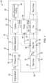
- FIG. 1 is a schematic diagram of an environmental control system of a vehicle according to an embodiment.
- an environmental control system such as an air conditioning unit or pack for example
- the environmental control system 20 may be configured to receive a medium A at an inlet 22 and provide a conditioned form of the medium A to one or more loads 24.
- the medium A may be bleed air, which is pressurized air originating from, i.e., being "bled" from, an engine or auxiliary power unit of the aircraft. It shall be understood that one or more of the temperature, humidity, and pressure of the bleed air can vary based upon the compressor stage and revolutions per minute of the engine or auxiliary power unit from which the air is drawn.
- the environmental control system 20 may include a ram air circuit 30 including a shell or duct 32 within which one or more heat exchangers are located.
- the ram air duct 32 can receive a medium R A , such as ram air for example, at an inlet 34 and can direct the medium R A through a portion of the ECS 20.
- the ram air R A may be ambient air from outside the aircraft.
- the one or more heat exchangers are devices built for efficient heat transfer from one medium to another. Examples of the type of heat exchangers that may be used, include, but are not limited to, double pipe, shell and tube, plate, plate and shell, adiabatic shell, plate fin, pillow plate, and fluid heat exchangers.
- the one or more heat exchangers arranged within the ram air duct 32 may be referred to as ram heat exchangers.
- the ram air circuit 30 includes a single heat exchanger 36.
- ram air R A such as outside air for example, acts as a heat sink to cool another medium passing there through.
- the ECS 20 additionally includes an expansion device 40.
- the expansion device 40 of the ECS 20 is a mechanical device that includes components for performing thermodynamic work on one or more mediums (e.g., extracts work from or applies work to a medium A by raising and/or lowering pressure and by raising and/or lowering temperature).
- Examples of the expansion device 40 include, but are not limited to, an air cycle machine, such as a three-wheel or four-wheel air cycle machine.
- the compression device is a simple cycle or two-wheel air cycle machine.
- the expansion device 40 includes a turbine 42 and a fan 44 operably coupled to one another via a shaft 46.
- the turbine 42 is a mechanical device that expands a medium and extracts work therefrom (also referred to as extracting energy).
- the turbine 42 drives the fan 44 via the shaft 46.
- a fan 44 is a mechanical device that can force via push or pull methods air through the ram air duct 32, across at least a portion of one or more ram air heat exchangers 36.
- the fan 44 is a component separate from the expansion device and is driven by any suitable means are also contemplated herein.
- the ECS 20 additionally includes one or more heat exchangers or devices configured to provide efficient heat transfer from one medium to another.
- the ECS 20 includes a single heat exchanger 48 arranged directly downstream from the inlet 22 of the medium A.
- additional heat exchangers or other components at any suitable location relative to the flow of medium A or the flow of ram air R A are also within the scope of the disclosure.
- the ram air R A is not arranged in a direct heat exchange relationship with the medium A at either the heat exchanger 48 or the ram air heat exchanger 36. Rather, the ECS 20 uses a secondary fluid W circulating through a closed secondary fluid loop 50 to condition both the medium A and the ram air R A .
- the secondary fluid W is a liquid, such as water or another suitable liquid for example.
- a pump 52 may be used to circulate the secondary fluid W through the secondary fluid loop 50.
- the pump is 52 mounted to the shaft 46 of the expansion device 40 as a third wheel and is therefore driven by rotation of the shaft 46 resulting from work or energy extracted from the medium A within the turbine 42.
- the secondary fluid loop 50 is thermally coupled to both the heat exchanger 48 and the ram air heat exchanger 36.
- the heat exchanger 48 includes a secondary fluid inlet 54 and a secondary fluid outlet 56.
- the secondary fluid inlet 54 may be connected to an outlet 58 of the pump 52 by a conduit 60.
- the ram air heat exchanger 36 includes a secondary fluid inlet 62 connected to the secondary fluid outlet 56 of the heat exchanger 48 by a conduit 64.
- the secondary fluid outlet 66 of the ram air heat exchanger 36 is fluidly coupled to an inlet 68 of the pump 52 by a conduit 70.
- the medium A is provided to the ECS 20 via the inlet 22. From the inlet 22, the medium A is delivered to the heat exchanger 48. Within the heat exchanger 48, heat transfers from the medium A to the secondary fluid W. The resulting cooled medium A may then be provided to a downstream water separator or extractor 72.
- the heat exchanger 48 is configured as a condenser such that as the medium A cools therein, the water entrained within the medium A will condense. This condensed fluid may then be removed from the medium A within the water extractor 72. The condensed fluid, for example water, removed from the medium A may be reused elsewhere on the aircraft. In the illustrated, non-limiting embodiment, the water is sprayed on the face of the ram air heat exchanger 36.
- the dry medium A is provided to an inlet of the turbine 42.
- the medium A is expanded, and work is extracted therefrom which results in a cooling and depressurization of the medium A.
- the cooler and lower pressure medium A provided at an outlet of the turbine 42 may then be delivered to one or more loads of the vehicle.
- the work extracted from the medium A within the turbine 42 drives the pump 52 causing the secondary fluid W to circulate within the secondary fluid loop 50.
- the work extracted form the medium A within the turbine 42 also drives rotation of the fan 44.
- ram air R A from the inlet 26 moves through the ram air duct 32, and specifically, across the ram air heat exchanger 36.
- the heated secondary fluid W output from the heat exchanger 48 is provided to the secondary fluid inlet 62 of the ram air heat exchanger 36.
- heat from the secondary fluid W is transferred to the ram air R A .
- the heated ram air R A is then exhausted overboard from an outlet of the ram air duct 32.
- An environmental control system 20 as described herein relies on a secondary fluid to remove heat from the medium A and then discharge that heat to the flow of ram air R A . Because the ability to transfer heat is significantly increased in liquid-air heat exchangers compared to air-air heat exchangers, inclusion of the secondary fluid loop results not only in an improved ability to discharge heat to the ram air R A , but also the potential to achieve cooler air temperatures at the outlet of the heat exchanger 48. Additionally, the energy required to increase a fluid's pressure via a pump is significantly less than required to increase the pressure of a gaseous medium (such as air) via a compressor which may allow for heat exchanger designs with more heat transfer surface area on the liquid sides relative to an air-air heat exchanger.
- a gaseous medium such as air
Landscapes
- Health & Medical Sciences (AREA)
- General Health & Medical Sciences (AREA)
- Pulmonology (AREA)
- Engineering & Computer Science (AREA)
- Aviation & Aerospace Engineering (AREA)
- Engine Equipment That Uses Special Cycles (AREA)
Claims (13)
- Klimaregelungssystem eines Fahrzeugs, umfassend:einen Einlass (22), der dazu konfiguriert ist, ein Medium aufzunehmen;einen Wärmetauscher (48), der direkt mit dem Einlass fluidverbunden ist, um das Medium aufzunehmen; und einen Wasserabscheider (72);einen Stauluftkreislauf (30), der einen weiteren Einlass (34) beinhaltet, der dazu konfiguriert ist, Stauluft aufzunehmen, und einen Stauluft-Wärmetauscher (36) beinhaltet; undein geschlossenes sekundäres Fluidumlaufsystem (50), das an den Wärmetauscher (48) und den Stauluft-Wärmetauscher (36) wirkgekoppelt ist, wobei in dem sekundären Fluidumlaufsystem ein sekundäres Fluid zirkuliert, das Wärme aus dem Medium in dem Wärmetauscher (48) entnimmt und Wärme an die Stauluft in dem Stauluft-Wärmetauscher (36) abführt, dadurch gekennzeichnet, dass der Wasserabscheider relativ zu einer Strömung des Mediums direkt stromabwärts von dem Wärmetauscher (48) angeordnet ist.
- Klimaregelungssystem nach Anspruch 1, wobei das sekundäre Fluid eine Flüssigkeit ist und wobei das sekundäre Fluid optional Wasser ist.
- Klimaregelungssystem nach einem der vorhergehenden Ansprüche, ferner umfassend eine Expansionsvorrichtung (40), wobei die Expansionsvorrichtung an den Wärmetauscher (48) und den Stauluftkreislauf (30) wirkgekoppelt ist.
- Klimaregelungssystem nach Anspruch 3, wobei die Expansionsvorrichtung (40) ferner eine Turbine (42) und einen Fan (44) umfasst, die durch eine Welle (46) wirkgekoppelt sind, wobei die Turbine angeordnet ist, um das Medium von dem Wärmetauscher (48) aufzunehmen, und der Fan innerhalb des Stauluftkreislaufs (30) angeordnet ist, und wobei die Expansionsvorrichtung optional ferner eine Pumpe (52) umfasst, die an der Welle montiert ist, wobei die Pumpe innerhalb des sekundären Fluidumlaufsystems angeordnet ist, wobei die durch die Turbine gewonnene Leistung über die Welle an die Pumpe übertragen wird.
- Klimaregelungssystem nach einem der vorhergehenden Ansprüche, wobei die Stauluft nicht in einer direkten Wärmeaustauschbeziehung mit dem Medium angeordnet ist.
- Klimaregelungssystem nach einem vorhergehenden Ansprüche, wobei das Medium Zapfluft ist.
- Klimaregelungssystem nach einem der vorhergehenden Ansprüche, wobei das Fahrzeug ein Luftfahrzeug ist.
- Verfahren zum Betreiben eines Klimaregelungssystems eines Fahrzeugs, umfassend:Aufnehmen eines Mediums an einem Einlass (22) zur Abgabe an einen oder mehrere Verbraucher an einem Wärmetauscher (48);wobei sich der Wärmetauscher direkt stromabwärts von dem Einlass befindet und Wasser aus dem Medium innerhalb eines Wasserextraktors (72) entnimmt, der sich relativ zu einer Strömung des Mediums direkt stromabwärts von dem Wärmetauscher (48) befindet;Zirkulieren eines sekundären Fluids innerhalb eines sekundären Fluidumlaufsystems (50), das an den Wärmetauscher (48) und einen Stauluftkreislauf (30) wirkgekoppelt ist;Kühlen des Mediums durch Entnehmen von Wärme aus dem Medium über das sekundäre Fluid an dem Wärmetauscher (48); undAbführen von Wärme aus dem sekundären Fluid an eine Stauluft innerhalb des Stauluftkreislaufs (30).
- Verfahren nach Anspruch 8, ferner umfassend:Gewinnen von Energie aus dem Medium; undAntreiben einer Pumpe (52) unter Verwendung der aus dem Medium gewonnenen Energie, wobei das Zirkulieren des sekundären Fluids durch die Pumpe durchgeführt wird.
- Verfahren nach Anspruch 8 oder 9, ferner umfassend:Gewinnen von Energie aus dem Medium; undAntreiben eines innerhalb des Stauluftkreislaufs (30) angeordneten Fans unter Verwendung der aus dem Medium gewonnenen Energie, und optional ferner umfassend Bewegen der Stauluft durch den Stauluftkreislauf (30) als Reaktion auf das Antreiben des Fans (44).
- Verfahren nach einem der Ansprüche 8 bis 10, wobei das sekundäre Fluid eine Flüssigkeit ist oder wobei das sekundäre Fluid Wasser ist.
- Verfahren nach einem der Ansprüche 8 bis 11, wobei das Medium Zapfluft ist.
- Verfahren nach einem der Ansprüche 8 bis 12, wobei das Fahrzeug ein Luftfahrzeug ist.
Applications Claiming Priority (1)
| Application Number | Priority Date | Filing Date | Title |
|---|---|---|---|
| US17/725,052 US20230339616A1 (en) | 2022-04-20 | 2022-04-20 | Environmental control system with air powered pump |
Publications (2)
| Publication Number | Publication Date |
|---|---|
| EP4265521A1 EP4265521A1 (de) | 2023-10-25 |
| EP4265521B1 true EP4265521B1 (de) | 2025-04-09 |
Family
ID=86095779
Family Applications (1)
| Application Number | Title | Priority Date | Filing Date |
|---|---|---|---|
| EP23168920.9A Active EP4265521B1 (de) | 2022-04-20 | 2023-04-20 | Klimaregelungssystem mit luftbetriebener pumpe |
Country Status (2)
| Country | Link |
|---|---|
| US (1) | US20230339616A1 (de) |
| EP (1) | EP4265521B1 (de) |
Families Citing this family (1)
| Publication number | Priority date | Publication date | Assignee | Title |
|---|---|---|---|---|
| US20230080053A1 (en) * | 2021-09-10 | 2023-03-16 | Hamilton Sundstrand Corporation | Cryogenic fluid heat exchanger system for an aircraft environmental control system (ecs) |
Family Cites Families (10)
| Publication number | Priority date | Publication date | Assignee | Title |
|---|---|---|---|---|
| US4553407A (en) * | 1983-12-12 | 1985-11-19 | United Technologies Corporation | High efficiency air cycle air conditioning system |
| WO1999002401A1 (en) * | 1997-07-11 | 1999-01-21 | Alliedsignal Inc. | Air cycle environmental control system with vapor cycle system assisted condensation |
| DE102010034830B4 (de) * | 2010-08-19 | 2012-11-08 | Airbus Operations Gmbh | Klimatisierungssystems für ein Luftfahrzeug mit separatem Kältekreis |
| FR3065518B1 (fr) * | 2017-04-20 | 2019-07-05 | Liebherr-Aerospace Toulouse Sas | Procede et dispositif de controle thermique d'une pluralite de cabines d'un vehicule |
| US11192655B2 (en) * | 2017-11-03 | 2021-12-07 | Hamilton Sundstrand Corporation | Regenerative system ECOECS |
| US10544705B2 (en) * | 2018-03-16 | 2020-01-28 | Hamilton Sundstrand Corporation | Rankine cycle powered by bleed heat |
| US11084592B2 (en) * | 2018-06-26 | 2021-08-10 | Hamilton Sundstrand Corporation | Aircraft environmental control system |
| FR3093325B1 (fr) * | 2019-03-01 | 2021-02-12 | Liebherr Aerospace Toulouse Sas | Système de conditionnement d’air d’une cabine d’aéronef comprenant des moyens de réchauffage de l’eau récoltée par la boucle d’extraction d’eau |
| US11465756B2 (en) * | 2019-12-09 | 2022-10-11 | Hamilton Sundstrand Corporation | Bootstrap air cycle with vapor power turbine |
| US11486315B2 (en) * | 2020-11-06 | 2022-11-01 | Ge Aviation Systems Llc | Combustion engine including turbomachine |
-
2022
- 2022-04-20 US US17/725,052 patent/US20230339616A1/en not_active Abandoned
-
2023
- 2023-04-20 EP EP23168920.9A patent/EP4265521B1/de active Active
Also Published As
| Publication number | Publication date |
|---|---|
| US20230339616A1 (en) | 2023-10-26 |
| EP4265521A1 (de) | 2023-10-25 |
Similar Documents
| Publication | Publication Date | Title |
|---|---|---|
| EP3480113B1 (de) | Regeneratives system ecoecs | |
| EP3489142B1 (de) | Flugzeugumweltkontrollsystem mit zapfluftturbinen in reihe | |
| EP3421364B1 (de) | Dreirädriges und einfaches flugzeug-klimaregelungssystem | |
| EP3470337B1 (de) | Durch zapfluft und kabinenluft angetriebenes zusatzkühlaggregat | |
| EP3943396B1 (de) | Klimaregelungssystem mit optimierter feuchtigkeitsentfernung | |
| EP3395687B1 (de) | Klimaanlage mit einfacher kühlturbine | |
| EP4082910A1 (de) | Vollelektrische ecs mit kabinenabflussgekühlten motorantrieben | |
| US12410949B2 (en) | Ram air turbine powered cabin air compressor | |
| EP4265521B1 (de) | Klimaregelungssystem mit luftbetriebener pumpe | |
| US20240410625A1 (en) | Regeneration using liquid loop of environmental control system | |
| EP4242107A1 (de) | Kühlsystem für ein fahrzeug | |
| EP4342798B1 (de) | Niederdruckluftkreislauf | |
| US12595978B2 (en) | Drain system for ECS water collection | |
| US12078379B2 (en) | Split regeneration environmental control system | |
| EP4725840A1 (de) | Niederdruckluftkreislauf-klimaanlagensteuersystem | |
| US20250305707A1 (en) | Bleedless environmental control system | |
| US20260084824A1 (en) | Series turbine simple cycle ecs | |
| EP4520664A1 (de) | Umweltkontrollsystem mit verringertem ablass | |
| US20250304262A1 (en) | Bleedless environmental control system with motorized air cycle machine | |
| US20250313066A1 (en) | Environmental control system with mixed bleed and ambient pack | |
| US20260103285A1 (en) | Series turbine simple cycle with integrated flow multiplier | |
| US20250304261A1 (en) | Bleedless environmental control system | |
| US20250304264A1 (en) | Environmental control system using architecture with turbines in series | |
| EP3521169B1 (de) | Dreirädrige und einfache flugzeug-klimaanlage |
Legal Events
| Date | Code | Title | Description |
|---|---|---|---|
| STAA | Information on the status of an ep patent application or granted ep patent |
Free format text: STATUS: THE APPLICATION HAS BEEN PUBLISHED |
|
| PUAI | Public reference made under article 153(3) epc to a published international application that has entered the european phase |
Free format text: ORIGINAL CODE: 0009012 |
|
| AK | Designated contracting states |
Kind code of ref document: A1 Designated state(s): AL AT BE BG CH CY CZ DE DK EE ES FI FR GB GR HR HU IE IS IT LI LT LU LV MC ME MK MT NL NO PL PT RO RS SE SI SK SM TR |
|
| STAA | Information on the status of an ep patent application or granted ep patent |
Free format text: STATUS: REQUEST FOR EXAMINATION WAS MADE |
|
| 17P | Request for examination filed |
Effective date: 20240423 |
|
| RBV | Designated contracting states (corrected) |
Designated state(s): AL AT BE BG CH CY CZ DE DK EE ES FI FR GB GR HR HU IE IS IT LI LT LU LV MC ME MK MT NL NO PL PT RO RS SE SI SK SM TR |
|
| GRAP | Despatch of communication of intention to grant a patent |
Free format text: ORIGINAL CODE: EPIDOSNIGR1 |
|
| STAA | Information on the status of an ep patent application or granted ep patent |
Free format text: STATUS: GRANT OF PATENT IS INTENDED |
|
| INTG | Intention to grant announced |
Effective date: 20241105 |
|
| GRAS | Grant fee paid |
Free format text: ORIGINAL CODE: EPIDOSNIGR3 |
|
| GRAA | (expected) grant |
Free format text: ORIGINAL CODE: 0009210 |
|
| STAA | Information on the status of an ep patent application or granted ep patent |
Free format text: STATUS: THE PATENT HAS BEEN GRANTED |
|
| AK | Designated contracting states |
Kind code of ref document: B1 Designated state(s): AL AT BE BG CH CY CZ DE DK EE ES FI FR GB GR HR HU IE IS IT LI LT LU LV MC ME MK MT NL NO PL PT RO RS SE SI SK SM TR |
|
| REG | Reference to a national code |
Ref country code: GB Ref legal event code: FG4D |
|
| REG | Reference to a national code |
Ref country code: CH Ref legal event code: EP |
|
| REG | Reference to a national code |
Ref country code: DE Ref legal event code: R096 Ref document number: 602023002788 Country of ref document: DE |
|
| REG | Reference to a national code |
Ref country code: IE Ref legal event code: FG4D |
|
| PGFP | Annual fee paid to national office [announced via postgrant information from national office to epo] |
Ref country code: DE Payment date: 20250423 Year of fee payment: 3 |
|
| PGFP | Annual fee paid to national office [announced via postgrant information from national office to epo] |
Ref country code: AT Payment date: 20250721 Year of fee payment: 3 |
|
| REG | Reference to a national code |
Ref country code: NL Ref legal event code: MP Effective date: 20250409 |
|
| PG25 | Lapsed in a contracting state [announced via postgrant information from national office to epo] |
Ref country code: NL Free format text: LAPSE BECAUSE OF FAILURE TO SUBMIT A TRANSLATION OF THE DESCRIPTION OR TO PAY THE FEE WITHIN THE PRESCRIBED TIME-LIMIT Effective date: 20250409 |
|
| REG | Reference to a national code |
Ref country code: AT Ref legal event code: MK05 Ref document number: 1783346 Country of ref document: AT Kind code of ref document: T Effective date: 20250409 |
|
| PG25 | Lapsed in a contracting state [announced via postgrant information from national office to epo] |
Ref country code: FI Free format text: LAPSE BECAUSE OF FAILURE TO SUBMIT A TRANSLATION OF THE DESCRIPTION OR TO PAY THE FEE WITHIN THE PRESCRIBED TIME-LIMIT Effective date: 20250409 Ref country code: PT Free format text: LAPSE BECAUSE OF FAILURE TO SUBMIT A TRANSLATION OF THE DESCRIPTION OR TO PAY THE FEE WITHIN THE PRESCRIBED TIME-LIMIT Effective date: 20250811 Ref country code: ES Free format text: LAPSE BECAUSE OF FAILURE TO SUBMIT A TRANSLATION OF THE DESCRIPTION OR TO PAY THE FEE WITHIN THE PRESCRIBED TIME-LIMIT Effective date: 20250409 |
|
| REG | Reference to a national code |
Ref country code: LT Ref legal event code: MG9D |
|
| PG25 | Lapsed in a contracting state [announced via postgrant information from national office to epo] |
Ref country code: GR Free format text: LAPSE BECAUSE OF FAILURE TO SUBMIT A TRANSLATION OF THE DESCRIPTION OR TO PAY THE FEE WITHIN THE PRESCRIBED TIME-LIMIT Effective date: 20250710 Ref country code: NO Free format text: LAPSE BECAUSE OF FAILURE TO SUBMIT A TRANSLATION OF THE DESCRIPTION OR TO PAY THE FEE WITHIN THE PRESCRIBED TIME-LIMIT Effective date: 20250709 |
|
| PG25 | Lapsed in a contracting state [announced via postgrant information from national office to epo] |
Ref country code: PL Free format text: LAPSE BECAUSE OF FAILURE TO SUBMIT A TRANSLATION OF THE DESCRIPTION OR TO PAY THE FEE WITHIN THE PRESCRIBED TIME-LIMIT Effective date: 20250409 |
|
| PG25 | Lapsed in a contracting state [announced via postgrant information from national office to epo] |
Ref country code: BG Free format text: LAPSE BECAUSE OF FAILURE TO SUBMIT A TRANSLATION OF THE DESCRIPTION OR TO PAY THE FEE WITHIN THE PRESCRIBED TIME-LIMIT Effective date: 20250409 |
|
| PG25 | Lapsed in a contracting state [announced via postgrant information from national office to epo] |
Ref country code: HR Free format text: LAPSE BECAUSE OF FAILURE TO SUBMIT A TRANSLATION OF THE DESCRIPTION OR TO PAY THE FEE WITHIN THE PRESCRIBED TIME-LIMIT Effective date: 20250409 |
|
| PG25 | Lapsed in a contracting state [announced via postgrant information from national office to epo] |
Ref country code: AT Free format text: LAPSE BECAUSE OF FAILURE TO SUBMIT A TRANSLATION OF THE DESCRIPTION OR TO PAY THE FEE WITHIN THE PRESCRIBED TIME-LIMIT Effective date: 20250409 |
|
| PG25 | Lapsed in a contracting state [announced via postgrant information from national office to epo] |
Ref country code: RS Free format text: LAPSE BECAUSE OF FAILURE TO SUBMIT A TRANSLATION OF THE DESCRIPTION OR TO PAY THE FEE WITHIN THE PRESCRIBED TIME-LIMIT Effective date: 20250709 |
|
| PG25 | Lapsed in a contracting state [announced via postgrant information from national office to epo] |
Ref country code: IS Free format text: LAPSE BECAUSE OF FAILURE TO SUBMIT A TRANSLATION OF THE DESCRIPTION OR TO PAY THE FEE WITHIN THE PRESCRIBED TIME-LIMIT Effective date: 20250809 |
|
| PG25 | Lapsed in a contracting state [announced via postgrant information from national office to epo] |
Ref country code: LV Free format text: LAPSE BECAUSE OF FAILURE TO SUBMIT A TRANSLATION OF THE DESCRIPTION OR TO PAY THE FEE WITHIN THE PRESCRIBED TIME-LIMIT Effective date: 20250409 |
|
| PG25 | Lapsed in a contracting state [announced via postgrant information from national office to epo] |
Ref country code: LU Free format text: LAPSE BECAUSE OF NON-PAYMENT OF DUE FEES Effective date: 20250420 |
|
| REG | Reference to a national code |
Ref country code: BE Ref legal event code: MM Effective date: 20250430 |
|
| REG | Reference to a national code |
Ref country code: DE Ref legal event code: R097 Ref document number: 602023002788 Country of ref document: DE |
|
| PG25 | Lapsed in a contracting state [announced via postgrant information from national office to epo] |
Ref country code: SM Free format text: LAPSE BECAUSE OF FAILURE TO SUBMIT A TRANSLATION OF THE DESCRIPTION OR TO PAY THE FEE WITHIN THE PRESCRIBED TIME-LIMIT Effective date: 20250409 Ref country code: DK Free format text: LAPSE BECAUSE OF FAILURE TO SUBMIT A TRANSLATION OF THE DESCRIPTION OR TO PAY THE FEE WITHIN THE PRESCRIBED TIME-LIMIT Effective date: 20250409 |
|
| PG25 | Lapsed in a contracting state [announced via postgrant information from national office to epo] |
Ref country code: BE Free format text: LAPSE BECAUSE OF NON-PAYMENT OF DUE FEES Effective date: 20250430 |
|
| PG25 | Lapsed in a contracting state [announced via postgrant information from national office to epo] |
Ref country code: CZ Free format text: LAPSE BECAUSE OF FAILURE TO SUBMIT A TRANSLATION OF THE DESCRIPTION OR TO PAY THE FEE WITHIN THE PRESCRIBED TIME-LIMIT Effective date: 20250409 |
|
| PG25 | Lapsed in a contracting state [announced via postgrant information from national office to epo] |
Ref country code: EE Free format text: LAPSE BECAUSE OF FAILURE TO SUBMIT A TRANSLATION OF THE DESCRIPTION OR TO PAY THE FEE WITHIN THE PRESCRIBED TIME-LIMIT Effective date: 20250409 |
|
| PG25 | Lapsed in a contracting state [announced via postgrant information from national office to epo] |
Ref country code: SK Free format text: LAPSE BECAUSE OF FAILURE TO SUBMIT A TRANSLATION OF THE DESCRIPTION OR TO PAY THE FEE WITHIN THE PRESCRIBED TIME-LIMIT Effective date: 20250409 |
|
| PG25 | Lapsed in a contracting state [announced via postgrant information from national office to epo] |
Ref country code: IT Free format text: LAPSE BECAUSE OF FAILURE TO SUBMIT A TRANSLATION OF THE DESCRIPTION OR TO PAY THE FEE WITHIN THE PRESCRIBED TIME-LIMIT Effective date: 20250409 |
|
| PG25 | Lapsed in a contracting state [announced via postgrant information from national office to epo] |
Ref country code: MC Free format text: LAPSE BECAUSE OF FAILURE TO SUBMIT A TRANSLATION OF THE DESCRIPTION OR TO PAY THE FEE WITHIN THE PRESCRIBED TIME-LIMIT Effective date: 20250409 |
|
| PLBE | No opposition filed within time limit |
Free format text: ORIGINAL CODE: 0009261 |
|
| STAA | Information on the status of an ep patent application or granted ep patent |
Free format text: STATUS: NO OPPOSITION FILED WITHIN TIME LIMIT |
|
| REG | Reference to a national code |
Ref country code: CH Ref legal event code: L10 Free format text: ST27 STATUS EVENT CODE: U-0-0-L10-L00 (AS PROVIDED BY THE NATIONAL OFFICE) Effective date: 20260218 |
|
| PG25 | Lapsed in a contracting state [announced via postgrant information from national office to epo] |
Ref country code: RO Free format text: LAPSE BECAUSE OF FAILURE TO SUBMIT A TRANSLATION OF THE DESCRIPTION OR TO PAY THE FEE WITHIN THE PRESCRIBED TIME-LIMIT Effective date: 20250409 |
|
| 26N | No opposition filed |
Effective date: 20260112 |
|
| PG25 | Lapsed in a contracting state [announced via postgrant information from national office to epo] |
Ref country code: IE Free format text: LAPSE BECAUSE OF NON-PAYMENT OF DUE FEES Effective date: 20250420 |
|
| PGFP | Annual fee paid to national office [announced via postgrant information from national office to epo] |
Ref country code: FR Payment date: 20260320 Year of fee payment: 4 |