EP4265536B1 - Manschettenförmiges aussenteil sowie damit ausgestatteter kombi-verpackungsbehälter und verfahren zum trennen des kombi-verpackungsbehälters - Google Patents
Manschettenförmiges aussenteil sowie damit ausgestatteter kombi-verpackungsbehälter und verfahren zum trennen des kombi-verpackungsbehälters Download PDFInfo
- Publication number
- EP4265536B1 EP4265536B1 EP23195056.9A EP23195056A EP4265536B1 EP 4265536 B1 EP4265536 B1 EP 4265536B1 EP 23195056 A EP23195056 A EP 23195056A EP 4265536 B1 EP4265536 B1 EP 4265536B1
- Authority
- EP
- European Patent Office
- Prior art keywords
- section
- outer part
- separating
- container
- actuating means
- Prior art date
- Legal status (The legal status is an assumption and is not a legal conclusion. Google has not performed a legal analysis and makes no representation as to the accuracy of the status listed.)
- Active
Links
Images


Classifications
-
- B—PERFORMING OPERATIONS; TRANSPORTING
- B65—CONVEYING; PACKING; STORING; HANDLING THIN OR FILAMENTARY MATERIAL
- B65D—CONTAINERS FOR STORAGE OR TRANSPORT OF ARTICLES OR MATERIALS, e.g. BAGS, BARRELS, BOTTLES, BOXES, CANS, CARTONS, CRATES, DRUMS, JARS, TANKS, HOPPERS, FORWARDING CONTAINERS; ACCESSORIES, CLOSURES, OR FITTINGS THEREFOR; PACKAGING ELEMENTS; PACKAGES
- B65D3/00—Rigid or semi-rigid containers having bodies or peripheral walls of curved or partially-curved cross-section made by winding or bending paper without folding along defined lines
- B65D3/26—Opening arrangements or devices incorporated in, or attached to, containers
- B65D3/261—Opening arrangements or devices incorporated in, or attached to, containers the opening arrangement being located in the container side wall
- B65D3/264—Opening arrangements or devices incorporated in, or attached to, containers the opening arrangement being located in the container side wall forming a longitudinal line of weakness
-
- B—PERFORMING OPERATIONS; TRANSPORTING
- B65—CONVEYING; PACKING; STORING; HANDLING THIN OR FILAMENTARY MATERIAL
- B65D—CONTAINERS FOR STORAGE OR TRANSPORT OF ARTICLES OR MATERIALS, e.g. BAGS, BARRELS, BOTTLES, BOXES, CANS, CARTONS, CRATES, DRUMS, JARS, TANKS, HOPPERS, FORWARDING CONTAINERS; ACCESSORIES, CLOSURES, OR FITTINGS THEREFOR; PACKAGING ELEMENTS; PACKAGES
- B65D1/00—Rigid or semi-rigid containers having bodies formed in one piece, e.g. by casting metallic material, by moulding plastics, by blowing vitreous material, by throwing ceramic material, by moulding pulped fibrous material or by deep-drawing operations performed on sheet material
- B65D1/22—Boxes or like containers with side walls of substantial depth for enclosing contents
- B65D1/26—Thin-walled containers, e.g. formed by deep-drawing operations
-
- B—PERFORMING OPERATIONS; TRANSPORTING
- B65—CONVEYING; PACKING; STORING; HANDLING THIN OR FILAMENTARY MATERIAL
- B65D—CONTAINERS FOR STORAGE OR TRANSPORT OF ARTICLES OR MATERIALS, e.g. BAGS, BARRELS, BOTTLES, BOXES, CANS, CARTONS, CRATES, DRUMS, JARS, TANKS, HOPPERS, FORWARDING CONTAINERS; ACCESSORIES, CLOSURES, OR FITTINGS THEREFOR; PACKAGING ELEMENTS; PACKAGES
- B65D25/00—Details of other kinds or types of rigid or semi-rigid containers
- B65D25/34—Coverings or external coatings
- B65D25/36—Coverings or external coatings formed by applying sheet material
-
- B—PERFORMING OPERATIONS; TRANSPORTING
- B65—CONVEYING; PACKING; STORING; HANDLING THIN OR FILAMENTARY MATERIAL
- B65D—CONTAINERS FOR STORAGE OR TRANSPORT OF ARTICLES OR MATERIALS, e.g. BAGS, BARRELS, BOTTLES, BOXES, CANS, CARTONS, CRATES, DRUMS, JARS, TANKS, HOPPERS, FORWARDING CONTAINERS; ACCESSORIES, CLOSURES, OR FITTINGS THEREFOR; PACKAGING ELEMENTS; PACKAGES
- B65D3/00—Rigid or semi-rigid containers having bodies or peripheral walls of curved or partially-curved cross-section made by winding or bending paper without folding along defined lines
- B65D3/02—Rigid or semi-rigid containers having bodies or peripheral walls of curved or partially-curved cross-section made by winding or bending paper without folding along defined lines characterised by shape
- B65D3/06—Rigid or semi-rigid containers having bodies or peripheral walls of curved or partially-curved cross-section made by winding or bending paper without folding along defined lines characterised by shape essentially conical or frusto-conical
-
- B—PERFORMING OPERATIONS; TRANSPORTING
- B65—CONVEYING; PACKING; STORING; HANDLING THIN OR FILAMENTARY MATERIAL
- B65D—CONTAINERS FOR STORAGE OR TRANSPORT OF ARTICLES OR MATERIALS, e.g. BAGS, BARRELS, BOTTLES, BOXES, CANS, CARTONS, CRATES, DRUMS, JARS, TANKS, HOPPERS, FORWARDING CONTAINERS; ACCESSORIES, CLOSURES, OR FITTINGS THEREFOR; PACKAGING ELEMENTS; PACKAGES
- B65D3/00—Rigid or semi-rigid containers having bodies or peripheral walls of curved or partially-curved cross-section made by winding or bending paper without folding along defined lines
- B65D3/26—Opening arrangements or devices incorporated in, or attached to, containers
- B65D3/261—Opening arrangements or devices incorporated in, or attached to, containers the opening arrangement being located in the container side wall
- B65D3/264—Opening arrangements or devices incorporated in, or attached to, containers the opening arrangement being located in the container side wall forming a longitudinal line of weakness
- B65D3/265—Opening arrangements or devices incorporated in, or attached to, containers the opening arrangement being located in the container side wall forming a longitudinal line of weakness and having an attached or applied tearing or reinforcing element
-
- B—PERFORMING OPERATIONS; TRANSPORTING
- B65—CONVEYING; PACKING; STORING; HANDLING THIN OR FILAMENTARY MATERIAL
- B65D—CONTAINERS FOR STORAGE OR TRANSPORT OF ARTICLES OR MATERIALS, e.g. BAGS, BARRELS, BOTTLES, BOXES, CANS, CARTONS, CRATES, DRUMS, JARS, TANKS, HOPPERS, FORWARDING CONTAINERS; ACCESSORIES, CLOSURES, OR FITTINGS THEREFOR; PACKAGING ELEMENTS; PACKAGES
- B65D2565/00—Wrappers or flexible covers; Packaging materials of special type or form
- B65D2565/38—Packaging materials of special type or form
- B65D2565/381—Details of packaging materials of special type or form
- B65D2565/384—Details of packaging materials of special type or form made of recycled material
-
- B—PERFORMING OPERATIONS; TRANSPORTING
- B65—CONVEYING; PACKING; STORING; HANDLING THIN OR FILAMENTARY MATERIAL
- B65D—CONTAINERS FOR STORAGE OR TRANSPORT OF ARTICLES OR MATERIALS, e.g. BAGS, BARRELS, BOTTLES, BOXES, CANS, CARTONS, CRATES, DRUMS, JARS, TANKS, HOPPERS, FORWARDING CONTAINERS; ACCESSORIES, CLOSURES, OR FITTINGS THEREFOR; PACKAGING ELEMENTS; PACKAGES
- B65D2565/00—Wrappers or flexible covers; Packaging materials of special type or form
- B65D2565/38—Packaging materials of special type or form
- B65D2565/381—Details of packaging materials of special type or form
- B65D2565/385—Details of packaging materials of special type or form especially suited for or with means facilitating recycling
Definitions
- the invention relates to a sleeve-shaped outer part formed from a blank for encasing a cup-shaped inner container, as well as a combination packaging container formed from the inner container and the outer part.
- the invention also relates to a method for separating the combination packaging container into its inner container and the outer part by separating the intended separation area.
- the WO 2009/130043 A1 describes, among other things, a sleeve-shaped outer part for forming a combination packaging container.
- the outer part is formed from a blank by erecting and mutually connecting ends in an overlapping area.
- an actuating means for separating a desired separation area is provided, which is arranged between the two end areas spaced apart in the axial direction.
- the actuating means is formed by an opening extending to the overlapping area, with the long side of the overlapping end forming the detection section.
- an actuating tab is provided which can be removed from the casing in a U-shaped circumferential line, in which the weakening line bordering the actuating tab ends on the long side of the overlapping end.
- a packaging container has become known with a first container part having a container bottom and a container wall extending from the container bottom in the direction of a container edge and a second container part reinforcing the container wall in the form of a sleeve detachably connected to the first container part and at least partially resting on the outer surface of the container wall.
- the second container part has a weakening line running from an upper edge of the second container part facing the container edge in the direction of a lower edge of the second container part facing the container bottom.
- the second container part is detachable from the first container part by cutting through the second container part along the weakening line.
- the second container part also has a gripping area that can be manually grasped to cut through the second container part, from which the second container part can be detached from the first container part.
- the weakening line has an engagement section that delimits the gripping area and has a reinforced weakening and/or a cutting line, which forms the starting section for cutting through the second container part along the weakening line.
- an access area is provided that is adjacent to the gripping area and lies on the side of the weakening line opposite the gripping area, which has two intended separation lines that run transversely to the weakening line and end on one side in the engagement section of the weakening line.
- the object of the present invention was to overcome the disadvantages of the prior art and to provide a sleeve-shaped outer part and a combination packaging container comprising a cup-shaped inner container with a sleeve-shaped outer part surrounding it, by means of which a user is able to carry out a safe and, above all, continuous separation of the intended separation area. Furthermore, however, a method for separating the intended separation area and the subsequent separation of its outer part and inner container is also to be created. This object is achieved by a sleeve-shaped outer part and a combination packaging container comprising a cup-shaped inner container and a sleeve-shaped outer part designed in this way according to the claims.
- the advantage achieved in this way is that the lateral offset of the detection section, which extends in the circumferential direction of the casing, with respect to the separating sections, which are aligned converging and are located for the most part on both sides, and the additional ends, which overlap each other in the axial direction on both sides of the actuating means, creates a separate intended separating section in the casing of the outer part.
- This actuating force which is applied at least in the tangential direction and possibly also in the radial direction, causes the two intended separation sections to be separated, whereby, starting from these, a further directed separation of the separation sections located on both sides of the detection section takes place along their intended separation points in the direction of the two front sides of the casing.
- the detection section of the actuating means is formed by a cutting line that completely penetrates the casing. This saves the user an additional separation process in the area of the casing and he can grasp the detection section directly in the area of the cutting line and begin the separation process for the subsequent separate disposal of the inner container and outer part.
- Another embodiment is characterized by the fact that the cutting line has a straight longitudinal course. This gives the user the opportunity to capture the detection section at any point in order to initiate the start of the tear-out.
- the cutting line has a curved longitudinal profile, in particular an arcuately curved longitudinal profile. This allows the gripping of the detection section to be designed more individually depending on the curvature, namely convex or concave.
- a further embodiment provides that the actuating means comprises an opening that completely penetrates the casing, which opening is arranged on the side of the detection section facing away from the overlapping area and immediately adjacent to the detection section.
- the actuating means can be made even more visible and easier to recognize visually.
- Another embodiment is characterized by the fact that the actuating means is arranged approximately in the middle between the two end faces, which are spaced apart from one another in the direction of the overall height.
- the central arrangement makes it possible to provide a central point of attack in the direction of the entire overall height or longitudinal extension. This allows an even more uniform separation of the outer part in both directions.
- a further preferred embodiment is characterized in that first intended separation points of the two separation sections, which are each arranged directly adjacent to the two detection section ends of the detection section, each have a first longitudinal profile running in a parallel direction with respect to the imaginary connecting line between the two separation sections on their side facing away from the detection section and a second longitudinal profile oriented in the direction of the detection section on their side facing the detection section.
- the specially designed longitudinal profile of the first intended separation points thus makes it possible to achieve an even more directed separation of the intended separation sections between the detection section and the respective ends of the separation sections.
- the second longitudinal profile of the first intended separation point oriented in the direction of the detection section creates an even more directed and even better defined tear-off direction.
- the second longitudinal path is curved in an arc shape and/or is aligned at an angle with respect to the first longitudinal path. This achieves an even better directed deflection of the tearing process from the respective intended separation sections to the two separation sections.
- Another alternative embodiment is characterized in that second predetermined separation points and/or third predetermined separation points of the two separation sections, which are each arranged adjacent to the first predetermined separation points and on the side facing away from the actuating means, have an orientation that runs at an angle to the imaginary connecting line.
- the angularly aligned further predetermined separation points can thus facilitate and improve the separation process between immediately adjacent predetermined separation points.
- Another possible and possibly alternative embodiment has the features that the angular alignment of the second intended separation points and/or third intended separation points of the first separation section and the second separation section is selected such that they are each aligned converging towards one another on the side facing away from the actuating means.
- the angular alignment of the further intended separation points of the corresponding intended separation points of the two separation sections can thus make the separation behavior in the area of the intended separation section even safer.
- a further embodiment provides that an angle enclosed by the second predetermined separation points of the first and second separation sections or an angle enclosed by the third predetermined separation points of the first and second separation sections is designed differently from one another starting from the actuating means towards the respective end faces. By selecting the included angles that are different from one another, the tearing behavior can be significantly improved even as the separation process progresses between immediately adjacent predetermined separation points.
- Another embodiment is characterized by the fact that the included angle increases and is therefore larger starting from the actuating means towards the respective end faces.
- the changing and increasing included angle defines an approximately constant separating force over the entire opening path.
- a further preferred embodiment is characterized in that the intended separation area is arranged or formed in the first end section and the first end section is on the inside in the overlapping area and overlapped by the second end section on the outside.
- the intended separation area can thus be arranged immediately adjacent to the overlapping longitudinal edge of the second end section located on the outside. By covering the second end area, an even more secure separation of the intended separation area can be achieved due to the more stable overlapping area.
- the intended separation area is arranged in a parallel direction with respect to a longitudinal edge of the overlapping, outer second end section. This allows the intended separation area to be arranged directly adjacent to the longitudinal edge of the overlapping, outer second end section. This also provides a protective effect for the intended separation area and, in addition, prevents unintentional separation as far as possible.
- Another embodiment is characterized in that the intended separation area is arranged or formed in the first end section and the first end section is arranged on the outside in the overlap area and the second end section is arranged on the inside and overlapped by the first end section on the outside.
- Another possible embodiment has the features that the intended separation area is arranged in a parallel direction with respect to a longitudinal edge of the overlapped inner second end section.
- the covered longitudinal edge located underneath can thus serve as support and stiffening for the separation process of the intended separation area.
- Another embodiment is characterized by the fact that the blank is made of a cellulose material. This improves the printing and visual design of the inner container covered with the sleeve-shaped outer part and also reduces the amount of plastic material to be disposed of.
- a further preferred embodiment is characterized in that the cellulose material is made from a recycled material. This allows raw material resources to be saved.
- a safe and continuous separation process of the intended separation area can be made possible even when using recycled cellulose materials.
- the continuous separation process is otherwise not completely and consistently possible when using recycled materials due to the shorter fiber lengths.
- the invention also relates to a combination packaging container comprising a cup-shaped inner container with a container shell, a base, a flange and a sleeve-shaped outer part designed according to the invention which surrounds the inner container at least in regions on its container shell.
- a further possible embodiment of the combination packaging container has the features that the outer part further has a folded edge at its end section facing the flange, which is folded inwards towards the container shell, and the inner container has a has a wall section offset inwards, which wall section is arranged or formed immediately adjacent to the flange in the container shell and defines a receiving space in which the folded edge is received, and that the inner container has a shoulder on the bottom side on which shoulder the outer part is supported.
- a positive mounting can therefore also be created between the folded edge of the outer part and the receiving space offset inwards in the direction of the longitudinal axis.
- the object of the invention is also achieved by a method for separating an outer part equipped with the intended separation area designed according to the invention from an inner container, which together form the combination packaging container, in that the separation process of the intended separation area is carried out in such a way that a compressive force -F- directed towards the combination packaging container is applied and at least the container shell of the combination packaging container is spatially deformed and the applied compressive force -F- is at least partially converted by the spatial deformation into a separation force which at least partially separates the intended separation area.
- the applied pressure force -F- leads to at least a spatial deformation of the container shell, whereby the pressure force is at least partially transferred from the inner container to the outer part and/or redirected to it.
- the intended separation area is thus subjected to a separation force acting in the radial direction and/or in the circumferential direction, and the separation process of the intended separation area is carried out by the separation force at least partially, but preferably continuously over the entire height or length of the outer part in the direction of the intended separation area.
- the person who is to carry out the separation process can dispense with the search for and finding the actuating means for the intended separation area and the subsequent tearing process.
- Another advantageous procedure is to place the combination packaging container either with its closed end or with its open end of the inner container on a support surface and then exert the pressure force -F- on the end facing away from the support surface in the direction of the support surface.
- the pressure force can be easily increased, e.g. with human force, onto the combination packaging container and introduced into it. The risk of injury can be minimized in the arrangement in which the pressure force is applied to the floor.
- a further advantageous procedure is characterized in that the pressure force -F- is exerted on the combination packaging container in a parallel orientation with respect to a longitudinal axis extending between the open end and the closed end or in an orientation at an angle with respect to the longitudinal axis.
- the pressure force can be easily diverted, at least for the most part, into a tearing force acting in a predominantly radial direction when the force is introduced in parallel, which leads to the outer part bursting open along the intended separation area. If the force is introduced in a different direction, the intended separation area can also be caused to separate by the spatial deformation.
- Another advantageous variant of the method is one in which the pressure force -F- is applied to the combination packaging container using a pressing device. This procedure means that the user of the combination packaging container can be spared the separation process and the associated detachment of the outer part from the inner container.
- a combination packaging container 1 is shown as an example of a large number of possible different shapes, wherein the combination packaging containers 1 are cup-shaped or bowl-shaped.
- the combination packaging container 1 comprises a cup-shaped or bowl-shaped inner container 2 with a base 3 and a container casing 4.
- the inner container 2 further has on its side facing away from the base 3 side has an open end 5, wherein in the region of its open end 5 a flange 6 can be provided which projects outwardly beyond the container shell 4.
- the base 3 forms a closed end 7 for the container shell 4.
- the inner container 2 is preferably formed by a component produced in a deep-drawing process, which can be produced quickly and, above all, in a short cycle time.
- the deep-drawing process is well known and will therefore not be discussed in more detail.
- the deep-drawing process is particularly suitable for producing the inner container 2 from a layer of a deformable material using a deep-drawing tool with a sufficient wall thickness that ensures tightness during storage, use and disposal. This manufacturing process enables relatively thin walls of the inner container 2 to be produced.
- a longitudinal axis 8 extends in the axial direction between the open end 5 and the end 7 closed with the base 3, which can also represent a central axis if it is symmetrical.
- a sealing plate (not shown in detail) or to connect it to it.
- the flange 6 forms a sealing flange.
- the inner container 2 In the axial direction and thus in the direction of the longitudinal axis 8, the inner container 2 has a container height 9 between its open end 5, in particular the flange 6, and the base 3, whereby the receiving volume of the inner container 2 is determined depending on the cross-sectional dimensions.
- the container height 9 in conjunction with the cross-sectional dimensions thus defines a receiving space of the inner container 2.
- the container shell 4 is understood to be that section of the inner container 2 which extends between the open end 5, in particular the flange 6, and the base 3 in a predominantly axial direction.
- the inner container 2 with its container shell 4 is preferably designed in such a way that it tapers conically from the open end towards the base.
- the container shell 4 of the inner container 2 can have a rear section 10 in its peripheral section adjacent to the bottom 3.
- the rear section 10 is also part of the container shell 4, but is arranged offset inwards in relation to an imaginary, straight connecting line between the flange 6 and the base 3 when viewed in axial section.
- the rear section 10 in turn has at least two rear section wall sections, not designated in more detail, wherein the two rear section wall sections have a different inclination or direction with respect to the longitudinal axis 8 when viewed in axial section than the rest of the container shell 4.
- the rear section 10 is arranged offset inwards and thus in the direction of the receiving space compared to the straight arrangement of the container shell 4 between the flange 6 and the base 3 when viewed in axial section.
- the first rear wall section directly adjacent to the base 3 is arranged or designed to extend predominantly in the direction of the container height 9 towards the open end 5.
- the further rear wall section extends in a predominantly vertical direction with respect to the container height 9, starting from the end of the first rear wall section facing away from the base 3 towards the container casing 4.
- the further rear wall section forms a stacking shoulder. This stacking shoulder serves to enable a similar combination packaging container 1 with its base 3, in particular the edge-side transition section between the base 3 and the container casing 4, to be supported on it.
- the inner container 2 can have a shoulder 11 or a bead projecting towards the side facing away from the longitudinal axis 8 in the immediate transition region between the bottom 3 and the container casing 4, in particular between the bottom 3 and the rear section.
- the combination packaging container 1 further comprises an outer part 12, which is designed in the shape of a sleeve or jacket and surrounds the inner container 2 in the region of its container jacket 4, at least in sections or in regions.
- the previously described shoulder 11 can serve, for example, to hold the sleeve-shaped outer part 12 in a locked manner on the inner container 2.
- the sleeve-shaped outer part 12 rests with its first end face 19 facing the bottom 3 of the inner container 2 on this shoulder 11 formed in the transition region.
- the shoulder 11 can thus also be referred to as a locking means for holding the outer part 12 on the inner container 2.
- a further locking means in the area of the open end 5 can, for example, the flange 6.
- the sleeve-shaped outer part 12 comprises a second end face 20, which in turn faces the open end 5 or the flange 6.
- the sleeve-shaped outer part 12 is preferably made of a cellulose material, such as a cardboard material, with sufficient strength in relation to the absorption and transmission of particularly axially acting pressure forces and is wound from a flat blank 13 to form a jacket, as is already well known.
- the blank 13 is usually printed in its undeformed, flat position and optionally provided with an additional coating.
- a cellulose material is usually used as the material, although this can also be cardboard or strong paper produced using a recycling process. If a layer or ply of the outer part 12 is made of a recycling material, an additional layer made of a higher quality paper can be arranged on or connected to at least one of the surfaces. This additional layer is used to ensure perfect printing for the production of decorations, labels and product information.
- the sleeve-like or jacket-like outer part 12 leads to an additional reinforcement or stiffening effect of the inner container 2 and thus of the entire combination packaging container 1.
- the cuff-shaped outer part 12 is wound from the mostly flat blank 13 to form a jacket.
- end sections 14, 15 facing each other are then connected to one another in a simplified overlap area 16. This is done by a so-called overlap seam, by means of which the first end section 14 and the second end section 15 adhere to each other, e.g. by means of an adhesive.
- the winding and the subsequent connection of the two end sections 14, 15 can be carried out, as is already sufficiently known from the prior art, for example by gluing.
- the first end section 14 of the blank 13 ends with a first longitudinal edge 17 and the second end section 15 in turn ends with a second longitudinal edge 18.
- the two longitudinal edges 17, 18 run approximately parallel to one another, with the overlap region 16 having an overlap width being formed therebetween as seen in the circumferential direction.
- the outer part 12 also has the first end face 19 and the second end face 20, the two end faces 19, 20 being spaced apart from one another and defining a construction height 21 of the casing in the erected state.
- the longitudinal axis 8 already described above can also define the common longitudinal axis for the outer part 12, particularly when the outer part 12 is in its mounted position on the inner container 2.
- the construction height 21 of the casing is slightly lower than the container height 9 of the inner container 2 in the same spatial direction - namely in the direction of the longitudinal axis 8.
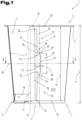
- central refers to the actuating means 25 as half its dimension in the direction of the overall height 21 or the longitudinal axis 8.
- the two separating sections 23, 24 are provided on both sides of the actuating means 25 and each extend in the direction of the respective end face 19, 20.
- the actuating means 25 in turn defines a detection section 27 with a first detection section end 28 and a second detection section end 29 spaced apart from one another in the direction of the construction height 21.
- the two detection section ends 28, 29 are thus arranged or end at a distance 30 from one another in the direction of the construction height 21 of the casing. It can also be seen that the detection section 27 of the actuating means 25 is arranged or designed outside the overlap region 16.
- the offset 31 can have a value which is selected from a value range with a lower limit of 1.0 mm and an upper limit of 10.0 mm.
- the value range can preferably have a lower limit of 2.0 mm and an upper limit of 6.0 mm.
- the first separating section 23 in turn has a first end 32 facing the actuating means 25, the second separating section 24 having a second end 33 facing the actuating means 25.
- the area of the imaginary connecting line 26 between the The casing is designed to be uninterrupted at both ends 32, 33 due to the intended lateral offset 31 of the actuating means 25.
- the arrangement of the two ends 32, 33 of the separating sections 23, 24, which are spaced apart from one another in the direction of the construction height 21, with respect to the detection section 27 forming the actuating means 25 is selected such that the first detection section end 28 of the detection section 27 overlaps the adjacent first end 32 of the first separating section 23 on the side facing away from the second separating section 24.
- a first intended separating section 34 is formed in the casing of the outer part 12 between the first detection section end 28 and the first end 32 of the first separating section 23, as seen in the circumferential direction.
- the second detection section end 29 of the detection section 27 overlaps the adjacent second end 33 of the second separating section 24 on the side facing away from the first separating section 23.
- a second intended separating section 35 is also formed in the casing of the outer part 12 between the second detection section end 29 and the second end 33 of the second separating section 24, viewed in the circumferential direction.
- the two intended separating sections 34, 35 are formed by the reduced dimensions of the casing material between the respective detection section end 28 or 29 and the respective end 32 or 33.
- the two ends 32 and 33 of the separating sections 23, 24 are arranged closer to one another than the two detection section ends 28 and 29, which are spaced apart by the distance 30.
- Each of the two separating sections 23, 24 comprises a plurality of predetermined separating points arranged one behind the other in a row, which are usually designed as perforations, in particular also as short cuts, in the material of the outer part 12.
- first predetermined separation points 36 those predetermined separation points which are arranged directly adjacent to the respective detection section ends 28, 29 are referred to as first predetermined separation points 36.
- second predetermined separation points 37 and third predetermined separation points 38 are further predetermined separation points provided subsequently in the direction of one of the two end faces 19, 20.
- the predetermined separation points 36, 37, 38 are aligned with respect to a plane 39 which is centrally and in normal alignment with the longitudinal axis 8 - see Fig. 1 - designed and arranged in mirror image to one another. Therefore, only those predetermined separation points 36, 37, 38 located in the area of the first separation section 23 are described in more detail and are to be transferred in an analogous manner to the second separation section 24.
- the first predetermined separation point 36 has, on its side facing away from the detection section 27, a first longitudinal profile 40 which runs essentially in a parallel direction with respect to the imaginary connecting line 26 between the two separation sections 23, 24 or in a parallel direction with respect to one of the longitudinal edges 17, 18.
- first longitudinal profile 40 which runs essentially in a parallel direction with respect to the imaginary connecting line 26 between the two separation sections 23, 24 or in a parallel direction with respect to one of the longitudinal edges 17, 18.
- Adjoining the first longitudinal profile 40 is a second longitudinal profile 41 which is located on the side facing the detection section 27 and is aligned so as to protrude in the direction of the detection section 27. Due to the approximately parallel alignment of the first longitudinal profile 40, it is designed to run in a straight line.
- the first longitudinal profile 40 and the second longitudinal profile 41 together form the first predetermined separation point 36 and are formed, for example, by a punching process and preferably completely penetrate the thickness of the blank 13 to form the outer part 12.
- the second longitudinal profile 41 of the first predetermined separation point 36 can be curved in an arc shape. However, an angular and straight design of the second longitudinal profile 41 of the first predetermined separation point 36 in the direction of the actuating means 25 would also be possible. In any case, the second longitudinal profile 41 of the first predetermined separation point 36 ends before reaching the detection section 27.
- the second and/or third intended separation points 37, 38 of the two separation sections 23, 24 located downstream of the first intended separation points 36 can have an orientation that runs at an angle to the imaginary connecting line 26.
- the angular orientation of the second intended separation points 37 and/or the third intended separation points 38 of the first separation section 23 and the second separation section 24 can be selected such that they are each aligned converging towards each other on the side facing away from the actuating means 25.
- the intended separation points 37, 38 are to be considered as being symmetrical with respect to the normal plane - plane 39.
- the second intended separation points 37 can preferably be longer than the subsequent third intended separation points 38.
- an angle 42-1, 42-2 enclosed by the second and/or third predetermined separation points 37 38 of the first separation section 23 and by the second and/or third predetermined separation points 37, 38 of the second separation section 24 to be designed differently from one another, starting from the actuating means 25 towards the respective end faces 19, 20.
- the angle 42-1 between the second predetermined separation points 37 or the angle 42-2 between the corresponding third predetermined separation points 38 must always be considered.
- the enclosed angle 42-1, 42-2 can be designed to increase and thus be larger, starting from the actuating means 25 towards the respective end faces 19, 20.
- the enclosed angle 42-2 between the respective third predetermined separation points 38 is always chosen to be the same, but larger than the angle 42-1 enclosed by the second predetermined separation points 37.
- the design of the actuating means 25 and its detection section 27 can be selected in different ways.
- the detection section 27 is formed by a cutting line that completely penetrates the casing.
- the cutting line here has a straight longitudinal course. Further design options for the intended separation area 22, in particular for its actuating means 25, are explained in more detail in the following figures.
- the overlapping area 16 between the two end sections 14, 15 can be selected such that the intended separation area 22 is arranged or formed in the first end section 14 and the first end section 14 is overlapped on the inside in the overlapping area 16 and on the outside by the second end section 15.
- the intended separation area 22 is arranged in a parallel direction with respect to the second longitudinal edge 18 of the overlapping outer second end section 15.
- the intended separation region 22 is arranged or formed outside the overlap region 16.
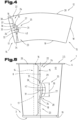
- FIG. 4 a further and possibly independent embodiment of the blank 13 for forming the outer part 12 is shown, whereby again the same reference numerals or component designations are used for the same parts as in the previous Fig. 1 to 3 To avoid unnecessary repetition, please refer to the detailed description in the previous Fig. 1 to 3 pointed out or referred to.
- the basic structure and arrangement of the predetermined separation area 22 is chosen in the same way as has already been described in detail above. Therefore, only the existing differences will be discussed in more detail.
- the intended separation area 22 of the blank 13 comprises the two separation sections 23 and 24 as well as the detection section 27 located between them.
- the actuating means 25 further comprises, in addition to the detection section 27, an opening 43 that completely penetrates the casing.
- the opening 43 is arranged on the side of the detection section 27 facing away from the overlapping area 16 and immediately adjacent to the detection section 27. Furthermore, the opening 43 ends at the cutting line of the detection section 27. By providing the opening, the detection section 27 can be made easier for a user to grasp.
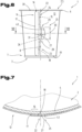
- FIG. 5 a further and possibly independent embodiment of the blank 13 for forming the outer part 12 is shown, whereby again the same reference numerals or component designations are used for the same parts as in the previous Fig. 1 to 4 To avoid unnecessary repetition, please refer to the detailed description in the previous Fig. 1 to 4 pointed out or referred to.
- the intended separation area 22 of the blank 13 comprises the two separation sections 23 and 24 as well as the detection section 27 located between them.
- the cutting line for forming the detection section 27 has a curved longitudinal profile.
- the longitudinal profile is curved in an arc shape.
- the detection section 27 has a convex longitudinal profile with a curvature facing away from the overlap region 16. This allows a type of actuating tab to be formed, which can make it even easier to grasp and actuate the separation process.
- a concave curvature could also be provided for the formation of the cutting line.
- an opening 43 in the casing can be provided to form the actuating means 25.
- the formation of the intended separation sections 34, 35 and their intended separation points 36, 37 and 38 can be carried out analogously to what has already been described above.
- FIG. 6 and 7 a further and possibly independent embodiment of the blank 13 for forming the outer part 12 is shown, whereby again the same reference numerals or component designations are used for the same parts as in the previous Fig. 1 to 5 To avoid unnecessary repetition, please refer to the detailed description in the previous Fig. 1 to 5 pointed out or referred to.
- the design and arrangement of the intended separation area 22 in the first end section 14 of the blank 13 can be carried out according to an embodiment already described above.
- the intended separation area 22 in turn comprises the two separation sections 23 and 24 located on both sides of the actuating means 25.
- the first end section 14 with the intended separation region 22 located therein is overlapped by the second end section 15 in the overlap region 16
- the first end section 14 is arranged on the outside in the overlap region 16 and thus overlaps the second end section 15.
- the predetermined separation region 22 is thus also arranged or formed in the first end section 14, wherein the second end section 15 is arranged on the inside in the overlap region 16 and thus overlaps.
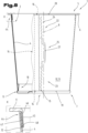
- FIG. 8 The combination packaging container 1 with the inner container 2 and the outer part 12 surrounding the container casing 4 is shown partially in section.
- the basic structure of the inner container 2 and the outer part 12 corresponds to that previously described in the Fig. 1 to 7 Therefore, for equal parts, the same Reference symbols or component designations as in the previous Fig. 1 to 7 To avoid unnecessary repetition, please refer to the detailed description in the previous Fig. 1 to 7
- the previously described separation area 22 with its actuating means 25 and the separation sections 23, 24 on both sides is designed analogously to the previous Fig. 1 to 7 For the sake of clarity, many of the additional reference symbols previously used have been omitted.
- a holding arrangement 44 is provided immediately adjacent to the flange 6 in order to be able to additionally hold the outer part 12 on the inner container 2, in particular to be able to hold it in a form-fitting manner.
- the section of the holding arrangement 44 is shown in detail "X" on the left below the combination packaging container 1 on an enlarged scale.
- the sleeve-shaped outer part 12 has its own folded edge 45.
- the folded edge 45 is folded inwards in the direction of the longitudinal axis 8 or in the direction of the container casing (4), whereby no additional disturbing edges are arranged or formed on the outside of the sleeve-shaped outer part 12 facing the viewer.
- the folded edge 45 can be provided or formed over the entire circumference or almost over the entire circumference of the outer part 12.
- the container casing 4 has an inwardly offset wall section 46 which forms a receiving space 47 for the folded edge 45.
- the receiving space 47 is preferably designed to be continuous over the entire circumference, but can also be designed only in segments or sections.
- a step surface 48 is provided, starting from the inwardly offset wall section 46, which projects onto the side facing away from the longitudinal axis 8.
- the inwardly folded folded edge 45 is supported with its front edge on the step surface 48.
- the folded edge 45 together with the outer part 12 is pushed in the direction of the flange 6 until the folded edge 45 snaps completely into the receiving space 47 provided for it in the area of the open end 5 of the inner container 2. This allows an additional mechanical locking of the sleeve-shaped outer part 12 to be achieved on the inner container 2.
- the folded edge 45 is preferably placed continuously against the casing or the wall of the sleeve-shaped outer part 12 during the flanging process.
- the holding arrangement 44 between the outer part 12 and the inner container 2 could also be formed by at least one holding lug protruding from the container casing 4 on the side facing away from the longitudinal axis 8 and a recess or holding opening arranged or formed in the outer part 12.
- the holding lug protrudes into the recess or the holding opening and thus holds the outer part 12 on the inner container 2.
- the outer part 12 has generally been additionally secured against accidental separation with an adhesive at at least one adhesive point or an adhesive point on the container casing 4 of the inner container 2 if the support of the outer part 12 on the bottom shoulder 11 is no longer sufficient due to excessive dimensional differences.
- the outer part 12 When separating waste, the outer part 12 must first be separated in the intended separation area 22 formed therein, then the adhesive point must be removed and only then can the sorted, separate disposal be carried out.
- the additional adhesive may be provided, but is not included in the Fig. 9 described embodiment is not absolutely necessary and can be omitted entirely.
- FIG. 9 A possibility for carrying out the separation of the intended separation area 22 is shown in a simplified manner according to the different embodiments described above.
- the combination packaging container 1 is shown in its undeformed original form.
- the outer part 12 After removing the goods contained in the combination packaging container 1, usually a foodstuff or a consumable, the outer part 12 must be detached from the inner container 2 for proper and sorted disposal.
- the material of the outer part 12 is cellulose (cardboard, strong paper or the like) and that of the inner container 2 is a plastic material.
- a compressive force -F- in the direction of the combination packaging container 1 and in the process to carry out a desired spatial deformation of at least the container casing 4.
- the compressive force -F- is preferably exerted in the direction of the longitudinal axis 8 or in an angular force orientation to this. In this case, the entire combination packaging container 1 is spatially deformed.
- the applied compressive force -F- is at least partially converted by the deformation of the combination packaging container 1 into a separation force that separates the intended separation area 22 along the intended separation points 36 and 37, the intended separation sections 34 and 35 and the separation sections 23 and 24.
- the application of the pressure force -F- saves the search for the desired separation area 22, the detection of the actuating means 25 and the subsequent separation process.
- the simplest way, according to the process proposed here, is to place the combination packaging container 1 intended for separation either with its closed end 7 or its open end 5 of the inner container 2 on a support surface formed, for example, by a solid base and then the person exerts the pressure force -F- on the end facing away from the support surface in the direction of the support surface.
- the support surface or the solid base can be, for example, the floor, the table or a worktop.
- the pressure force -F- can be applied directly by the person with his or her hand(s) or with his or her foot.
- a marking or an indication of how the separation process is to be carried out can be attached or arranged, for example, on the base 3 of the inner container 2 and/or on the outer part 12.
- the marking on the base 3 can be applied or arranged, for example, in the area of the longitudinal axis 8 and/or on the outer circumference on the base side.
- a separate pressure device designed for this purpose could also be provided, into which the combination packaging container 1 to be separated is introduced and then the Pressure force -F- is applied mechanically.
- the separation of the intended separation area 22 it would also be possible for the separation of the intended separation area 22 to take place during the waste disposal by a pressing device or the like and for the pressure force -F- to be applied by this. This usually takes place when the transport volume is reduced.
- the separation process of the intended separation area 22 is carried out mechanically by a press or a squeezing device during collection and/or waste disposal.
Landscapes
- Engineering & Computer Science (AREA)
- Mechanical Engineering (AREA)
- Ceramic Engineering (AREA)
- Packages (AREA)
- Cartons (AREA)
- Making Paper Articles (AREA)
Priority Applications (1)
| Application Number | Priority Date | Filing Date | Title |
|---|---|---|---|
| RS20250325A RS66637B1 (sr) | 2019-06-07 | 2020-06-03 | Spoljni deo u obliku manžente i kombinovani kontejner za pakovanje opremljen njime i postupak odvajanja kombinovanog kontejnera za pakovanje |
Applications Claiming Priority (3)
| Application Number | Priority Date | Filing Date | Title |
|---|---|---|---|
| ATA50520/2019A AT522907B1 (de) | 2019-06-07 | 2019-06-07 | Manschettenförmiges Außenteil sowie damit ausgestatteter Kombi-Verpackungsbehälter |
| EP20731421.2A EP3980340B1 (de) | 2019-06-07 | 2020-06-03 | Manschettenförmiges aussenteil sowie damit ausgestatteter kombi-verpackungsbehälter und verfahren zum trennen des kombi-verpackungsbehälters |
| PCT/EP2020/065278 WO2020245148A1 (de) | 2019-06-07 | 2020-06-03 | Manschettenförmiges aussenteil sowie damit ausgestatteter kombi-verpackungsbehälter und verfahren zum trennen des kombi-verpackungsbehälters |
Related Parent Applications (1)
| Application Number | Title | Priority Date | Filing Date |
|---|---|---|---|
| EP20731421.2A Division EP3980340B1 (de) | 2019-06-07 | 2020-06-03 | Manschettenförmiges aussenteil sowie damit ausgestatteter kombi-verpackungsbehälter und verfahren zum trennen des kombi-verpackungsbehälters |
Publications (4)
| Publication Number | Publication Date |
|---|---|
| EP4265536A2 EP4265536A2 (de) | 2023-10-25 |
| EP4265536A3 EP4265536A3 (de) | 2024-01-24 |
| EP4265536B1 true EP4265536B1 (de) | 2025-02-26 |
| EP4265536C0 EP4265536C0 (de) | 2025-02-26 |
Family
ID=71069821
Family Applications (2)
| Application Number | Title | Priority Date | Filing Date |
|---|---|---|---|
| EP23195056.9A Active EP4265536B1 (de) | 2019-06-07 | 2020-06-03 | Manschettenförmiges aussenteil sowie damit ausgestatteter kombi-verpackungsbehälter und verfahren zum trennen des kombi-verpackungsbehälters |
| EP20731421.2A Active EP3980340B1 (de) | 2019-06-07 | 2020-06-03 | Manschettenförmiges aussenteil sowie damit ausgestatteter kombi-verpackungsbehälter und verfahren zum trennen des kombi-verpackungsbehälters |
Family Applications After (1)
| Application Number | Title | Priority Date | Filing Date |
|---|---|---|---|
| EP20731421.2A Active EP3980340B1 (de) | 2019-06-07 | 2020-06-03 | Manschettenförmiges aussenteil sowie damit ausgestatteter kombi-verpackungsbehälter und verfahren zum trennen des kombi-verpackungsbehälters |
Country Status (7)
| Country | Link |
|---|---|
| US (1) | US11731799B2 (sr) |
| EP (2) | EP4265536B1 (sr) |
| AT (1) | AT522907B1 (sr) |
| HU (2) | HUE064317T2 (sr) |
| PL (2) | PL4265536T3 (sr) |
| RS (2) | RS66637B1 (sr) |
| WO (1) | WO2020245148A1 (sr) |
Families Citing this family (11)
| Publication number | Priority date | Publication date | Assignee | Title |
|---|---|---|---|---|
| AT522907B1 (de) | 2019-06-07 | 2021-04-15 | Greiner Packaging Ag | Manschettenförmiges Außenteil sowie damit ausgestatteter Kombi-Verpackungsbehälter |
| AT524230B1 (de) | 2021-02-25 | 2022-04-15 | Greiner Packaging Ag | Manschettenförmiges Außenteil, damit ausgestatteter Kombi-Verpackungsbehälter und Verfahren zum Trennen des Kombi-Verpackungsbehälters |
| HUE072442T2 (hu) | 2021-02-25 | 2025-11-28 | Greiner Packaging Ag | Mandzsettaalakú külsõ rész, valamint ezzel ellátott kombinált csomagolótartály és eljárás a kombinált csomagolótartály szétválasztására |
| CN117693475A (zh) * | 2021-03-23 | 2024-03-12 | 麦克拉伦包装有限公司 | 包装 |
| EP4212443A1 (en) | 2022-01-18 | 2023-07-19 | PACCOR Packaging GmbH | Blank for a packaging shell of a cup packaging, cup packaging having a packaging shell, and method for separating the cup packaging and the packaging shell |
| AT526366B1 (de) | 2022-06-08 | 2024-09-15 | Greiner Packaging Ag | Zuschnitt, sowie aus einem Zuschnitt gebildetes manschettenförmiges Außenteil zum Ummanteln eines becherförmigen Innenbehälters, sowie Kombi-Verpackungsbehälter |
| AT525891B1 (de) * | 2022-10-10 | 2023-09-15 | Greiner Packaging Ag | Außenteil und damit ausgestatteter Kombi-Verpackungsbehälter, Verfahren zur Herstellung und |
| AT525879B1 (de) | 2022-10-10 | 2023-09-15 | Greiner Packaging Int Gmbh | Mehrweg-Kunststoffbehälter und Verfahren zur Wiederaufbereitung |
| DE202022107170U1 (de) * | 2022-12-22 | 2024-03-27 | Optipack Gmbh | Kombi-Verpackungsbehälter |
| EP4393832A1 (en) | 2023-01-02 | 2024-07-03 | PACCOR Packaging GmbH | Blank for a packaging shell of a cup packaging, method for producing a blank, cup packaging having a packaging shell, and method for separating the cup packaging and the packaging shell |
| AT526840B1 (de) | 2023-09-14 | 2024-08-15 | Greiner Packaging Ag | Kombi-Verpackungsbehälter mit einem Behälter und einem Außenteil |
Citations (12)
| Publication number | Priority date | Publication date | Assignee | Title |
|---|---|---|---|---|
| EP0408515B1 (de) | 1989-07-14 | 1993-09-22 | Sandherr Packungen AG | Verpackungsbehälter |
| JPH1086971A (ja) | 1996-09-11 | 1998-04-07 | Toppan Printing Co Ltd | 易分離性複合容器 |
| JPH11278456A (ja) | 1998-03-28 | 1999-10-12 | Nippon Matai Co Ltd | 二重カップ |
| AT500137A1 (de) | 2004-05-12 | 2005-11-15 | Rundpack Ag | Verpackungsbehälter für lebensmittel |
| JP2007238149A (ja) | 2006-03-09 | 2007-09-20 | Tokan Kogyo Co Ltd | 二重容器 |
| DE202007013419U1 (de) | 2007-09-20 | 2007-12-06 | VICTOR Güthoff & Leonhardt GmbH | Reißbare Kunststoff-Folie, insbesondere für Verpackungszwecke |
| JP2009012536A (ja) | 2007-07-02 | 2009-01-22 | Mazda Motor Corp | 車両の乗員保護装置 |
| WO2009130043A1 (de) | 2008-04-24 | 2009-10-29 | Rundpack Ag | Verfahren zur herstellung eines kombi-verpackungsbehälters sowie eines mantelförmigen aussenteils |
| JP2010126209A (ja) | 2008-11-28 | 2010-06-10 | Toppan Printing Co Ltd | 開封機能付き紙容器 |
| AT508841A1 (de) | 2009-09-24 | 2011-04-15 | Rundpack Ag | Verpackungseinheit, insbesondere für nahrungsmittel |
| EP2338804A1 (de) | 2009-12-23 | 2011-06-29 | Optipack GmbH | Verpackungsbehälter |
| JP2019135167A (ja) | 2018-02-05 | 2019-08-15 | 日本トーカンパッケージ株式会社 | 収納ケース |
Family Cites Families (6)
| Publication number | Priority date | Publication date | Assignee | Title |
|---|---|---|---|---|
| US3827620A (en) * | 1972-11-17 | 1974-08-06 | R Ludder | Non-reusable nestable cup or container |
| US5007578A (en) * | 1990-08-06 | 1991-04-16 | Simone Ronald A | Wrap-around body with promotional flap extension |
| DE29714534U1 (de) * | 1997-08-14 | 1998-12-17 | Gizeh Verpackungen GmbH & Co. KG, 51702 Bergneustadt | Becher |
| JP5401780B2 (ja) | 2007-11-21 | 2014-01-29 | 凸版印刷株式会社 | 隠蔽情報付き容器 |
| DE102011014844A1 (de) * | 2011-03-23 | 2012-09-27 | Optipack Gmbh | Behälter mit Banderole |
| AT522907B1 (de) | 2019-06-07 | 2021-04-15 | Greiner Packaging Ag | Manschettenförmiges Außenteil sowie damit ausgestatteter Kombi-Verpackungsbehälter |
-
2019
- 2019-06-07 AT ATA50520/2019A patent/AT522907B1/de active
-
2020
- 2020-06-03 EP EP23195056.9A patent/EP4265536B1/de active Active
- 2020-06-03 PL PL23195056.9T patent/PL4265536T3/pl unknown
- 2020-06-03 HU HUE20731421A patent/HUE064317T2/hu unknown
- 2020-06-03 PL PL20731421.2T patent/PL3980340T3/pl unknown
- 2020-06-03 EP EP20731421.2A patent/EP3980340B1/de active Active
- 2020-06-03 HU HUE23195056A patent/HUE071469T2/hu unknown
- 2020-06-03 US US17/614,631 patent/US11731799B2/en active Active
- 2020-06-03 RS RS20250325A patent/RS66637B1/sr unknown
- 2020-06-03 WO PCT/EP2020/065278 patent/WO2020245148A1/de not_active Ceased
- 2020-06-03 RS RS20231146A patent/RS64902B1/sr unknown
Patent Citations (12)
| Publication number | Priority date | Publication date | Assignee | Title |
|---|---|---|---|---|
| EP0408515B1 (de) | 1989-07-14 | 1993-09-22 | Sandherr Packungen AG | Verpackungsbehälter |
| JPH1086971A (ja) | 1996-09-11 | 1998-04-07 | Toppan Printing Co Ltd | 易分離性複合容器 |
| JPH11278456A (ja) | 1998-03-28 | 1999-10-12 | Nippon Matai Co Ltd | 二重カップ |
| AT500137A1 (de) | 2004-05-12 | 2005-11-15 | Rundpack Ag | Verpackungsbehälter für lebensmittel |
| JP2007238149A (ja) | 2006-03-09 | 2007-09-20 | Tokan Kogyo Co Ltd | 二重容器 |
| JP2009012536A (ja) | 2007-07-02 | 2009-01-22 | Mazda Motor Corp | 車両の乗員保護装置 |
| DE202007013419U1 (de) | 2007-09-20 | 2007-12-06 | VICTOR Güthoff & Leonhardt GmbH | Reißbare Kunststoff-Folie, insbesondere für Verpackungszwecke |
| WO2009130043A1 (de) | 2008-04-24 | 2009-10-29 | Rundpack Ag | Verfahren zur herstellung eines kombi-verpackungsbehälters sowie eines mantelförmigen aussenteils |
| JP2010126209A (ja) | 2008-11-28 | 2010-06-10 | Toppan Printing Co Ltd | 開封機能付き紙容器 |
| AT508841A1 (de) | 2009-09-24 | 2011-04-15 | Rundpack Ag | Verpackungseinheit, insbesondere für nahrungsmittel |
| EP2338804A1 (de) | 2009-12-23 | 2011-06-29 | Optipack GmbH | Verpackungsbehälter |
| JP2019135167A (ja) | 2018-02-05 | 2019-08-15 | 日本トーカンパッケージ株式会社 | 収納ケース |
Also Published As
| Publication number | Publication date |
|---|---|
| US20220227524A1 (en) | 2022-07-21 |
| AT522907B1 (de) | 2021-04-15 |
| HUE064317T2 (hu) | 2024-03-28 |
| WO2020245148A1 (de) | 2020-12-10 |
| EP3980340A1 (de) | 2022-04-13 |
| EP4265536A2 (de) | 2023-10-25 |
| EP3980340C0 (de) | 2023-09-06 |
| HUE071469T2 (hu) | 2025-08-28 |
| RS66637B1 (sr) | 2025-04-30 |
| RS64902B1 (sr) | 2023-12-29 |
| PL3980340T3 (pl) | 2024-03-04 |
| AT522907A1 (de) | 2021-03-15 |
| EP4265536A3 (de) | 2024-01-24 |
| CA3142212A1 (en) | 2020-12-10 |
| US11731799B2 (en) | 2023-08-22 |
| EP3980340B1 (de) | 2023-09-06 |
| PL4265536T3 (pl) | 2025-07-28 |
| EP4265536C0 (de) | 2025-02-26 |
Similar Documents
| Publication | Publication Date | Title |
|---|---|---|
| EP4265536B1 (de) | Manschettenförmiges aussenteil sowie damit ausgestatteter kombi-verpackungsbehälter und verfahren zum trennen des kombi-verpackungsbehälters | |
| EP4298025B1 (de) | Manschettenförmiges aussenteil, damit ausgestatteter kombi-verpackungsbehälter und verfahren zum trennen des kombi-verpackungsbehälters | |
| DE102004032100B4 (de) | Verfahren zum Ablösen bzw. Abtrennen einer auf den Rand des Halses einer Flasche od. dergl. aufgesiegelten Siegelfolie und Schraubkappen zur Ausführung dieser Verfahren | |
| EP1747151B1 (de) | Manipulationssicherer deckel | |
| EP2125542B1 (de) | Verschliessvorrichtung aus kunststoff mit schneidhülse | |
| AT508081B1 (de) | Kombi-verpackungsbehälter sowie verfahren zu dessen herstellung | |
| WO2009130043A1 (de) | Verfahren zur herstellung eines kombi-verpackungsbehälters sowie eines mantelförmigen aussenteils | |
| EP4298024B1 (de) | Manschettenförmiges aussenteil, damit ausgestatteter kombi-verpackungsbehälter und verfahren zum trennen des kombi-verpackungsbehälters | |
| DE4411925A1 (de) | Verfahren zum Abdecken einer Schnittkante einer Öffnung eines Behälters mit einem Schutzbezug | |
| AT513804B1 (de) | Verfahren zur Herstellung eines Kombi-Verpackungsbehälters sowie Kombi-Verpackungsbehälter | |
| EP3107817B1 (de) | Verschlussdeckel mit originalitätssicherung sowie damit versehene verpackungseinheit | |
| EP2100818A1 (de) | Aufreissbare Siegelverpackung | |
| AT526366B1 (de) | Zuschnitt, sowie aus einem Zuschnitt gebildetes manschettenförmiges Außenteil zum Ummanteln eines becherförmigen Innenbehälters, sowie Kombi-Verpackungsbehälter | |
| AT525891B1 (de) | Außenteil und damit ausgestatteter Kombi-Verpackungsbehälter, Verfahren zur Herstellung und | |
| EP3730418B1 (de) | Behälter | |
| AT506749A1 (de) | Verfahren zur herstellung eines kombi-verpackungsbehälters | |
| EP0921985B1 (de) | Verfahren zur herstellung eines befüllten behälters | |
| EP4389625A1 (de) | Kombi-verpackungsbehälter | |
| EP1753665B1 (de) | Kartonverbunddose | |
| EP4534432A1 (de) | Zuschnitt, aussenteil, kombi-verpackungsbehälter mit einem behälter und einem aussenteil, verfahren zur herstellung eines kombi-verpackungsbehälters, verfahren zum öffnen eines kombi-verpackungsbehälters | |
| AT507739A1 (de) | Verfahren zur herstellung eines kombi - verpackungsbehälters |
Legal Events
| Date | Code | Title | Description |
|---|---|---|---|
| PUAI | Public reference made under article 153(3) epc to a published international application that has entered the european phase |
Free format text: ORIGINAL CODE: 0009012 |
|
| STAA | Information on the status of an ep patent application or granted ep patent |
Free format text: STATUS: THE APPLICATION HAS BEEN PUBLISHED |
|
| AC | Divisional application: reference to earlier application |
Ref document number: 3980340 Country of ref document: EP Kind code of ref document: P |
|
| AK | Designated contracting states |
Kind code of ref document: A2 Designated state(s): AL AT BE BG CH CY CZ DE DK EE ES FI FR GB GR HR HU IE IS IT LI LT LU LV MC MK MT NL NO PL PT RO RS SE SI SK SM TR |
|
| REG | Reference to a national code |
Ref country code: DE Ref legal event code: R079 Free format text: PREVIOUS MAIN CLASS: B65D0025360000 Ipc: B65D0001260000 Ref document number: 502020010509 Country of ref document: DE |
|
| PUAL | Search report despatched |
Free format text: ORIGINAL CODE: 0009013 |
|
| AK | Designated contracting states |
Kind code of ref document: A3 Designated state(s): AL AT BE BG CH CY CZ DE DK EE ES FI FR GB GR HR HU IE IS IT LI LT LU LV MC MK MT NL NO PL PT RO RS SE SI SK SM TR |
|
| RIC1 | Information provided on ipc code assigned before grant |
Ipc: B65D 25/36 20060101ALI20231221BHEP Ipc: B65D 1/26 20060101AFI20231221BHEP |
|
| STAA | Information on the status of an ep patent application or granted ep patent |
Free format text: STATUS: REQUEST FOR EXAMINATION WAS MADE |
|
| 17P | Request for examination filed |
Effective date: 20240312 |
|
| RBV | Designated contracting states (corrected) |
Designated state(s): AL AT BE BG CH CY CZ DE DK EE ES FI FR GB GR HR HU IE IS IT LI LT LU LV MC MK MT NL NO PL PT RO RS SE SI SK SM TR |
|
| GRAP | Despatch of communication of intention to grant a patent |
Free format text: ORIGINAL CODE: EPIDOSNIGR1 |
|
| STAA | Information on the status of an ep patent application or granted ep patent |
Free format text: STATUS: GRANT OF PATENT IS INTENDED |
|
| INTG | Intention to grant announced |
Effective date: 20240422 |
|
| TPAC | Observations filed by third parties |
Free format text: ORIGINAL CODE: EPIDOSNTIPA |
|
| GRAJ | Information related to disapproval of communication of intention to grant by the applicant or resumption of examination proceedings by the epo deleted |
Free format text: ORIGINAL CODE: EPIDOSDIGR1 |
|
| STAA | Information on the status of an ep patent application or granted ep patent |
Free format text: STATUS: REQUEST FOR EXAMINATION WAS MADE |
|
| INTC | Intention to grant announced (deleted) | ||
| GRAP | Despatch of communication of intention to grant a patent |
Free format text: ORIGINAL CODE: EPIDOSNIGR1 |
|
| STAA | Information on the status of an ep patent application or granted ep patent |
Free format text: STATUS: GRANT OF PATENT IS INTENDED |
|
| INTG | Intention to grant announced |
Effective date: 20241004 |
|
| GRAS | Grant fee paid |
Free format text: ORIGINAL CODE: EPIDOSNIGR3 |
|
| GRAA | (expected) grant |
Free format text: ORIGINAL CODE: 0009210 |
|
| STAA | Information on the status of an ep patent application or granted ep patent |
Free format text: STATUS: THE PATENT HAS BEEN GRANTED |
|
| AC | Divisional application: reference to earlier application |
Ref document number: 3980340 Country of ref document: EP Kind code of ref document: P |
|
| AK | Designated contracting states |
Kind code of ref document: B1 Designated state(s): AL AT BE BG CH CY CZ DE DK EE ES FI FR GB GR HR HU IE IS IT LI LT LU LV MC MK MT NL NO PL PT RO RS SE SI SK SM TR |
|
| REG | Reference to a national code |
Ref country code: GB Ref legal event code: FG4D Free format text: NOT ENGLISH |
|
| REG | Reference to a national code |
Ref country code: CH Ref legal event code: EP |
|
| REG | Reference to a national code |
Ref country code: DE Ref legal event code: R096 Ref document number: 502020010509 Country of ref document: DE |
|
| REG | Reference to a national code |
Ref country code: IE Ref legal event code: FG4D Free format text: LANGUAGE OF EP DOCUMENT: GERMAN |
|
| U01 | Request for unitary effect filed |
Effective date: 20250324 |
|
| U07 | Unitary effect registered |
Designated state(s): AT BE BG DE DK EE FI FR IT LT LU LV MT NL PT RO SE SI Effective date: 20250328 |
|
| PG25 | Lapsed in a contracting state [announced via postgrant information from national office to epo] |
Ref country code: ES Free format text: LAPSE BECAUSE OF FAILURE TO SUBMIT A TRANSLATION OF THE DESCRIPTION OR TO PAY THE FEE WITHIN THE PRESCRIBED TIME-LIMIT Effective date: 20250226 |
|
| PGFP | Annual fee paid to national office [announced via postgrant information from national office to epo] |
Ref country code: GB Payment date: 20250627 Year of fee payment: 6 |
|
| PG25 | Lapsed in a contracting state [announced via postgrant information from national office to epo] |
Ref country code: IS Free format text: LAPSE BECAUSE OF FAILURE TO SUBMIT A TRANSLATION OF THE DESCRIPTION OR TO PAY THE FEE WITHIN THE PRESCRIBED TIME-LIMIT Effective date: 20250626 |
|
| PGFP | Annual fee paid to national office [announced via postgrant information from national office to epo] |
Ref country code: RS Payment date: 20250516 Year of fee payment: 6 |
|
| PG25 | Lapsed in a contracting state [announced via postgrant information from national office to epo] |
Ref country code: HR Free format text: LAPSE BECAUSE OF FAILURE TO SUBMIT A TRANSLATION OF THE DESCRIPTION OR TO PAY THE FEE WITHIN THE PRESCRIBED TIME-LIMIT Effective date: 20250226 |
|
| U20 | Renewal fee for the european patent with unitary effect paid |
Year of fee payment: 6 Effective date: 20250612 |
|
| PG25 | Lapsed in a contracting state [announced via postgrant information from national office to epo] |
Ref country code: GR Free format text: LAPSE BECAUSE OF FAILURE TO SUBMIT A TRANSLATION OF THE DESCRIPTION OR TO PAY THE FEE WITHIN THE PRESCRIBED TIME-LIMIT Effective date: 20250527 |
|
| PGFP | Annual fee paid to national office [announced via postgrant information from national office to epo] |
Ref country code: TR Payment date: 20250526 Year of fee payment: 6 |
|
| PGFP | Annual fee paid to national office [announced via postgrant information from national office to epo] |
Ref country code: CZ Payment date: 20250514 Year of fee payment: 6 |
|
| PGFP | Annual fee paid to national office [announced via postgrant information from national office to epo] |
Ref country code: IE Payment date: 20250627 Year of fee payment: 6 |
|
| PGFP | Annual fee paid to national office [announced via postgrant information from national office to epo] |
Ref country code: HU Payment date: 20250506 Year of fee payment: 6 |
|
| REG | Reference to a national code |
Ref country code: HU Ref legal event code: AG4A Ref document number: E071469 Country of ref document: HU |
|
| PG25 | Lapsed in a contracting state [announced via postgrant information from national office to epo] |
Ref country code: SM Free format text: LAPSE BECAUSE OF FAILURE TO SUBMIT A TRANSLATION OF THE DESCRIPTION OR TO PAY THE FEE WITHIN THE PRESCRIBED TIME-LIMIT Effective date: 20250226 |
|
| PGFP | Annual fee paid to national office [announced via postgrant information from national office to epo] |
Ref country code: NO Payment date: 20250630 Year of fee payment: 6 |
|
| PGFP | Annual fee paid to national office [announced via postgrant information from national office to epo] |
Ref country code: PL Payment date: 20250408 Year of fee payment: 6 |
|
| PGFP | Annual fee paid to national office [announced via postgrant information from national office to epo] |
Ref country code: CH Payment date: 20250717 Year of fee payment: 6 |
|
| PG25 | Lapsed in a contracting state [announced via postgrant information from national office to epo] |
Ref country code: SK Free format text: LAPSE BECAUSE OF FAILURE TO SUBMIT A TRANSLATION OF THE DESCRIPTION OR TO PAY THE FEE WITHIN THE PRESCRIBED TIME-LIMIT Effective date: 20250226 |
|
| PLBI | Opposition filed |
Free format text: ORIGINAL CODE: 0009260 |
|
| PLAX | Notice of opposition and request to file observation + time limit sent |
Free format text: ORIGINAL CODE: EPIDOSNOBS2 |
|
| 26 | Opposition filed |
Opponent name: FAERCH A/S Effective date: 20251125 |
|
| PG25 | Lapsed in a contracting state [announced via postgrant information from national office to epo] |
Ref country code: MC Free format text: LAPSE BECAUSE OF FAILURE TO SUBMIT A TRANSLATION OF THE DESCRIPTION OR TO PAY THE FEE WITHIN THE PRESCRIBED TIME-LIMIT Effective date: 20250226 |
|
| PLBB | Reply of patent proprietor to notice(s) of opposition received |
Free format text: ORIGINAL CODE: EPIDOSNOBS3 |