EP4265540A1 - Système de contrôle de pression pour maintenir une pression de service constante prédéterminée dans une pompe aérosol - Google Patents
Système de contrôle de pression pour maintenir une pression de service constante prédéterminée dans une pompe aérosol Download PDFInfo
- Publication number
- EP4265540A1 EP4265540A1 EP23169299.7A EP23169299A EP4265540A1 EP 4265540 A1 EP4265540 A1 EP 4265540A1 EP 23169299 A EP23169299 A EP 23169299A EP 4265540 A1 EP4265540 A1 EP 4265540A1
- Authority
- EP
- European Patent Office
- Prior art keywords
- cylinder
- stopper
- pressure
- fluid connection
- pressure control
- Prior art date
- Legal status (The legal status is an assumption and is not a legal conclusion. Google has not performed a legal analysis and makes no representation as to the accuracy of the status listed.)
- Pending
Links
- 239000007921 spray Substances 0.000 title claims abstract description 13
- 239000012530 fluid Substances 0.000 claims abstract description 114
- 239000003380 propellant Substances 0.000 claims abstract description 34
- 238000007789 sealing Methods 0.000 claims abstract description 22
- 239000000463 material Substances 0.000 claims description 14
- 238000000034 method Methods 0.000 claims description 5
- 239000004479 aerosol dispenser Substances 0.000 claims description 4
- 238000004519 manufacturing process Methods 0.000 claims description 3
- 238000000926 separation method Methods 0.000 claims description 3
- 239000000443 aerosol Substances 0.000 description 22
- 238000003860 storage Methods 0.000 description 6
- 239000004033 plastic Substances 0.000 description 4
- 229920003023 plastic Polymers 0.000 description 4
- -1 polyethylene terephthalate Polymers 0.000 description 4
- 229920000139 polyethylene terephthalate Polymers 0.000 description 4
- 239000005020 polyethylene terephthalate Substances 0.000 description 4
- 238000001746 injection moulding Methods 0.000 description 3
- 229920000089 Cyclic olefin copolymer Polymers 0.000 description 2
- 239000006229 carbon black Substances 0.000 description 2
- 238000001125 extrusion Methods 0.000 description 2
- 229920001903 high density polyethylene Polymers 0.000 description 2
- 239000004700 high-density polyethylene Substances 0.000 description 2
- 239000002184 metal Substances 0.000 description 2
- 239000000203 mixture Substances 0.000 description 2
- 238000003466 welding Methods 0.000 description 2
- 239000004609 Impact Modifier Substances 0.000 description 1
- 239000004952 Polyamide Substances 0.000 description 1
- 239000004698 Polyethylene Substances 0.000 description 1
- 239000004793 Polystyrene Substances 0.000 description 1
- 238000007664 blowing Methods 0.000 description 1
- 239000003795 chemical substances by application Substances 0.000 description 1
- 150000001875 compounds Chemical class 0.000 description 1
- 238000005520 cutting process Methods 0.000 description 1
- 238000009826 distribution Methods 0.000 description 1
- 238000005553 drilling Methods 0.000 description 1
- 239000003365 glass fiber Substances 0.000 description 1
- 230000005484 gravity Effects 0.000 description 1
- 238000010348 incorporation Methods 0.000 description 1
- 238000002347 injection Methods 0.000 description 1
- 239000007924 injection Substances 0.000 description 1
- 235000008960 ketchup Nutrition 0.000 description 1
- 239000007788 liquid Substances 0.000 description 1
- 238000004806 packaging method and process Methods 0.000 description 1
- 229920002647 polyamide Polymers 0.000 description 1
- 229920000573 polyethylene Polymers 0.000 description 1
- 239000011112 polyethylene naphthalate Substances 0.000 description 1
- 229920000642 polymer Polymers 0.000 description 1
- 229920001296 polysiloxane Polymers 0.000 description 1
- 229920002223 polystyrene Polymers 0.000 description 1
- 239000004800 polyvinyl chloride Substances 0.000 description 1
- 230000002787 reinforcement Effects 0.000 description 1
- 235000015067 sauces Nutrition 0.000 description 1
- 239000000565 sealant Substances 0.000 description 1
- 239000008257 shaving cream Substances 0.000 description 1
- 239000007787 solid Substances 0.000 description 1
- 239000000243 solution Substances 0.000 description 1
- 239000000126 substance Substances 0.000 description 1
- 239000000516 sunscreening agent Substances 0.000 description 1
- 230000008719 thickening Effects 0.000 description 1
- 239000002699 waste material Substances 0.000 description 1
Images


Classifications
-
- B—PERFORMING OPERATIONS; TRANSPORTING
- B65—CONVEYING; PACKING; STORING; HANDLING THIN OR FILAMENTARY MATERIAL
- B65D—CONTAINERS FOR STORAGE OR TRANSPORT OF ARTICLES OR MATERIALS, e.g. BAGS, BARRELS, BOTTLES, BOXES, CANS, CARTONS, CRATES, DRUMS, JARS, TANKS, HOPPERS, FORWARDING CONTAINERS; ACCESSORIES, CLOSURES, OR FITTINGS THEREFOR; PACKAGING ELEMENTS; PACKAGES
- B65D83/00—Containers or packages with special means for dispensing contents
- B65D83/14—Containers for dispensing liquid or semi-liquid contents by internal gaseous pressure, i.e. aerosol containers comprising propellant
- B65D83/60—Containers for dispensing liquid or semi-liquid contents by internal gaseous pressure, i.e. aerosol containers comprising propellant with contents and propellant separated
- B65D83/673—Containers for dispensing liquid or semi-liquid contents by internal gaseous pressure, i.e. aerosol containers comprising propellant with contents and propellant separated at least a portion of the propellant being separated from the product and incrementally released by means of a pressure regulator
Definitions
- the invention is situated in the field of rigid packaging, specifically in the field of dispensers and spray cans.
- the invention relates to a pressure control system for maintaining a predetermined constant working pressure in a spray can.
- the use of the system is advantageous.
- Spray cans made of metal or plastic are commonly known. They consist of a chamber for the storage of filling material.
- the propellant for the release of the filling material is in a separate compartment or is dispersed in the filling material.
- the propellant is often added to the chamber through an opening in the bottom of the spray can.
- a particular type of aerosols are these in which the pressure for release remains constant.
- the spray can includes a pressure control system for maintaining a predetermined constant pressure.
- WO 99/62791 discloses a system based on a plunger incorporated in a chamber.
- the chamber wall has separation wall with a second chamber. Both chambers are connected by an opening that contains the plunger. Movement of the plunger through the orifice closes off or releases the second chamber. A supply of propellant is stored in the second chamber. Movement of the upright baffles along the inner wall of the first chamber ensures the closing off or release of a second opening through which fluid can flow for pressurizing/maintaining of filling material in the spray can in which the pressure control system is incorporated.
- the system has many parts and is prone to wear of the separate sealing rings.
- WO 2005/082744 discloses an inner container for incorporation in a spray can, as a pressure control system for maintaining a predetermined constant pressure in a spray can.
- Pressure control includes a system with a stem movably accommodated in a second container. The movement of the stem goes from a position in which the container is opened to a position in which the container is closed.
- EP 3186166 discloses a pressure control system with a greatly reduced number of parts.
- the system mainly comprises a pressure container with cylinder for receiving a stopper. Projecting edges of the stopper are provided to act on a fluid opening in a wall under which compressed air is stored. Movement of the stopper within the cylinder releases or seals the fluid opening.
- the compressed air is stored in a separate container within an aerosol dispenser.
- a separate compartment for storage of compressed air in an aerosol dispenser is provided by a disk shape with pressure control, as described in EP 3619141 .
- the fluid opening is outside the cylinder receiving the stopper.
- Prior art pressure control systems for aerosols that maintain a constant predetermined operating pressure are based on a plunger-ring combination or a stopper in the form of a hat with a protruding rim.
- a ring-based system is prone to damage. If the ring is curled, the system will work inaccurately.
- a system based on a hat-shaped stopper requires a pressure chamber with (recessed) collecting basin.
- the present invention aims to solve at least one of the problems with prior art embodiments.
- Figure 4 is a schematic representation of an additional alternative pressure control system with a collecting basin and a stopper in which the stopper is inverted U-shaped and in which the fluid connection is located under below the chamber for maintaining a propellant at a predetermined operating pressure.
- A loose parts
- B assembled parts, fluid connection open
- C assembled parts, fluid connection closed.
- the invention provides a pressure control system, synonymous with pressure control device, according to any of claims 1 to 4.
- the invention also provides a spray can comprising a pressure control device according to an embodiment of the invention, according to claim 5.
- a compartment refers to one or more than one compartment.
- Approximately as used here, that refers to a measurable value such as a parameter, a quantity, a period or moment, etc., is meant to include variations of +/-20% or less, preferably +/-10% or less, more preferably +/-5% or less, still more preferably +/-1% or less, and even still more preferably +/-0.1% or less of the cited value, as far as such variations are appropriate for realizing the invention that is described. It will however be clear that the value to which the term “approximately” relates, will also be described specifically.
- numeric intervals by means of end points includes all integers and fractions included within that interval, including these end points.
- fluid means a substance, such as a liquid or a gas, which can flow, does not have a solid shape and offers little resistance to an external tension.
- compressed air is used.
- pressure control device and pressure control system are used as synonyms in the present description.
- the invention provides a pressure control system for an aerosol.
- the proposed system does not use a plunger-ring principle.
- the proposed system provides a solution to the problem of the possible tipping of a stopper in the shape of a hat.
- the proposed system is compact and reliable.
- the invention relates to a pressure control device for maintaining a constant, predetermined working pressure in a fluid container with a dispensing head adapted, in use, for dispensing a fluid enclosed in the container at said working pressure.
- the pressure control device comprises: a first cylinder having an open end and a closed end adapted to receive a stopper in a form-fitting manner.
- the stopper is movably received in said cylinder defining a reference pressure chamber.
- a propellant gas preferably compressed air
- the pressure control device further comprises a sealing element movable relative to the cylinder for releasing and sealing said fluid connection wherein, in use, the fluid connection is released when the pressure in the fluid container falls below the predetermined working pressure, propellant flows towards the dispensing head and the pressure in the fluid container rises to the operating pressure and then the fluid connection is closed by the sealing element as a result of the increased pressure in the fluid container
- Said fluid connection is provided opposite to said closing element, so that the fluid connection can be opened and closed.
- the closing element is preferably provided with a protrusion to act on said fluid connection, more in particular opening and closing the fluid connection.
- Said protrusion preferably has a height H2 of 0.1-2.0 mm, more preferably a height H2 of 0.2-1.8 mm, more preferably 0.3-1.6 mm, most preferably 0.4-1.4 mm.
- a pressure control device is characterized in that the stopper is inverted U-shaped, the stopper is inserted into the cylinder with the open end of the U-shape towards the fluid connection and the open end of the first cylinder, and in which a stopper end of the inverted U-shaped stopper is positioned opposite the fluid connection to be able to act on the fluid connection for opening and closing.
- a clearance is sufficient between the stopper and a cylinder wall to allow propellant gas to flow from the open fluid connection towards the dispensing head.
- the stopper is produced using a two-component injection moulding process, where a small amount of sealing polymer such as silicone or NBR is injected very locally and where sealing is required.
- the sealing element for the fluid connection lies below the reference pressure chamber.
- the sealing element for the fluid connection is located below the reference pressure chamber.
- the pressure control device can be designed as a disk without a pressure container, or with a pressure container.
- the disk may be made by injection moulding.
- the fluid connection can be made afterwards, for example by drilling one or more holes through the disk wall.
- the mould can be provided for injection moulding to directly produce a disk with one or more holes.
- the injection mould is made from a plastic composition based on polyethylene terephthalate (PET). Reinforcement agents such as glass fibres or impact modifiers, are added to the composition as needed.
- the pressure control system preferably comprises a second cylinder, concentric to the first cylinder, and wherein the stopper end is positioned between walls of the first and second cylinders.
- the length of the stopper end is adjusted to reach up to and close the fluid connection, in use.
- the second cylinder (41) preferably has an open and closed end.
- the stopper is preferably provided with a first cylinder having open and closed ends, wherein the open end of the first stopper cylinder is directed toward the open end of the first cylinder and the walls of the first stopper cylinder are form-fittingly and movably incorporated between the first cylinder and the second cylinder.
- the stopper is provided with a second cylinder, preferably having an open and closed end, concentric to the first cylinder of the stopper, wherein the open end of the second cylinder of the stopper is directed toward the open end of the first cylinder and the walls of the second cylinder of the stopper are form-fittingly and movably incorporated into the second cylinder.
- the invention provides an aerosol can comprising a pressure control device according to an embodiment of the invention.
- the aerosol is designed for dispensing a filling material under constant, predetermined working pressure.
- the aerosol comprises a container for receiving filling material, a dispensing head and a pressure control device accommodated in the container.
- the pressure control device provides a separation between a compartment for filling material and a compartment for propellant, preferably compressed air.
- the pressure control device is a pressure control device according to an embodiment of the invention.
- said aerosol container is a metal container of a plastic container, more preferably a PET container, most preferably a PET container obtained with injection-stretch-blowing (ISBM).
- ISBM injection-stretch-blowing
- the aerosol container may be made of other biaxially stretchable plastics, such as polyethylene naphthalate (PEN), polyethylene coisosorbite terephtalate (PEIT), polytrimethylene furanedicarboxylate (PTF), high-density polyethylene (HDPE), polyproplyene (PP), polyamides, polystyrene, polyvinyl chloride (PVC), cyclic olefin polymer (COC), or a combination thereof.
- PEN polyethylene naphthalate
- PEIT polyethylene coisosorbite terephtalate
- PTF polytrimethylene furanedicarboxylate
- HDPE high-density polyethylene
- PP polyproplyene
- PVC polyvinyl chloride
- COC cyclic olefin polymer
- the container could be made by an extrusion process.
- a pipe section is extruded and cut/sealed to the desired length. This has the advantage that no residual material is cut off, unlike cutting the bottom of containers produced by an ISBM process. This cutting-off of the bottom is waste that is expensive. If the container tube is produced by extrusion, a separate additional part must be added for sealing.
- Aerosols with a pressure control device can be used for storage and distribution of consumer goods such as shaving cream, sun cream; or foodstuff such as oil or sauces such as ketchup.
- the method for manufacturing an aerosol can designed for dispensing a filling material under a constant predetermined working pressure comprises the steps:
- the pressure control device is attached by welding, more preferably by laser welding.
- carbon black also referred to as carbon black.
- the positioning of the disk pressure control device prior to fastening defines the volume desired for propellant storage.
- the pressure control device is preferably positioned as low as possible in an aerosol can. This is advantageous against the aerosol tipping over because the centre of gravity is lower.
- the volume of the propellant supply chamber is less than required to empty the aerosol can without replenishing propellant. It is advantageous to design the aerosol can as refillable with propellant.
- the aerosol can is filled with filling material, and transported to the end user without any propellant. Then, the end user fills the aerosol can with propellant gas. This can be performed with a mobile filling device. For filling, the aerosol can can be provided at the bottom with a plug compatible with the mobile filling device.
- the invention is further illustrated by means of examples.
- the examples are nonlimiting.
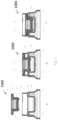
- Example 1 relates to a pressure control system 1000 in which the stopper is in hat shape 80 and the fluid connection 90 is located above the chamber for maintaining a propellant under a predetermined working pressure 100, after receiving the system in a fluid container.
- Fig. 1 A loose parts
- Fig. 1 B assembled parts, fluid connection open
- Fig. 1 C assembled parts, fluid connection closed.
- the part with fluid connection 90 has a recessed cylinder 110 for receiving the hat shaped stopper 80.
- the rim of the hat shape 180 is used to act on the fluid connection 90.
- a rim 170 is provided at the bottom of the stopper 170 to seal the reference pressure chamber 100.
- the movement of the stopper 80 is restricted by an undercut 160 in the open end of a wall located at the top of the cylinder 100. The wall controls the hat rim. Tilting of the stopper 80 is prevented.
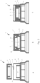
- Example 2 relates to a schematic representation of a pressure control system in which the stopper is inverted U-shaped and in which the fluid connection is located below the chamber for maintaining a propellant under a predetermined working pressure.
- Fig. 2 A the individual parts are shown.
- Fig. 2 B the assembled pressure control device with an open fluid connection is provided.
- Fig. 2 C the assembled pressure control device is depicted with the fluid connection closed.
- the pressure control system 1 uses an inverted U-shaped stopper 8 and a cylinder part 40 for receiving the stopper 8.
- An undercut 60 is provided in the opening at the top of the cylinder 40. After taking up the stopper 8, the undercut 60 ensures that the stopper will not shear out of the part when it is under pressure in use and compressed air pushes the stopper up.
- the part also has a second cylinder 41 which, together with the first cylinder 40, provides guidance for the legs of the inverted U-shaped stopper 8. This ensures good positioning and guidance of the stopper 8.
- the proposed system is compact and reliable.
- the inverted U-shaped stopper 8 has its opening directed towards the open end of cylinders 40 and 41 and is placed in the slots formed between the two concentric cylinders.
- An end 70 of one of the legs of the U-shape, viewed in cross-section, is used as a sealant to act on the fluid compound 9.
- the stopper 8 sits below the edges of the undercut 60.
- the stopper sits against the fluid connection 9 and the connection is closed. In operative condition, no gas can flow through the fluid connection towards the dispensing head of the aerosol dispenser.
- the heights of the walls in the smallest diameter cylinder 41 are matched to the height of the legs in the inverted U-shaped stopper 8 so that it can close the fluid connection.
- the U-shaped stopper includes a cylinder having a closed end in the bottom of the U-shape and an open end at the opposite end of the cylinder. At the open end there is a thickened rim 5. This rim is provided to seal the open end of the smallest diameter cylinder 41 in the disk with fluid connection 9 upon assembly.
- the reference pressure chamber 4 is formed. The volume of chamber 4 determines the working pressure with which the aerosol will operate in operative condition.
- Example 3 relates to an alternative pressure control system in which the stopper is inverted U-shaped and in which the fluid connection is located below the chamber for maintaining a propellant under a predetermined working pressure.
- Fig. 3 A the individual parts are shown.
- Fig. 3 B the assembled pressure control device 1' with an open fluid connection 9' is provided.
- Fig. 3 C the assembled pressure control device 1' is depicted with the fluid connection 9' closed.
- the pressure control device 1' comprises: a cylinder 40' having an open end and a closed end adapted to receive the stopper 8' in a form-fitting manner.
- the stopper 8' is movably received in said cylinder 40' defining a reference pressure chamber 4'.
- a propellant gas preferably compressed air
- the pressure control device 1' further comprises a sealing element 70' movable relative to the cylinder 41' for releasing and sealing said fluid connection 9' wherein, in use, the fluid connection 9' is released when the pressure in the fluid container (not shown) falls below the predetermined working pressure, propellant flows towards the dispensing head (not shown) and the pressure in the fluid container rises to the operating pressure and then the fluid connection 9' is closed by the sealing element 70' as a result of the increased pressure in the fluid container.
- Said fluid connection 9' is provided opposite to said closing element 70', so that the fluid connection can be opened and closed.
- the stopper 8' is inverted U-shaped. When assembled, the stopper 8' is inserted into cylinders 40' and 41' with the open end of the U-shape towards fluid connection 9'. The stopper end 70' of the U-shaped stopper is positioned opposite the fluid connection 9' to act on the fluid connection for opening or closing.
- a clearance 50' is sufficient to allow propellant gas to flow from the open fluid connection towards the dispensing head.
- a constant predetermined working pressure can be maintained in an aerosol can containing the system.
- Example 4 relates to an additional alternative pressure control system in which the stopper 8" is inverted U-shaped and in which the fluid connection 9" is located below the chamber for maintaining a propellant under a predetermined working pressure.
- the pressure control device 1" comprises: a first cylinder 40" having an open end and a closed end adapted to receive a stopper 8" in a form-fitting manner.
- the pressure control device further comprises a second cylinder 41" with an open end and a closed end, concentric with the first cylinder 40".
- the stopper 8" is movably receivable ( Fig. 4. A )/received ( Fig. 4 B and C ) in said cylinders 40" and 41" thereby defining a reference pressure chamber 41".
- a thickened edge 5" is provided at the open end of the stopper 8".
- the thickened rim is on the inside of the stopper 8" and slides over the rim of a cylinder 41" with a smaller diameter than cylinder 40".
- a stem is provided in the centre of the stopper 8". This is inserted into the cylinder with smallest diameter 41". When the stem is inserted into the cylinder 41" of smallest diameter, the reference pressure chamber 41" is formed.
- the dimensions of the stopper 8" and cylinder walls are matched to each other for proper operation of the pressure control device 1".
- the fluid connection is in line with the wall at the bottom of reference pressure chamber 41".
- the pressure control device 1" further comprises a sealing element 70" movable relative to the cylinder 41" for releasing and sealing said fluid connection 9" wherein, in use, the fluid connection 9" is released when the pressure in the fluid container (not shown) falls below the predetermined working pressure, propellant flows towards the dispensing head (not shown) and the pressure in the fluid container rises to the operating pressure and then the fluid connection 9" is closed by the sealing element 70" as a result of the increased pressure in the fluid container
- Said fluid connection 9" is provided opposite to said closing element 70", so that the fluid connection can be opened and closed.
- the stopper 8" is inverted U-shaped. When assembled, the stopper 8" is inserted into cylinder 40" with the open end of the U-shape towards fluid connection 9" ( Fig. 4 A) .
- the stopper end 70" of the U-shaped stopper is positioned opposite the fluid connection 9" to act on the fluid connection for opening ( Fig. 4 B) or closing ( Fig. 4C ).
- a clearance 50" is sufficient to allow propellant gas to flow from the open fluid connection 9" towards the dispensing head.
- a constant predetermined working pressure can be maintained in an aerosol can.
- the pressure control device is shown as a disk, without a container for storage of propellant.
- a pressurized container can be provided, beneath the fluid connection for propellant storage.
Landscapes
- Chemical & Material Sciences (AREA)
- Dispersion Chemistry (AREA)
- Engineering & Computer Science (AREA)
- Mechanical Engineering (AREA)
- Containers And Packaging Bodies Having A Special Means To Remove Contents (AREA)
Applications Claiming Priority (2)
| Application Number | Priority Date | Filing Date | Title |
|---|---|---|---|
| BE20225300A BE1030478B1 (nl) | 2022-04-21 | 2022-04-21 | Drukregelsysteem voor het behoud van een vooraf bepaalde constante werkdruk in een spuitbus |
| US17/806,452 US11851264B2 (en) | 2017-04-03 | 2022-06-10 | Disc-shaped pressure control device for pressure packaging |
Publications (1)
| Publication Number | Publication Date |
|---|---|
| EP4265540A1 true EP4265540A1 (fr) | 2023-10-25 |
Family
ID=86272506
Family Applications (1)
| Application Number | Title | Priority Date | Filing Date |
|---|---|---|---|
| EP23169299.7A Pending EP4265540A1 (fr) | 2022-04-21 | 2023-04-21 | Système de contrôle de pression pour maintenir une pression de service constante prédéterminée dans une pompe aérosol |
Country Status (1)
| Country | Link |
|---|---|
| EP (1) | EP4265540A1 (fr) |
Citations (4)
| Publication number | Priority date | Publication date | Assignee | Title |
|---|---|---|---|---|
| WO1999062791A1 (fr) | 1998-05-29 | 1999-12-09 | Packaging Technology Holding S.A. | Dispositif de commande de pression pour maintenir constante une pression predeterminee dans un recipient |
| WO2005082744A1 (fr) | 2004-01-30 | 2005-09-09 | Intelligent Packaging Systems Group S.A. | Dispositif régulateur de pression |
| EP3186166A1 (fr) | 2015-11-10 | 2017-07-05 | Gojara | Dispositif de régulation de pression, distributeur comprenant ledit dispositif de régulation de pression et procédé de fabrication |
| WO2018185652A1 (fr) * | 2017-04-03 | 2018-10-11 | Gojara Bvba | Dispositif de régulation de pression en forme de disque pour emballage sous pression |
-
2023
- 2023-04-21 EP EP23169299.7A patent/EP4265540A1/fr active Pending
Patent Citations (6)
| Publication number | Priority date | Publication date | Assignee | Title |
|---|---|---|---|---|
| WO1999062791A1 (fr) | 1998-05-29 | 1999-12-09 | Packaging Technology Holding S.A. | Dispositif de commande de pression pour maintenir constante une pression predeterminee dans un recipient |
| WO2005082744A1 (fr) | 2004-01-30 | 2005-09-09 | Intelligent Packaging Systems Group S.A. | Dispositif régulateur de pression |
| EP3186166A1 (fr) | 2015-11-10 | 2017-07-05 | Gojara | Dispositif de régulation de pression, distributeur comprenant ledit dispositif de régulation de pression et procédé de fabrication |
| US20180229920A1 (en) * | 2015-11-10 | 2018-08-16 | Gojara Bvba | Pressure control device, dispenser comprising said pressure control device and method of manufacturing |
| WO2018185652A1 (fr) * | 2017-04-03 | 2018-10-11 | Gojara Bvba | Dispositif de régulation de pression en forme de disque pour emballage sous pression |
| EP3619141A1 (fr) | 2017-04-03 | 2020-03-11 | Gojara BVBA | Dispositif de régulation de pression en forme de disque pour emballage sous pression |
Similar Documents
| Publication | Publication Date | Title |
|---|---|---|
| RU2722985C2 (ru) | Устройство для регулирования давления, дозатор, содержащий указанное устройство для регулирования давления, и способ производства | |
| RU2368559C2 (ru) | Устройство и способ для наполнения аэрозольных защитных упаковок с пакетом на клапане | |
| EP1725476B1 (fr) | Dispositif regulateur de pression | |
| EP2709915B1 (fr) | Procédé de remplissage et de fermeture étanche d'un générateur d'aérosol | |
| EP1622818B1 (fr) | Aerosol avec valve de distribution pour produits multi-composants | |
| EP3619141B1 (fr) | Dispositif de régulation de pression en forme de disque pour emballage sous pression | |
| EP2183055B1 (fr) | Soupapes en matière plastique et procédés d'utilisation de celles-ci | |
| JP2022514641A (ja) | 容器、クロージャ、及び製造方法 | |
| US3161330A (en) | Aerosol dispenser having a wall-surrounded valve actuator button | |
| EP3569522B1 (fr) | Soupape en plastique cristallisé pour distributeur d'aérosol et boîtier correspondant | |
| EP3536633B1 (fr) | Tige de soupape multi-pièce pour aérosols | |
| US11851264B2 (en) | Disc-shaped pressure control device for pressure packaging | |
| EP4265540A1 (fr) | Système de contrôle de pression pour maintenir une pression de service constante prédéterminée dans une pompe aérosol | |
| BE1030478B1 (nl) | Drukregelsysteem voor het behoud van een vooraf bepaalde constante werkdruk in een spuitbus | |
| US3605791A (en) | Valve assembly for and method of fitting pressurized spraying containers | |
| EP1919800B1 (fr) | Dispositif de regulation de la pression destine a un recipient pour distribution de fluide et methode pour sa fabrication | |
| JPS62208380A (ja) | バルブアセンブリおよびバルブアセンブリに使用するアダプタ |
Legal Events
| Date | Code | Title | Description |
|---|---|---|---|
| STAA | Information on the status of an ep patent application or granted ep patent |
Free format text: STATUS: UNKNOWN |
|
| STAA | Information on the status of an ep patent application or granted ep patent |
Free format text: STATUS: THE APPLICATION HAS BEEN PUBLISHED |
|
| PUAI | Public reference made under article 153(3) epc to a published international application that has entered the european phase |
Free format text: ORIGINAL CODE: 0009012 |
|
| AK | Designated contracting states |
Kind code of ref document: A1 Designated state(s): AL AT BE BG CH CY CZ DE DK EE ES FI FR GB GR HR HU IE IS IT LI LT LU LV MC ME MK MT NL NO PL PT RO RS SE SI SK SM TR |
|
| STAA | Information on the status of an ep patent application or granted ep patent |
Free format text: STATUS: REQUEST FOR EXAMINATION WAS MADE |
|
| 17P | Request for examination filed |
Effective date: 20240430 |
|
| RBV | Designated contracting states (corrected) |
Designated state(s): AL AT BE BG CH CY CZ DE DK EE ES FI FR GB GR HR HU IE IS IT LI LT LU LV MC ME MK MT NL NO PL PT RO RS SE SI SK SM TR |