EP4265544B1 - Système de transport en bout de ligne et procédé de transport et de collecte d'un ou de plusieurs produits au moyen dudit système de transport en bout de ligne - Google Patents
Système de transport en bout de ligne et procédé de transport et de collecte d'un ou de plusieurs produits au moyen dudit système de transport en bout de ligne Download PDFInfo
- Publication number
- EP4265544B1 EP4265544B1 EP23169067.8A EP23169067A EP4265544B1 EP 4265544 B1 EP4265544 B1 EP 4265544B1 EP 23169067 A EP23169067 A EP 23169067A EP 4265544 B1 EP4265544 B1 EP 4265544B1
- Authority
- EP
- European Patent Office
- Prior art keywords
- comb
- elements
- conveyor system
- line conveyor
- products
- Prior art date
- Legal status (The legal status is an assumption and is not a legal conclusion. Google has not performed a legal analysis and makes no representation as to the accuracy of the status listed.)
- Active
Links
Images







Classifications
-
- B—PERFORMING OPERATIONS; TRANSPORTING
- B65—CONVEYING; PACKING; STORING; HANDLING THIN OR FILAMENTARY MATERIAL
- B65G—TRANSPORT OR STORAGE DEVICES, e.g. CONVEYORS FOR LOADING OR TIPPING, SHOP CONVEYOR SYSTEMS OR PNEUMATIC TUBE CONVEYORS
- B65G15/00—Conveyors having endless load-conveying surfaces, i.e. belts and like continuous members, to which tractive effort is transmitted by means other than endless driving elements of similar configuration
- B65G15/10—Conveyors having endless load-conveying surfaces, i.e. belts and like continuous members, to which tractive effort is transmitted by means other than endless driving elements of similar configuration comprising two or more co-operating endless surfaces with parallel longitudinal axes, or a multiplicity of parallel elements, e.g. ropes defining an endless surface
- B65G15/12—Conveyors having endless load-conveying surfaces, i.e. belts and like continuous members, to which tractive effort is transmitted by means other than endless driving elements of similar configuration comprising two or more co-operating endless surfaces with parallel longitudinal axes, or a multiplicity of parallel elements, e.g. ropes defining an endless surface with two or more endless belts
-
- B—PERFORMING OPERATIONS; TRANSPORTING
- B65—CONVEYING; PACKING; STORING; HANDLING THIN OR FILAMENTARY MATERIAL
- B65G—TRANSPORT OR STORAGE DEVICES, e.g. CONVEYORS FOR LOADING OR TIPPING, SHOP CONVEYOR SYSTEMS OR PNEUMATIC TUBE CONVEYORS
- B65G21/00—Supporting or protective framework or housings for endless load-carriers or traction elements of belt or chain conveyors
- B65G21/10—Supporting or protective framework or housings for endless load-carriers or traction elements of belt or chain conveyors movable, or having interchangeable or relatively movable parts; Devices for moving framework or parts thereof
- B65G21/12—Supporting or protective framework or housings for endless load-carriers or traction elements of belt or chain conveyors movable, or having interchangeable or relatively movable parts; Devices for moving framework or parts thereof to allow adjustment of position of load-carrier or traction element as a whole
Definitions
- the present invention relates to an end-of-line conveyor system defining a predefined, substantially horizontal path along which one or more products are adapted to be conveyed from an inlet point to a pick-up point.
- the invention also relates to a method for conveying one or more products along a predefined path and for picking up those products by the aforesaid end-of-line conveyor system.
- conveyor systems may also be arranged at the initial position or at intermediate positions of these production plants, between one processing unit and the following one.
- end-of-line conveyor system is not to be understood as exclusively encompassing conveyor systems arranged at the outlet of a production plant, but should also be understood to refer to those conveyor systems arranged at intermediate positions in a production plant.
- such conveyor systems in order to fulfil the aforesaid task and enable picking up the products, are provided with a support structure defining the aforesaid predefined path and at least one handling kinematic mechanism associated with this support structure and configured to move these products from said inlet point to the pick-up point.
- the prior art end-of-line conveyor systems comprise a lifting unit capable of lifting said products and releasing them from said handling kinematic mechanism, so as to intervene with the forks of a forklift between the same handling kinematic mechanism and the product in order to pick up the latter.
- the lifting unit in order to allow an operator to pick up the aforesaid products from the end-of-line conveyor system, the lifting unit is provided with suitable free passages along its length, in order to allow a pair of forks belonging to the aforesaid forklift to be inserted from either side of the conveyor system.
- the lifting units according to the prior art have such free passages with a predetermined size and spacing.
- lifting units are only suitable for one or limited types of products of a predefined size. Therefore, disadvantageously, when it is required to convey products of different sizes and types by means of the same conveyor system, these lifting units must be suitably adapted and pre-configured before starting the production of the new batch of products. Moreover, still disadvantageously, it is not excluded that, during the same production batch, the products to be conveyed are of different types, such as different components of a single complex system. In this case, such a static approach is not at all suitable to fulfil the task of making it possible to pick up said products of different types.
- a solution of the prior art provides to create lifting units configured and shaped to support and make it possible to pick up products of various sizes, by inserting pairs of forks with different pitches.
- the present invention intends to overcome the aforesaid drawbacks of the prior art.
- the object of the invention is to create a universal end-of-line conveyor system capable of handling any type of product format.
- the object of the invention is to create an end-of-line conveyor system that does not require any adjustments and changes in the format in order to handle different types of products.
- the object of the invention is to create an end-of-line conveyor system capable of automatically adapting to different types of products, even during the same production batch.
- the end-of-line conveyor system while being able to universally handle different types of products, has a simplified structure and is therefore little prone to wear and malfunction.
- Figs. 8 to 14 show the steps of the method of the invention, implemented by means of the end-of-line conveyor system of the invention of Fig. 1 .
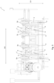
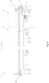
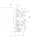
- the end-of-line conveyor system of the invention is represented in Figs. 1 to 4 , where it is globally referred to as 1.
- Such an end-of-line conveyor system defines a predefined path T that is substantially horizontal, along which one or more products O are adapted to be conveyed from an inlet point PI to a pick-up point PO.
- the end-of-line conveyor system 1 comprises a support structure 2 defining such predefined path T.
- such an end-of-line conveyor system 1 also comprises four handling kinematic mechanisms, globally referred to as 3 and individually as 3a, 3b, 3c and 3d , associated with the support structure 2 and arranged parallel to each other along such predefined path T.
- Each of the aforesaid four handling kinematic mechanisms 3a, 3b, 3c and 3d is configured to contribute to moving products O from the inlet point PI to the pick-up point PO.
- the end-of-line conveyor system 1 comprises a single handling kinematic mechanism 3 or comprises a plurality of handling kinematic mechanisms 3 in a number other than four, always arranged parallel to each other along such predefined path T.
- the end-of-line conveyor system 1 is not provided with such handling kinematic mechanisms 3.
- each of the aforesaid four handling kinematic mechanisms 3a, 3b, 3c and 3d comprises a catenary system 31, capable of feeding, when supported on the latter, the products O along the aforesaid predefined path T.
- each of the aforesaid four handling kinematic mechanisms 3a, 3b, 3c and 3d could comprise a belt system or any other mechanical system capable of feeding the aforesaid products O along the predefined path T.
- the end-of-line conveyor system 1 comprises two lifting units, globally referred to as 4 and individually as 4a and 4b, associated with the support structure 2 and arranged parallel to each other along said predefined path T.
- each of the aforementioned two lifting units 4a and 4b is arranged between two of the aforementioned handling kinematic mechanisms 3 adjacent to each other, in particular, the first lifting unit 4a is interposed between the first handling kinematic mechanism 3a and the second handling kinematic mechanism 3b, while the second lifting unit 4b is interposed between the third handling kinematic mechanism 3c and the fourth handling kinematic mechanism 3d.
- the end-of-line conveyor system 1 may comprise a different number of lifting units 4.
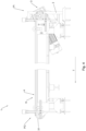
- each of the aforesaid lifting units 4 is configured to lift and disengage the products O from the handling kinematic mechanism 3, so that these products O can be picked up from the end-of-line conveyor system 1 by means of appropriate external forklifts CE provided with forks F or similar gripping systems.
- each of the aforesaid lifting units 4 comprises a lifting base 5 operatively associated with the support structure 2, so that it can be moved in a vertical direction DV relative to the same support structure 2.
- each of the aforesaid lifting units 4 provides that its lifting base 5 extends along the predefined path T, preferably along the entire predefined path T.
- each lifting unit 4 in order to implement the aforesaid movement of the lifting base 5 relative to the support structure 2, in both directions, along said vertical direction DV, each lifting unit 4 comprises a plurality of hydraulic or pneumatic pistons 9 operatively associated with the same lifting base 5.
- each lifting unit 4 may be provided with different types of actuators, of the type known in itself, such as electric lifting systems, in particular geared motors or the like, capable of moving the aforesaid lifting base 5 of each lifting unit 4 along the vertical direction DV, relative to the support structure 2.
- actuators of the type known in itself, such as electric lifting systems, in particular geared motors or the like, capable of moving the aforesaid lifting base 5 of each lifting unit 4 along the vertical direction DV, relative to the support structure 2.
- Each lifting unit 4 is also provided with a plurality of comb-like elements 6, each, as it can be seen in Fig. 5 , substantially extending along a longitudinal axis X.
- Such comb-like elements 6 can also be rotated in the opposite direction, from the aforesaid forced position to the rest position, as will be described in detail hereinafter.
- each of such comb-like elements 6, according to a plane orthogonal ⁇ to the rotation axis Y, has along said longitudinal axis X a first end section 61 with an asymmetrical shape, and a second end section 62 with a symmetrical shape, joined to each other by an interconnection section 63, wherein an oblique side 8 with respect to the longitudinal axis X is identified.
- the first end section 61 is freely hinged in an off-centred position to the lifting base 5 at the oblique side 8, such that each of said comb-like elements 6 is configured to rotate, at the oblique side 8, by an angle in the region of 90° about the rotation axis Y, from the rest position to said forced position.
- each of these comb-like elements 6 is also able to rotate by the aforesaid 90° angle, about the rotation axis Y, in the opposite direction so as to be able to switch from the aforesaid forced position to the rest position.
- the fact that the comb-like elements 6 are hinged in an off-centred position at the first end section 61 makes it possible to facilitate the return of the same comb-like elements 6 from the forced position to the rest position, exploiting the unbalance of the weights precisely due to this off-centred hinge.
- each lifting unit 4 comprises return means 7 configured to move the plurality of comb-like elements 6 from the forced position to the rest position.
- the return means 7 comprise a cylindrical contrast bar 71 arranged along the predefined path T, adjacent to the comb-like elements 6, at the oblique sides 8.
- this cylindrical contrast bar 71 is configured to progressively contact the first asymmetrical section 61, the oblique side 8 of the interconnection section 63 and the second symmetrical section 62 of the comb-like elements 6 arranged at the second position, while lowering the lifting unit 4. The rotation of the same comb-like elements 6 from the forced position to the rest position is thereby mechanically induced.
- such return means 7 could comprise elastic elements configured to induce the rotation of the comb-like elements 6 from the aforesaid forced position to the rest position.
- the method for conveying one or more products O along a predefined path T and for picking up those products O using the end-of-line conveyor system of the invention comprises the steps described hereinafter.
- the method involves loading products O at an inlet point PI of the end-of-line conveyor system 1, by means of interposing laths L or pallets P between the handling kinematic mechanisms 3 and each product O.
- the method also provides handling these products O along the aforesaid predefined path T from the inlet point PI to a pick-up point PO, activating the aforesaid handling kinematic mechanisms 3, always as schematised in Fig. 8 .
- the method of the invention provides for deactivating the handling kinematic mechanisms 3 and lifting the lifting units 4, so as to lift and disengage the same product O from such handling kinematic mechanisms 3, as schematised in Fig. 10 .
- the comb-like elements 6 are all arranged in the aforesaid rest position, and those arranged below the laths L or the pallets P, supporting the product O, come into contact with the lower surfaces SI of the same laths L or pallets P, raising the product O relative to the handling kinematic mechanism 3.
- the fact that such comb-like elements 6 engage with the lower surfaces SI of the laths L or of the pallets P prevents the former, arranged in the aforesaid rest position, from rotating freely in the forced position.
- the comb-like elements 6 located along a predefined path T at different positions from the positions below the laths L and pallets P, remain disengaged from any hindrance and therefore in a free rotation configuration.
- the product O present at the aforesaid pick-up point PO can be picked up by an operator, using a forklift CE provided with forks F.
- the operator has the possibility of inserting the aforesaid forks F, suitably spaced according to the type of product O to be picked up, in particular according to the distance of the laths L or the design of the pallets P, in a direction orthogonal to the rotation axis Y, opposite to the oblique sides 8 of the comb-like elements 6.
- Such insertion must obviously be carried out at positions along the predefined path T that do not correspond to the positions of the same laths L or pallets P.
- the method of the invention provides for lowering the lifting units 3 along the aforesaid vertical direction DV and, in so doing, as it can be observed in the sequence of Figures 12 to 14 , the comb-like elements 6 arranged in the aforesaid forced position progressively come into contact with the return means 7, in particular with the cylindrical contrast bar 71, and are induced by the latter to rotate and assume the rest position.
- the lifting units 4 of the end-of-line conveyor system 1 of the invention are thereby arranged in their lowered position, with all the comb-like elements 6 positioned in their rest position, ready for a new convey and pick-up cycle of products O.
Landscapes
- Engineering & Computer Science (AREA)
- Mechanical Engineering (AREA)
- Specific Conveyance Elements (AREA)
Claims (10)
- Système de convoyage de fin de ligne (1) définissant une trajectoire prédéfinie (T) essentiellement horizontale, le long de laquelle un ou plusieurs produits (O) sont adaptés pour être transportés d'un point d'entrée (PI) à un point de prélèvement (PO), du type comprenant:- une structure de support (2) définissant ladite trajectoire prédéfinie (T);- au moins un mécanisme cinématique de manutention (3, 3a, 3b, 3c, 3d) associé à ladite structure de support (2) et configuré pour déplacer lesdits produits (O) dudit point d'entrée (PI) vers ledit point de prélèvement (PO);- une unité de levage (4, 4a, 4b) associée à ladite structure de support (2) et configurée pour soulever et désengager lesdits produits (O) par rapport audit mécanisme cinématique de manutention (3, 3a, 3b, 3c, 3d), afin que lesdits produits (O) puissent être prélevés dudit système de convoyage de fin de ligne (1) au moyen de chariots élévateurs externes (CE);où ladite unité de levage (4, 4a, 4b) comprend:- une base de levage (5) associée de manière opérationnelle à ladite structure de support (2) afin qu'elle puisse être déplacée dans une direction verticale (DV), ladite base de levage (5) s'étendant le long de ladite trajectoire prédéfinie (T);- une pluralité d'éléments en forme de peigne (6), chacun s'étendant sensiblement le long d'un axe longitudinal (X),caractérisés en ce que lesdits éléments en forme de peigne (6) sont librement articulés à ladite base de levage (5), l'un après l'autre, le long de ladite trajectoire prédéfinie (T) selon un axe de rotation (Y) parallèle à ladite trajectoire prédéfinie (T), de sorte que chacun desdits éléments en forme de peigne (6), indépendamment desdits éléments en forme de peigne restants (6), puisse tourner d'une première position de repos, selon laquelle ledit axe longitudinal (X) est parallèle à ladite direction verticale (DV), à une deuxième position forcée, selon laquelle ledit axe longitudinal (X) est parallèle à la direction horizontale (DO), et vice versa;et caractérisé en outre en ce que ladite unité de levage comprend également- des moyens de retour (7) configurés pour déplacer ladite pluralité d'éléments en forme de peigne (6) de ladite deuxième position forcée à ladite première position de repos.
- Système de convoyage de fin de ligne (1) selon la revendication 1, caractérisé en ce que chacun desdits éléments en forme de peigne (6), selon un plan orthogonal (π) audit axe de rotation (Y), présente, le long dudit axe longitudinal (X), une première section d'extrémité (61) de forme asymétrique et une deuxième section d'extrémité (62) de forme symétrique, reliées l'une à l'autre par une section d'interconnexion (63) dans laquelle un côté oblique (8) par rapport audit axe longitudinal (X) est identifié, ladite première section d'extrémité (61) étant articulée en position décentrée sur ladite base de levage (5) au niveau dudit côté oblique (8), chacun desdits éléments en forme de peigne (6) étant configuré pour tourner d'un angle de l'ordre de 90° autour dudit axe de rotation (Y), au niveau dudit côté oblique (8), de ladite première position de repos à ladite deuxième position forcée.
- Système de convoyage de fin de ligne (1) selon la revendication 2, caractérisé en ce que lesdits moyens de retour (7) comprennent une barre de contraste cylindrique (71) disposée le long de ladite trajectoire prédéfinie (T), adjacente auxdits éléments en forme de peigne (6) au niveau desdits côtés obliques (8), ladite barre de contraste cylindrique (71) étant configurée pour entrer progressivement en contact avec ladite première section asymétrique (61), ledit côté oblique (8) de ladite section d'interconnexion (63) et ladite deuxième section symétrique (62) desdits éléments en forme de peigne (6) disposés dans ladite deuxième position tout en abaissant ladite unité de levage (4, 4a, 4b) de manière à forcer la rotation desdits éléments en forme de peigne (6) de ladite position forcée à ladite position de repos.
- Système de convoyage de fin de ligne (1) selon l'une quelconque des revendications 1 ou 2, caractérisé en ce que lesdits moyens de retour (7) comprennent des éléments élastiques (72) configurés pour forcer la rotation desdits éléments en forme de peigne (6) de ladite position forcée à ladite position de repos.
- Système de convoyage de fin de ligne (1) selon l'une quelconque des revendications précédentes, caractérisé en ce qu'il comprend quatre mécanismes cinématiques de manutention (3, 3a, 3b, 3c, 3d) disposés parallèlement les uns aux autres le long de ladite trajectoire prédéfinie (T), ladite unité de levage (4, 4a, 4b) étant définie comme étant interposée entre deux paires adjacentes desdits quatre mécanismes cinématiques de manutention (3, 3a, 3b, 3c, 3d).
- Système de convoyage de fin de ligne (1) selon l'une quelconque des revendications précédentes, caractérisé en ce qu'il comprend deux unités de levage (4, 4a, 4b) disposées parallèlement l'une à l'autre le long de ladite trajectoire prédéfinie (T).
- Système de convoyage de fin de ligne (1) selon l'une quelconque des revendications précédentes, caractérisé en ce que ledit mécanisme cinématique de manutention (3, 3a, 3b, 3c, 3d) est un système de caténaire (31).
- Système de convoyage de fin de ligne (1) selon l'une quelconque des revendications 1 à 6, caractérisé en ce que ledit mécanisme cinématique de manutention (3, 3a, 3b, 3c, 3d) est un système à courroie.
- Système de convoyage de fin de ligne (1) selon la revendication 1, caractérisé en ce que ladite unité de levage (4, 4a, 4b) comprend une pluralité de pistons hydrauliques ou pneumatiques (9) configurés pour déplacer ladite base de levage (5) le long de ladite direction verticale (DV).
- Procédé de convoyage d'un ou plusieurs produits (O) le long d'une trajectoire prédéfinie (T) et de prélèvement desdits produits (O) via un système de convoyage de fin de ligne (1) selon l'une quelconque des revendications précédentes, caractérisé en ce qu'il prévoit les étapes suivantes:- charger lesdits produits (O) à un point d'entrée (PI) dudit système de convoyage de fin de ligne (1), au moyen de lattes (L) ou de palettes (P);- déplacer lesdits produits le long de ladite trajectoire prédéfinie (T) dudit point d'entrée (PI) à un point de prélèvement (PO) en activant lesdits mécanismes cinématiques de manutention (3, 3a, 3b, 3c, 3d);- lorsque ledit produit (O) est disposé audit point de prélèvement (PO), désactiver ledit mécanisme cinématique de manutention (3, 3a, 3b, 3c, 3d) et soulever ladite unité de levage (4, 4a, 4b) de manière à désengager ledit produit dudit mécanisme cinématique de manutention (3, 3a, 3b, 3c, 3d); pendant ledit levage, les éléments en forme de peigne (6) disposés dans ladite position de repos, sous lesdites lattes (L) ou lesdites palettes (P), entrent en contact avec les surfaces inférieures (SI) desdites lattes (L) ou desdites palettes (P), en soulevant lesdits produits (O), tandis que les éléments en forme de peigne (6) disposés dans différentes positions le long de ladite trajectoire prédéfinie (T) restent dans une configuration de rotation libre;- insérer dans une direction orthogonale (DO) audit axe de rotation (Y), en face desdits côtés obliques (8) desdits éléments en forme de peigne (6), les fourches (F) d'un chariot élévateur externe (CE), à différentes positions le long de ladite trajectoire prédéfinie (T) par rapport à la position desdites lattes (L) ou desdites palettes (P), ladite insertion déterminant la rotation desdits éléments en forme de peigne (6) auxdites différentes positions, de ladite position de repos à ladite position forcée;- lorsque lesdites fourches (F) sont complètement insérées, soulever ledit produit (O) au moyen dudit chariot élévateur externe (CE) afin de prélever ledit produit (O);- une fois que ledit produit (O) a été prélevé, abaisser ladite unité de levage (4, 4a, 4b) le long de la direction verticale (DV), ledit abaissement déterminant la rotation desdits éléments en forme de peigne (6) disposés dans ladite position forcée, de ladite position forcée à ladite position de repos, par ledit moyen de retour (7).
Applications Claiming Priority (1)
| Application Number | Priority Date | Filing Date | Title |
|---|---|---|---|
| IT102022000007982A IT202200007982A1 (it) | 2022-04-22 | 2022-04-22 | Sistema di trasporto di fine linea e metodo per il trasporto e per il prelievo di uno o più prodotti mediante detto sistema di trasporto di fine linea |
Publications (3)
| Publication Number | Publication Date |
|---|---|
| EP4265544A1 EP4265544A1 (fr) | 2023-10-25 |
| EP4265544B1 true EP4265544B1 (fr) | 2024-12-25 |
| EP4265544C0 EP4265544C0 (fr) | 2024-12-25 |
Family
ID=82694132
Family Applications (1)
| Application Number | Title | Priority Date | Filing Date |
|---|---|---|---|
| EP23169067.8A Active EP4265544B1 (fr) | 2022-04-22 | 2023-04-20 | Système de transport en bout de ligne et procédé de transport et de collecte d'un ou de plusieurs produits au moyen dudit système de transport en bout de ligne |
Country Status (2)
| Country | Link |
|---|---|
| EP (1) | EP4265544B1 (fr) |
| IT (1) | IT202200007982A1 (fr) |
Family Cites Families (3)
| Publication number | Priority date | Publication date | Assignee | Title |
|---|---|---|---|---|
| US3151754A (en) * | 1961-03-28 | 1964-10-06 | Jr John H Kemp | Apparatus for transferring loads |
| US3967737A (en) * | 1974-08-19 | 1976-07-06 | Conveyor Systems, Inc. | Depalletizing and pallet stacking apparatus |
| ITBO20120353A1 (it) * | 2012-06-26 | 2013-12-27 | Gruppo Fabbri Vignola Spa | Apparato per l'alimentazione ordinata di gruppi di vassoi ad una macchina adibita alla sigillatura dei vassoi stessi con l'applicazione di un film di copertura |
-
2022
- 2022-04-22 IT IT102022000007982A patent/IT202200007982A1/it unknown
-
2023
- 2023-04-20 EP EP23169067.8A patent/EP4265544B1/fr active Active
Also Published As
| Publication number | Publication date |
|---|---|
| IT202200007982A1 (it) | 2023-10-22 |
| EP4265544A1 (fr) | 2023-10-25 |
| EP4265544C0 (fr) | 2024-12-25 |
Similar Documents
| Publication | Publication Date | Title |
|---|---|---|
| CN109110511A (zh) | 一种托盘自动拆码垛机构及自动拆码垛方法 | |
| EP3354607B1 (fr) | Dispositif d'empilage automatisé universel | |
| CN218809100U (zh) | 一种码垛机 | |
| EP2397428A1 (fr) | Appareil et procédé pour empiler des unités d' emballage | |
| EP3810529B1 (fr) | Système et procédé automatisés pour le stockage et le déplacement d'un matériau lourd | |
| EP3313760A1 (fr) | Dispositif de rangement pour produits en céramique et analogues | |
| CN210456572U (zh) | 送料装置 | |
| US5064330A (en) | Belt-shaped member taking-out and transfer apparatus | |
| EP4265544B1 (fr) | Système de transport en bout de ligne et procédé de transport et de collecte d'un ou de plusieurs produits au moyen dudit système de transport en bout de ligne | |
| EP3450362B1 (fr) | Dispositif pour charger un groupe de produits sur une palette | |
| CN110282183A (zh) | 条形物无损高速码垛装置 | |
| EP3464139B1 (fr) | Extracteur de feuilles d'une pile | |
| EP3612477B1 (fr) | Pince pour couches d'articles | |
| WO1997003006A1 (fr) | Ensemble a deux bras d'empilage de bois d'oeuvre | |
| CN108483316B (zh) | 一种物料的转运装置 | |
| EP3466853B1 (fr) | Unité d'alimentation d'éléments lamellaires dans un dispositif d'introduction | |
| EP2377789B1 (fr) | Dispositif de transfert d'oeufs de type parallélogramme | |
| CN114348617A (zh) | 一种用于板材运输的生产线 | |
| EP2722297B1 (fr) | Machine de découpe d'une feuille de verre laminée comprenant une station tampon équipée de moyen de transport | |
| EP3464125B1 (fr) | Unité de préparation de piles à tourne-pile | |
| EP3464129B1 (fr) | Transporteur | |
| CN216996451U (zh) | 一种用于板材运输的生产线 | |
| CN113983778B (zh) | 全自动平躺式烘烤线 | |
| KR20200102866A (ko) | 파렛트 승강작동에 의하여 제품 적재가 이루어지는 자동 적재장치 | |
| JP7333048B2 (ja) | トレイ取扱装置 |
Legal Events
| Date | Code | Title | Description |
|---|---|---|---|
| PUAI | Public reference made under article 153(3) epc to a published international application that has entered the european phase |
Free format text: ORIGINAL CODE: 0009012 |
|
| STAA | Information on the status of an ep patent application or granted ep patent |
Free format text: STATUS: THE APPLICATION HAS BEEN PUBLISHED |
|
| AK | Designated contracting states |
Kind code of ref document: A1 Designated state(s): AL AT BE BG CH CY CZ DE DK EE ES FI FR GB GR HR HU IE IS IT LI LT LU LV MC ME MK MT NL NO PL PT RO RS SE SI SK SM TR |
|
| STAA | Information on the status of an ep patent application or granted ep patent |
Free format text: STATUS: REQUEST FOR EXAMINATION WAS MADE |
|
| 17P | Request for examination filed |
Effective date: 20240329 |
|
| RBV | Designated contracting states (corrected) |
Designated state(s): AL AT BE BG CH CY CZ DE DK EE ES FI FR GB GR HR HU IE IS IT LI LT LU LV MC ME MK MT NL NO PL PT RO RS SE SI SK SM TR |
|
| GRAP | Despatch of communication of intention to grant a patent |
Free format text: ORIGINAL CODE: EPIDOSNIGR1 |
|
| STAA | Information on the status of an ep patent application or granted ep patent |
Free format text: STATUS: GRANT OF PATENT IS INTENDED |
|
| INTG | Intention to grant announced |
Effective date: 20240716 |
|
| GRAS | Grant fee paid |
Free format text: ORIGINAL CODE: EPIDOSNIGR3 |
|
| GRAA | (expected) grant |
Free format text: ORIGINAL CODE: 0009210 |
|
| STAA | Information on the status of an ep patent application or granted ep patent |
Free format text: STATUS: THE PATENT HAS BEEN GRANTED |
|
| AK | Designated contracting states |
Kind code of ref document: B1 Designated state(s): AL AT BE BG CH CY CZ DE DK EE ES FI FR GB GR HR HU IE IS IT LI LT LU LV MC ME MK MT NL NO PL PT RO RS SE SI SK SM TR |
|
| REG | Reference to a national code |
Ref country code: GB Ref legal event code: FG4D |
|
| REG | Reference to a national code |
Ref country code: CH Ref legal event code: EP |
|
| REG | Reference to a national code |
Ref country code: DE Ref legal event code: R096 Ref document number: 602023001456 Country of ref document: DE |
|
| REG | Reference to a national code |
Ref country code: IE Ref legal event code: FG4D |
|
| U01 | Request for unitary effect filed |
Effective date: 20250122 |
|
| U07 | Unitary effect registered |
Designated state(s): AT BE BG DE DK EE FI FR IT LT LU LV MT NL PT RO SE SI Effective date: 20250128 |
|
| PG25 | Lapsed in a contracting state [announced via postgrant information from national office to epo] |
Ref country code: NO Free format text: LAPSE BECAUSE OF FAILURE TO SUBMIT A TRANSLATION OF THE DESCRIPTION OR TO PAY THE FEE WITHIN THE PRESCRIBED TIME-LIMIT Effective date: 20250325 |
|
| PG25 | Lapsed in a contracting state [announced via postgrant information from national office to epo] |
Ref country code: GR Free format text: LAPSE BECAUSE OF FAILURE TO SUBMIT A TRANSLATION OF THE DESCRIPTION OR TO PAY THE FEE WITHIN THE PRESCRIBED TIME-LIMIT Effective date: 20250326 |
|
| PG25 | Lapsed in a contracting state [announced via postgrant information from national office to epo] |
Ref country code: RS Free format text: LAPSE BECAUSE OF FAILURE TO SUBMIT A TRANSLATION OF THE DESCRIPTION OR TO PAY THE FEE WITHIN THE PRESCRIBED TIME-LIMIT Effective date: 20250325 |
|
| U20 | Renewal fee for the european patent with unitary effect paid |
Year of fee payment: 3 Effective date: 20250425 |
|
| PG25 | Lapsed in a contracting state [announced via postgrant information from national office to epo] |
Ref country code: SM Free format text: LAPSE BECAUSE OF FAILURE TO SUBMIT A TRANSLATION OF THE DESCRIPTION OR TO PAY THE FEE WITHIN THE PRESCRIBED TIME-LIMIT Effective date: 20241225 |
|
| PG25 | Lapsed in a contracting state [announced via postgrant information from national office to epo] |
Ref country code: PL Free format text: LAPSE BECAUSE OF FAILURE TO SUBMIT A TRANSLATION OF THE DESCRIPTION OR TO PAY THE FEE WITHIN THE PRESCRIBED TIME-LIMIT Effective date: 20241225 |
|
| PG25 | Lapsed in a contracting state [announced via postgrant information from national office to epo] |
Ref country code: ES Free format text: LAPSE BECAUSE OF FAILURE TO SUBMIT A TRANSLATION OF THE DESCRIPTION OR TO PAY THE FEE WITHIN THE PRESCRIBED TIME-LIMIT Effective date: 20241225 |
|
| PG25 | Lapsed in a contracting state [announced via postgrant information from national office to epo] |
Ref country code: IS Free format text: LAPSE BECAUSE OF FAILURE TO SUBMIT A TRANSLATION OF THE DESCRIPTION OR TO PAY THE FEE WITHIN THE PRESCRIBED TIME-LIMIT Effective date: 20250425 |
|
| PG25 | Lapsed in a contracting state [announced via postgrant information from national office to epo] |
Ref country code: SK Free format text: LAPSE BECAUSE OF FAILURE TO SUBMIT A TRANSLATION OF THE DESCRIPTION OR TO PAY THE FEE WITHIN THE PRESCRIBED TIME-LIMIT Effective date: 20241225 |
|
| PG25 | Lapsed in a contracting state [announced via postgrant information from national office to epo] |
Ref country code: CZ Free format text: LAPSE BECAUSE OF FAILURE TO SUBMIT A TRANSLATION OF THE DESCRIPTION OR TO PAY THE FEE WITHIN THE PRESCRIBED TIME-LIMIT Effective date: 20241225 |
|
| PLBE | No opposition filed within time limit |
Free format text: ORIGINAL CODE: 0009261 |
|
| STAA | Information on the status of an ep patent application or granted ep patent |
Free format text: STATUS: NO OPPOSITION FILED WITHIN TIME LIMIT |
|
| 26N | No opposition filed |
Effective date: 20250926 |
|
| PG25 | Lapsed in a contracting state [announced via postgrant information from national office to epo] |
Ref country code: MC Free format text: LAPSE BECAUSE OF FAILURE TO SUBMIT A TRANSLATION OF THE DESCRIPTION OR TO PAY THE FEE WITHIN THE PRESCRIBED TIME-LIMIT Effective date: 20241225 |
|
| PG25 | Lapsed in a contracting state [announced via postgrant information from national office to epo] |
Ref country code: IE Free format text: LAPSE BECAUSE OF NON-PAYMENT OF DUE FEES Effective date: 20250420 |
|
| PG25 | Lapsed in a contracting state [announced via postgrant information from national office to epo] |
Ref country code: HR Free format text: LAPSE BECAUSE OF FAILURE TO SUBMIT A TRANSLATION OF THE DESCRIPTION OR TO PAY THE FEE WITHIN THE PRESCRIBED TIME-LIMIT Effective date: 20241225 |