EP4265550A1 - Vorrichtung zum lagern, transportieren und installieren von elektrischen drähten und kabeln - Google Patents
Vorrichtung zum lagern, transportieren und installieren von elektrischen drähten und kabeln Download PDFInfo
- Publication number
- EP4265550A1 EP4265550A1 EP23164197.8A EP23164197A EP4265550A1 EP 4265550 A1 EP4265550 A1 EP 4265550A1 EP 23164197 A EP23164197 A EP 23164197A EP 4265550 A1 EP4265550 A1 EP 4265550A1
- Authority
- EP
- European Patent Office
- Prior art keywords
- plate
- cylinder
- plates
- handle
- metal tubes
- Prior art date
- Legal status (The legal status is an assumption and is not a legal conclusion. Google has not performed a legal analysis and makes no representation as to the accuracy of the status listed.)
- Granted
Links
Images


Classifications
-
- B—PERFORMING OPERATIONS; TRANSPORTING
- B65—CONVEYING; PACKING; STORING; HANDLING THIN OR FILAMENTARY MATERIAL
- B65H—HANDLING THIN OR FILAMENTARY MATERIAL, e.g. SHEETS, WEBS, CABLES
- B65H49/00—Unwinding or paying-out filamentary material; Supporting, storing or transporting packages from which filamentary material is to be withdrawn or paid-out
- B65H49/18—Methods or apparatus in which packages rotate
- B65H49/20—Package-supporting devices
- B65H49/205—Hand-held or portable dispensers
-
- B—PERFORMING OPERATIONS; TRANSPORTING
- B65—CONVEYING; PACKING; STORING; HANDLING THIN OR FILAMENTARY MATERIAL
- B65H—HANDLING THIN OR FILAMENTARY MATERIAL, e.g. SHEETS, WEBS, CABLES
- B65H49/00—Unwinding or paying-out filamentary material; Supporting, storing or transporting packages from which filamentary material is to be withdrawn or paid-out
- B65H49/18—Methods or apparatus in which packages rotate
- B65H49/20—Package-supporting devices
- B65H49/32—Stands or frameworks
- B65H49/324—Constructional details
- B65H49/328—Arrangements or adaptations for stacking
-
- B—PERFORMING OPERATIONS; TRANSPORTING
- B65—CONVEYING; PACKING; STORING; HANDLING THIN OR FILAMENTARY MATERIAL
- B65H—HANDLING THIN OR FILAMENTARY MATERIAL, e.g. SHEETS, WEBS, CABLES
- B65H49/00—Unwinding or paying-out filamentary material; Supporting, storing or transporting packages from which filamentary material is to be withdrawn or paid-out
- B65H49/36—Securing packages to supporting devices
-
- B—PERFORMING OPERATIONS; TRANSPORTING
- B65—CONVEYING; PACKING; STORING; HANDLING THIN OR FILAMENTARY MATERIAL
- B65H—HANDLING THIN OR FILAMENTARY MATERIAL, e.g. SHEETS, WEBS, CABLES
- B65H49/00—Unwinding or paying-out filamentary material; Supporting, storing or transporting packages from which filamentary material is to be withdrawn or paid-out
- B65H49/38—Skips, cages, racks, or containers, adapted solely for the transport or storage of bobbins, cops, or the like
-
- H—ELECTRICITY
- H02—GENERATION; CONVERSION OR DISTRIBUTION OF ELECTRIC POWER
- H02G—INSTALLATION OF ELECTRIC CABLES OR LINES, OR OF COMBINED OPTICAL AND ELECTRIC CABLES OR LINES
- H02G11/00—Arrangements of electric cables or lines between relatively-movable parts
- H02G11/02—Arrangements of electric cables or lines between relatively-movable parts using take-up reel or drum
-
- B—PERFORMING OPERATIONS; TRANSPORTING
- B65—CONVEYING; PACKING; STORING; HANDLING THIN OR FILAMENTARY MATERIAL
- B65H—HANDLING THIN OR FILAMENTARY MATERIAL, e.g. SHEETS, WEBS, CABLES
- B65H2402/00—Constructional details of the handling apparatus
- B65H2402/40—Details of frames, housings or mountings of the whole handling apparatus
- B65H2402/41—Portable or hand-held apparatus
- B65H2402/412—Portable or hand-held apparatus details or the parts to be hold by the user, e.g. handle
-
- B—PERFORMING OPERATIONS; TRANSPORTING
- B65—CONVEYING; PACKING; STORING; HANDLING THIN OR FILAMENTARY MATERIAL
- B65H—HANDLING THIN OR FILAMENTARY MATERIAL, e.g. SHEETS, WEBS, CABLES
- B65H2701/00—Handled material; Storage means
- B65H2701/30—Handled filamentary material
- B65H2701/34—Handled filamentary material electric cords or electric power cables
-
- B—PERFORMING OPERATIONS; TRANSPORTING
- B65—CONVEYING; PACKING; STORING; HANDLING THIN OR FILAMENTARY MATERIAL
- B65H—HANDLING THIN OR FILAMENTARY MATERIAL, e.g. SHEETS, WEBS, CABLES
- B65H2701/00—Handled material; Storage means
- B65H2701/50—Storage means for webs, tapes, or filamentary material
- B65H2701/53—Adaptations of cores or reels for special purposes
- B65H2701/534—Stackable or interlockable reels or parts of reels
Definitions
- the present invention relates to a device for storing, transporting and installing electrical wires and cables.
- the invention belongs to the field of equipment for electrical wires and electrical cables in various sectors, such as construction or industry.
- This type of packaging has a number of disadvantages.
- the installer must manage the process of recycling the plastic from the packaging, which is costly and time consuming.
- the installer's car or van is generally small and storing the products poses a problem due to their bulk.
- a classic 100 meter spool of electrical wire occupies an average volume of 2 liters and existing spool storage devices most often have impractical shapes for the simultaneous transport of multiple devices, whether in the car or van, or by hand.
- the present invention aims to remedy the aforementioned drawbacks of the prior art.
- the present invention covers, in a robust, compact and very easy to use form, all the functionalities of storage, transport and installation of electrical wires or cables.
- wire or cable is easily accessible at all times knowing that it is an open device.
- the metal tubes are made of aluminum.
- the first and second plates each comprise at least one hemispherical protrusion fitting at each end of the at least one cylinder, the at least one cylinder being hollow, having an internal diameter equal to the diameter of the hemispherical protuberances and being movable in rotation around the hemispherical protuberances.
- This interlocking mechanism on the protuberances allows easy and quick assembly and disassembly of the coils.
- the at least one carrying handle is formed by an opening in the first and/or second plate.
- the device further comprises at least one transport strap passing through this opening.
- the installer can easily transport more than one device simultaneously.
- the first and second plates have a generally square shape
- the device comprises three cylinders respectively mounted in three corners of this generally square shape and the handle is single and provided in the fourth corner of this generally square shape.
- the first and second plates have a generally rectangular shape
- the device comprises at least three cylinders mounted in an aligned manner along the sides of greatest length of this generally rectangular shape and the at least one handle is provided on at least one side of the assembly formed by the at least three cylinders.
- the device further comprises, for each of the at least one cylinder, a rod equipped with a wire guide eyelet placed on one of the metal tubes.
- Passing the wire or cable through the wire guide eyelet during its unwinding allows the electrical wires or cables to be brought together in order to facilitate their installation and also to cut them more easily.
- the device further comprises a key adapted to be inserted into an orifice provided in the flat face of each of the hemispherical protuberances to rewind the at least one cylinder.
- the first and second plates have a shape adapted to the horizontal and vertical stacking of several examples of the device.
- a device 10 for storing, transporting and installing electrical wires or cables in accordance with the present invention comprises a first plate 12 of plastic material, preferably durable, and a second plate 14 also of plastic material, of lasting preference.
- the first and second plates 12, 14 are parallel.
- the device 10 comprises four metal tubes 16 connecting the first and second plates 12, 14 together.
- each of the tubes 16 can be fixed in the first and second plates 12, 14 by means of fixing elements such as screws, bolts or nuts which are inserted into holes provided for this purpose in the first and second plates 12, 14.
- the metal tubes 16 can be made of aluminum.
- the device 10 further comprises at least one cylinder 18 on which an electric wire or cable is wound.
- the cylinder(s) 18 are mounted on the first plate 12 and on the second plate 14. Each cylinder 18 is movable in rotation around its axis of revolution.
- the device 10 also includes at least one carrying handle 20.
- This handle 20 can for example be provided directly in the first plate 12 or in the second plate 14, or in the two plates 12 and 14.
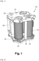
- This handle 20 can for example be formed by an opening made in the plate concerned, as in the particular embodiment of the figure 1 .
- the device 10 may also include at least one transport strap (not shown) which can pass through this opening.
- the handle 20 may be attached to one of the metal tubes 16, or several handles 20 may be attached to the metal tubes 16. Such a variant is also illustrated on the figure 1 .
- each cylinder 18 can be fixed on the plates 12 and 14 by means of a protuberance 22 of hemispherical shape present on each of the two plates 12 and 14.
- the cylinder 18 is hollow, has an equal internal diameter with the diameter of the protuberances 22, thus fits onto these protuberances 22 and is movable in rotation around them.
- the first and second plates 12, 14 have a generally square shape and the device 10 comprises three cylinders 18 respectively mounted in three angles of this generally square shape, the device 10 having in this embodiment handles 20 provided in the fourth angle of this generally square shape, including a handle 20 formed directly in the first plate 12 and a handle 20 attached to one of the metal tubes 16.
- the three cylinders 18 are arranged in a triangular manner on the square plates 12, 14.
- plates 12 and 14 of the embodiment of the figure 1 can have a thickness of 2 cm and a side length of 260 mm and the metal tubes 16 can have a length of 260 mm.
- the entire device 10 of the embodiment of the figure 1 is thus substantially cubic.
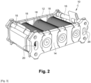
- FIG 2 shows another particular embodiment of the device 10, in which the first and second plates 12, 14 have a generally rectangular shape.
- the device 10 comprises at least three cylinders 18 mounted in an aligned manner along the longer sides of the generally rectangular shape.
- plates 12 and 14 of the embodiment of the figure 2 can have a thickness of 2 cm, a length of 400 mm and a width of 260 mm and the metal tubes 16 can have a length of 260 mm.
- the plates 12 and 14 can have a shape adapted to the horizontal and vertical stacking of several examples of the device 10. As shown in the figures 1 And 2 , this adapted shape can for example include small additional sides provided at each corner of the generally square shape or of the generally rectangular shape of the plates 12 and 14.
- the Figure 3 illustrates an example of horizontal stacking of two examples of the device 10 conforming to the particular embodiment of the figure 2 .
- the device 10 may further comprise a wire guide system (not shown) arranged on one of the metal tubes 16 and consisting for example of a rod fixed on the metal tube 16, this rod having at its end a thread guide eyelet.
- a wire guide system (not shown) arranged on one of the metal tubes 16 and consisting for example of a rod fixed on the metal tube 16, this rod having at its end a thread guide eyelet.
- the device 10 can further comprise an orifice 24 in the flat face of each of the hemispherical protuberances 22 and a key (not shown) of shape complementary to that of the orifice 24, adapted to be inserted therein to rotate the cylinder 18 and thus rewind the electrical wire or cable wound around this cylinder 18.
- the orifice 24 and the cross section of the key may have a hexagonal shape.
- the device 10 may further comprise, on the upper panel 14 and/or on the base panel 12, at least one wire hook eyelet 50 adapted to receive one end of the wire or cable wound on one of the cylinders 18.
Landscapes
- Storage Of Web-Like Or Filamentary Materials (AREA)
- Storing, Repeated Paying-Out, And Re-Storing Of Elongated Articles (AREA)
- Packaging Of Annular Or Rod-Shaped Articles, Wearing Apparel, Cassettes, Or The Like (AREA)
Priority Applications (1)
| Application Number | Priority Date | Filing Date | Title |
|---|---|---|---|
| EP26158805.7A EP4723409A2 (de) | 2022-04-19 | 2023-03-24 | Vorrichtung zum lagern, transportieren und installieren von elektrischen drähten und kabeln |
Applications Claiming Priority (1)
| Application Number | Priority Date | Filing Date | Title |
|---|---|---|---|
| FR2203599A FR3134664B1 (fr) | 2022-04-19 | 2022-04-19 | Dispositif de stockage, transport et installation de fils et câbles électriques |
Related Child Applications (2)
| Application Number | Title | Priority Date | Filing Date |
|---|---|---|---|
| EP26158805.7A Division-Into EP4723409A2 (de) | 2022-04-19 | 2023-03-24 | Vorrichtung zum lagern, transportieren und installieren von elektrischen drähten und kabeln |
| EP26158805.7A Division EP4723409A2 (de) | 2022-04-19 | 2023-03-24 | Vorrichtung zum lagern, transportieren und installieren von elektrischen drähten und kabeln |
Publications (2)
| Publication Number | Publication Date |
|---|---|
| EP4265550A1 true EP4265550A1 (de) | 2023-10-25 |
| EP4265550B1 EP4265550B1 (de) | 2026-05-06 |
Family
ID=82943024
Family Applications (2)
| Application Number | Title | Priority Date | Filing Date |
|---|---|---|---|
| EP26158805.7A Pending EP4723409A2 (de) | 2022-04-19 | 2023-03-24 | Vorrichtung zum lagern, transportieren und installieren von elektrischen drähten und kabeln |
| EP23164197.8A Active EP4265550B1 (de) | 2022-04-19 | 2023-03-24 | Vorrichtung zum lagern, transportieren und installieren von elektrischen drähten und kabeln |
Family Applications Before (1)
| Application Number | Title | Priority Date | Filing Date |
|---|---|---|---|
| EP26158805.7A Pending EP4723409A2 (de) | 2022-04-19 | 2023-03-24 | Vorrichtung zum lagern, transportieren und installieren von elektrischen drähten und kabeln |
Country Status (2)
| Country | Link |
|---|---|
| EP (2) | EP4723409A2 (de) |
| FR (1) | FR3134664B1 (de) |
Cited By (1)
| Publication number | Priority date | Publication date | Assignee | Title |
|---|---|---|---|---|
| WO2026062332A1 (fr) * | 2024-09-18 | 2026-03-26 | Nexans | Dispositif de stockage, transport et installation de fils et câbles électriques comportant un moyen d'empilement |
Citations (3)
| Publication number | Priority date | Publication date | Assignee | Title |
|---|---|---|---|---|
| WO1998042609A1 (fr) * | 1997-03-21 | 1998-10-01 | Murazumi Industrial Co., Ltd. | Plaque de fixation pour bobine ou produits analogues |
| EP2017211A1 (de) * | 2007-07-18 | 2009-01-21 | Nexans, Societe Anonyme | Vorrichtung zum Abwickeln von aufgewickelten Kabelrollen |
| US20110101148A1 (en) * | 2008-05-29 | 2011-05-05 | Adc Gmbh | Device for dispensing a telecommunication cable from a reel |
-
2022
- 2022-04-19 FR FR2203599A patent/FR3134664B1/fr active Active
-
2023
- 2023-03-24 EP EP26158805.7A patent/EP4723409A2/de active Pending
- 2023-03-24 EP EP23164197.8A patent/EP4265550B1/de active Active
Patent Citations (3)
| Publication number | Priority date | Publication date | Assignee | Title |
|---|---|---|---|---|
| WO1998042609A1 (fr) * | 1997-03-21 | 1998-10-01 | Murazumi Industrial Co., Ltd. | Plaque de fixation pour bobine ou produits analogues |
| EP2017211A1 (de) * | 2007-07-18 | 2009-01-21 | Nexans, Societe Anonyme | Vorrichtung zum Abwickeln von aufgewickelten Kabelrollen |
| US20110101148A1 (en) * | 2008-05-29 | 2011-05-05 | Adc Gmbh | Device for dispensing a telecommunication cable from a reel |
Cited By (1)
| Publication number | Priority date | Publication date | Assignee | Title |
|---|---|---|---|---|
| WO2026062332A1 (fr) * | 2024-09-18 | 2026-03-26 | Nexans | Dispositif de stockage, transport et installation de fils et câbles électriques comportant un moyen d'empilement |
Also Published As
| Publication number | Publication date |
|---|---|
| EP4265550B1 (de) | 2026-05-06 |
| FR3134664B1 (fr) | 2024-08-16 |
| EP4723409A2 (de) | 2026-04-08 |
| FR3134664A1 (fr) | 2023-10-20 |
Similar Documents
| Publication | Publication Date | Title |
|---|---|---|
| EP0978746B1 (de) | Verbindungsvorrichtung für faseroptische Kabel | |
| EP2861813B1 (de) | Batterieanordnung in der wickelwelle eines behangs | |
| EP1581830A1 (de) | Spule zur aufbewahrung mit vorrichtung zum abrollen von optischen kabeln | |
| EP4265550B1 (de) | Vorrichtung zum lagern, transportieren und installieren von elektrischen drähten und kabeln | |
| WO2008132416A1 (fr) | Perfectionnement aux bobines de grand diametre, pour la reception notamment d'un tube flexible ou d'un cable ombilical | |
| EP3378818A1 (de) | Draht wickel- und/oder abwickelvorrichtung | |
| EP2112113A1 (de) | Vorrichtung zum Lagern von Kabeln und Rohren | |
| FR2634305A1 (fr) | Appareil distributeur de produits plats a enroulements en helice rotatifs | |
| FR3132182A1 (fr) | Dispositif de stockage, transport et installation de fils et câbles électriques | |
| FR2698622A1 (fr) | Dérouleur de gaine flexible. | |
| EP0902997A1 (de) | Vorrichtung zum montieren wenigstens eines kabels in eine scheibe,welche zum positionieren in eine schutzmuffe einer kabelverbindung bestimmt ist | |
| EP3974363B1 (de) | Transportvorrichtung für eine kabelrolle mit einem richtrohr | |
| EP0115977B1 (de) | Aufwickelrohr für ein Segel und Vorrichtung zum Aufwickeln von Segeln versehen mit solch einem Rohr | |
| FR2866018A1 (fr) | Bobine de grand diametre pour la reception notamment d'un tube flexible ou d'un tube rigide roule | |
| EP1733989B1 (de) | Spule mit Handgriff | |
| WO2003024208A1 (fr) | Caisse de rangement et/ou de preparation de ligne palangre | |
| EP1834915A1 (de) | Metallwickelspule für Kabel, Schläuche oder Ähnliches | |
| EP1103509B1 (de) | Auf- und Abwickelvorrichtung für ein verlängertes flexibles Element | |
| EP0531274A1 (de) | Befestigungsvorrichtung für ein Tuch auf einem Wickelträger | |
| EP2331429B1 (de) | Schutzelement für ein zu schützendes glied, insbesondere einen abgasschlauch | |
| WO2026062332A1 (fr) | Dispositif de stockage, transport et installation de fils et câbles électriques comportant un moyen d'empilement | |
| EP4112520A1 (de) | Trommel für elektrokabel | |
| FR2837482A1 (fr) | Dispositif d'enroulement de cable | |
| EP3340407A1 (de) | Säule als halterung für mindestens ein elektrogerät und/oder den kabelkanal | |
| EP1240096B1 (de) | Abwickelvorrichtung für langgestrecktes gut zur inneren verdrahtung von gebäuden |
Legal Events
| Date | Code | Title | Description |
|---|---|---|---|
| STAA | Information on the status of an ep patent application or granted ep patent |
Free format text: STATUS: THE APPLICATION HAS BEEN PUBLISHED |
|
| PUAI | Public reference made under article 153(3) epc to a published international application that has entered the european phase |
Free format text: ORIGINAL CODE: 0009012 |
|
| AK | Designated contracting states |
Kind code of ref document: A1 Designated state(s): AL AT BE BG CH CY CZ DE DK EE ES FI FR GB GR HR HU IE IS IT LI LT LU LV MC ME MK MT NL NO PL PT RO RS SE SI SK SM TR |
|
| STAA | Information on the status of an ep patent application or granted ep patent |
Free format text: STATUS: REQUEST FOR EXAMINATION WAS MADE |
|
| 17P | Request for examination filed |
Effective date: 20240425 |
|
| RBV | Designated contracting states (corrected) |
Designated state(s): AL AT BE BG CH CY CZ DE DK EE ES FI FR GB GR HR HU IE IS IT LI LT LU LV MC ME MK MT NL NO PL PT RO RS SE SI SK SM TR |
|
| GRAP | Despatch of communication of intention to grant a patent |
Free format text: ORIGINAL CODE: EPIDOSNIGR1 |
|
| STAA | Information on the status of an ep patent application or granted ep patent |
Free format text: STATUS: GRANT OF PATENT IS INTENDED |
|
| RIC1 | Information provided on ipc code assigned before grant |
Ipc: B65H 49/20 20060101AFI20251103BHEP Ipc: B65H 49/32 20060101ALI20251103BHEP Ipc: B65H 49/36 20060101ALI20251103BHEP Ipc: B65H 49/38 20060101ALI20251103BHEP Ipc: H02G 11/02 20060101ALI20251103BHEP |
|
| INTG | Intention to grant announced |
Effective date: 20251121 |
|
| GRAS | Grant fee paid |
Free format text: ORIGINAL CODE: EPIDOSNIGR3 |
|
| GRAA | (expected) grant |
Free format text: ORIGINAL CODE: 0009210 |
|
| STAA | Information on the status of an ep patent application or granted ep patent |
Free format text: STATUS: THE PATENT HAS BEEN GRANTED |