EP4265581B1 - Verfahren zum behandeln von abgas aus einer zementanlage - Google Patents
Verfahren zum behandeln von abgas aus einer zementanlage Download PDFInfo
- Publication number
- EP4265581B1 EP4265581B1 EP22020183.4A EP22020183A EP4265581B1 EP 4265581 B1 EP4265581 B1 EP 4265581B1 EP 22020183 A EP22020183 A EP 22020183A EP 4265581 B1 EP4265581 B1 EP 4265581B1
- Authority
- EP
- European Patent Office
- Prior art keywords
- exhaust gas
- raw meal
- several
- gas
- cement
- Prior art date
- Legal status (The legal status is an assumption and is not a legal conclusion. Google has not performed a legal analysis and makes no representation as to the accuracy of the status listed.)
- Active
Links
Images
Classifications
-
- C—CHEMISTRY; METALLURGY
- C04—CEMENTS; CONCRETE; ARTIFICIAL STONE; CERAMICS; REFRACTORIES
- C04B—LIME, MAGNESIA; SLAG; CEMENTS; COMPOSITIONS THEREOF, e.g. MORTARS, CONCRETE OR LIKE BUILDING MATERIALS; ARTIFICIAL STONE; CERAMICS; REFRACTORIES; TREATMENT OF NATURAL STONE
- C04B7/00—Hydraulic cements
- C04B7/36—Manufacture of hydraulic cements in general
- C04B7/364—Avoiding environmental pollution during cement-manufacturing
- C04B7/367—Avoiding or minimising carbon dioxide emissions
-
- C—CHEMISTRY; METALLURGY
- C04—CEMENTS; CONCRETE; ARTIFICIAL STONE; CERAMICS; REFRACTORIES
- C04B—LIME, MAGNESIA; SLAG; CEMENTS; COMPOSITIONS THEREOF, e.g. MORTARS, CONCRETE OR LIKE BUILDING MATERIALS; ARTIFICIAL STONE; CERAMICS; REFRACTORIES; TREATMENT OF NATURAL STONE
- C04B7/00—Hydraulic cements
- C04B7/36—Manufacture of hydraulic cements in general
- C04B7/43—Heat treatment, e.g. precalcining, burning, melting; Cooling
- C04B7/432—Preheating without addition of fuel
-
- C—CHEMISTRY; METALLURGY
- C04—CEMENTS; CONCRETE; ARTIFICIAL STONE; CERAMICS; REFRACTORIES
- C04B—LIME, MAGNESIA; SLAG; CEMENTS; COMPOSITIONS THEREOF, e.g. MORTARS, CONCRETE OR LIKE BUILDING MATERIALS; ARTIFICIAL STONE; CERAMICS; REFRACTORIES; TREATMENT OF NATURAL STONE
- C04B7/00—Hydraulic cements
- C04B7/36—Manufacture of hydraulic cements in general
- C04B7/43—Heat treatment, e.g. precalcining, burning, melting; Cooling
- C04B7/436—Special arrangements for treating part or all of the cement kiln dust
-
- C—CHEMISTRY; METALLURGY
- C04—CEMENTS; CONCRETE; ARTIFICIAL STONE; CERAMICS; REFRACTORIES
- C04B—LIME, MAGNESIA; SLAG; CEMENTS; COMPOSITIONS THEREOF, e.g. MORTARS, CONCRETE OR LIKE BUILDING MATERIALS; ARTIFICIAL STONE; CERAMICS; REFRACTORIES; TREATMENT OF NATURAL STONE
- C04B7/00—Hydraulic cements
- C04B7/36—Manufacture of hydraulic cements in general
- C04B7/43—Heat treatment, e.g. precalcining, burning, melting; Cooling
- C04B7/47—Cooling ; Waste heat management
-
- Y—GENERAL TAGGING OF NEW TECHNOLOGICAL DEVELOPMENTS; GENERAL TAGGING OF CROSS-SECTIONAL TECHNOLOGIES SPANNING OVER SEVERAL SECTIONS OF THE IPC; TECHNICAL SUBJECTS COVERED BY FORMER USPC CROSS-REFERENCE ART COLLECTIONS [XRACs] AND DIGESTS
- Y02—TECHNOLOGIES OR APPLICATIONS FOR MITIGATION OR ADAPTATION AGAINST CLIMATE CHANGE
- Y02C—CAPTURE, STORAGE, SEQUESTRATION OR DISPOSAL OF GREENHOUSE GASES [GHG]
- Y02C20/00—Capture or disposal of greenhouse gases
- Y02C20/40—Capture or disposal of greenhouse gases of CO2
-
- Y—GENERAL TAGGING OF NEW TECHNOLOGICAL DEVELOPMENTS; GENERAL TAGGING OF CROSS-SECTIONAL TECHNOLOGIES SPANNING OVER SEVERAL SECTIONS OF THE IPC; TECHNICAL SUBJECTS COVERED BY FORMER USPC CROSS-REFERENCE ART COLLECTIONS [XRACs] AND DIGESTS
- Y02—TECHNOLOGIES OR APPLICATIONS FOR MITIGATION OR ADAPTATION AGAINST CLIMATE CHANGE
- Y02P—CLIMATE CHANGE MITIGATION TECHNOLOGIES IN THE PRODUCTION OR PROCESSING OF GOODS
- Y02P40/00—Technologies relating to the processing of minerals
- Y02P40/10—Production of cement, e.g. improving or optimising the production methods; Cement grinding
- Y02P40/18—Carbon capture and storage [CCS]
Definitions
- the invention relates to a method of processing exhaust gas from a cement plant, the cement plant comprising one or several raw meal mills for milling a cement raw meal, one or several preheater strings, each having a plurality of preheater stages, and a rotary kiln, wherein the one or several preheater strings are for preheating the cement raw meal in counter-current flow with an exhaust gas from the rotary kiln.
- the invention relates to a cement production unit for carrying out such a method, comprising:
- raw meal is fed into a calcination device, in particular a rotary kiln, after it has been preheated and partially decarbonated in a multistage preheater system by using the heat of combustion gases exhausted from the rotary kiln.
- the preheated raw material is fed into the rotary kiln via the kiln inlet and travels to the kiln outlet while being calcined at temperatures of up to 1400°C.
- the cement industry is an important emitter of CO 2 .
- significant amounts of CO 2 are generated during the decarbonation of raw meal (containing CaCO 3 ) to lime (CaO).
- CaO lime
- During the production of Portland cement clinker about 0,9 tons of CO 2 per ton of Portland cement clinker are emitted by the calcination of the raw materials and from the fuel combustion in the rotary kiln and the calciner.
- a known technology for capturing CO 2 present in flue gases is amine scrubbing, or other chemicals such as potassium carbonate. This process consists of extracting the CO 2 fraction from a post-combustion flue gas by flushing the gases with an amine solvent, regenerating the solvent by steam stripping, thus releasing nearly pure CO 2 , and recycling the stripped solvent to the absorber.
- amine scrubbing or other chemicals such as potassium carbonate. This process consists of extracting the CO 2 fraction from a post-combustion flue gas by flushing the gases with an amine solvent, regenerating the solvent by steam stripping, thus releasing nearly pure CO 2 , and recycling the stripped solvent to the absorber.
- CO 2 can be physically separated from a CO 2 containing gas by means of adsorbents, or membranes.
- CO 2 can be stored in different ways, such as, e.g., in stable carbonate mineral forms.
- the respective process is known as "carbon sequestration by mineral carbonation".
- the process involves reacting carbon dioxide with a carbonatable solid material, said material comprising metal oxides, in particular magnesium oxide (MgO) or calcium oxide (CaO), to form stable carbonates.
- MgO magnesium oxide
- CaO calcium oxide
- the CO 2 extracted can be used as feedstock to produce biofuels, other hydrocarbons, or sequestrated.
- JP 2008 239359 discloses a method of recovering carbon dioxide in a cement firing equipment that is provided with a step for cooling the waste gas from a suspension preheater, a step for eliminating steam in the suspension preheater waste gas using a gas cooling, moisture reducing and dust removing apparatus, a step for liquefying carbon dioxide in the suspension preheater waste gas using a carbon dioxide liquefaction apparatus and a step for circulating and utilizing a part of the suspension preheater waste gas as a cooling gas for a clinker cooler using a circulation line.
- This document describes cooling the exhaust gas in heat exchange with a water circulation line that is connected with a waste heat power generator that generates electricity.
- the instant invention aims at further reducing the CO 2 footprint of a cement plant and to increase the efficiency of CO 2 removal from the exhaust gas of a cement manufacturing plant.
- the invention provides a method of processing exhaust gas from a cement plant, wherein the method comprises:
- the invention is based on the idea to extract the exhaust gas from the cement plant at a considerable upstream distance from the exhaust gas stack. More specifically, the exhaust gas is taken from a downstream end region of the preheater string, i.e. from the second highest or highest stage of the preheater string, where the CO 2 content of the exhaust gas is substantially higher than at the exhaust stack. This is mainly due to the unavoidable amounts of false air ingress in the cement process between the preheater string and the exhaust gas stack, which dilutes the CO 2 in the exhaust gas.
- the CO 2 content of the exhaust gas is ⁇ 22 dry vol.-% at the exhaust stack, compared to 30-40 dry vol.-% directly after the preheater string. A high CO 2 content significantly increases the efficiency of the carbon capture process.
- the invention avoids extracting exhaust gas that has a disadvantageously high temperature, such as directly after the rotary kiln or from a lower stage of the preheater.
- extracting the exhaust gas from a lower stage of the preheater string would complicate the cooling step that is required for being able to process the exhaust gas in a carbon capture installation.
- the term "extracting exhaust gas from the second highest or highest stage of the preheater string” is understood to refer to the process of taking up to 100% of the exhaust gas that flows through the second highest and/or highest stage of the preheater string and guiding the exhaust gas to a subsequent installation. This comprises embodiments, in which the exhaust gas is extracted from between the highest stage and the second highest stage of the preheater string.
- the extraction of the exhaust gas may be realized as follows.
- the exhaust gas coming from the uppermost stage of the preheater string is guided through a kiln fan, is subsequently cooled in a conditioning tower and then introduced into the raw meal mill to dry cement raw meal.
- the extraction of the exhaust gas is carried out by installing a junction in the existing tubing so as to divert the exhaust gas from the existing tubing at the second highest stage or at a location downstream of the second highest stage of the preheater string, such as between the uppermost stage of the preheater and the kiln fan, or between the kiln fan and the raw meal mill.
- the exhaust gas may be extracted from any location between the second highest stage of the preheater string and the exhaust stack, as long as the extracted exhaust gas that is introduced into the carbon capture installation, has a CO 2 -content of > 25 vol.-%, preferably > 30 vol.-%.
- the invention provides that the CO 2 lean gas leaving the carbon capture installation is optionally introduced into the raw meal mill for using the sensible heat of the CO 2 lean gas to dry the cement raw meal.
- the drying of the raw meal with the CO 2 lean gas is particularly effective, since the CO 2 lean gas taken from the carbon capture installation is dry.
- the CO 2 lean gas after having been used in the raw meal mill to dry the raw meal, may advantageously be released into the atmosphere. Therefore, a preferred embodiment of the invention provides for a step of extracting the CO 2 lean gas from the raw meal mill and discharging it through an exhaust stack of the cement plant.
- the carbon capture installation used within the context of the instant invention may be any installation that is able to separate CO 2 from the CO 2 containing exhaust gas by any means known in the art, in order to provide a CO 2 lean gas.
- CO 2 lean gas shall not be understood to refer to the total absence of any CO 2 molecule.
- a CO 2 lean gas is understood to be a gas that contains less than 5 vol.% of CO 2 , preferably less than 3 vol.% of CO 2 .
- the carbon capture installation may further comprise a dedusting unit, and a gas cooler in order to treat the gas.
- the exhaust gas when being introduced into the carbon capture installation, has a CO 2 -content of > 25 vol.-%, preferably > 30 vol.-%, expressed as a volume percentage of the dry gas.
- the exhaust gas may have the following composition:
- the invention may also be used in a cement manufacturing plant that is operated in an oxygen enriched mode, also called oxyfuel mode.
- oxygen and recycled flue gas replace the conventional combustion air up to 100% in the calciner and/or the rotary kiln of the cement manufacturing plant, so as to directly generate an exhaust gas that has an increased CO 2 content, since nitrogen is not present any more as a diluent of the carbon dioxide produced. This further reduces the costs of separating CO 2 in the carbon capture installation.
- the entire flow of exhaust gas leaving the preheater string is subjected to the cooling and the dedusting steps and introduced into the carbon capture installation.
- only a partial flow of the exhaust gas leaving the preheater string is subjected to the cooling and dedusting steps and introduced into the carbon capture installation.
- the remaining flow of the exhaust gas leaving the preheater string will in this case be guided to the exhaust stack in accordance with the conventional plant layout, namely, in this sequence, via the kiln fan, the conditioning tower, the raw meal mill and the exhaust stack.
- the exhaust gas leaving the preheater string shall be cooled to a temperature of ⁇ 250°C, in order to be suitable for being processed in the carbon capture installation.
- the cooling step may preferably be configured to cool the exhaust gas leaving the preheater string to a temperature of ⁇ 150°C, such as to a temperature of approx. 140°C.
- the exhaust gas when entering the carbon capture installation has a temperature of ⁇ 250°C, preferably ⁇ 150°C.
- solid particles contained in the exhaust gas may be removed from the exhaust gas by use of a particle filter to produce a clean gas flow.
- the dedusting step may be arranged upstream of the cooling unit or downstream of the cooling unit, but in any case, upstream of the carbon capture installation.
- said step of cooling the exhaust gas comprises causing the exhaust gas to flow through a heat exchanger, in which the exhaust gas is cooled in heat exchange with the CO 2 lean gas that is being heated, preferably before being introduced into the raw meal mill. Therefore, the thermal energy retrieved from the exhaust gas during the cooling step is re-used to heat the CO 2 lean gas that is coming from the carbon capture installation to a temperature that is suitable for drying cement raw meal in the raw meal mill.
- the CO 2 lean gas is heated to a temperature of > 250°C.
- the heat exchanger is preferably designed as a waste heat recovery exchanger.
- the CO 2 lean gas may be subjected to an additional heating step before being introduced into the raw meal mill.
- Said additional heating may be carried out, e.g., in an electric heater.
- the additional heating step may be arranged upstream of the heat exchanger or preferably downstream of the heat exchanger.
- the heating requirement in the heat exchanger may vary depending on the set up of the cement plant and the humidity in the raw meal.
- the CO 2 lean gas may not be needed to dry the raw meal and could be evacuated to the stack.
- the CO 2 lean gas could be used without heating.
- the CO 2 lean gas is preferably heated in the heat exchanger, but no additional heating step is required to dry the raw meal.
- the clinker cooler waste air could be used to dry the raw meal.
- atmospheric air could be used in addition or in replacement of the CO 2 lean gas to cool down the exhaust gas. Therefore, the thermal energy recovered by the atmospheric air and optionally the CO 2 lean gas could be used to dry the raw meal.
- the invention refers to a cement production unit for carrying out a method according to the invention, wherein the device comprises:
- the cement production unit may further comprise one or several raw meal mills for milling a cement raw meal, wherein an outlet line of the carbon capture installation is connected to at least one of the one or several cement raw mills for introducing the CO 2 lean gas from the carbon capture installation into the at least one of the one or several raw meal mills.
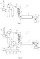
- Fig. 1 shows a layout of a cement plant as commonly used
- Fig. 2 shows a layout of a cement plant for carrying out the method of the invention.
- Fig. 1 schematically illustrates a cement plant, in which raw meal 2 is ground in a raw meal mill 3 and the ground raw meal is charged into a preheater string 4, where it is preheated in counter-current to the hot exhaust gases 9 coming from a rotary clinker kiln 5.
- the preheater string 4 comprises a plurality of interconnected preheaters, such as cyclone suspension-type preheaters.
- the preheated and optionally pre-calcined raw meal is then introduced into the rotary kiln 5, where it is calcined to obtain cement clinker.
- the clinker leaves the rotary kiln 5 and is cooled in a clinker cooler 6.
- the cooled clinker is charged into a cement mill 7, where the clinker is ground to a desired fineness, optionally together with other components of the final product, such as supplementary cementitious substances and gypsum.
- Fig. 1 the flow of solid material is shown with solid lines, while the flow of gas is shown with dotted lines.
- cooling air 8 is introduced into the clinker cooler 6, where the air is heated in heat exchange with the clinker.
- the heated air leaving the clinker cooler 6 is introduced into the rotary kiln 5, where the preheated raw meal is calcined, i.e. decarbonated, while releasing CO 2 .
- the CO 2 enriched exhaust gas 9 is introduced into the preheater string 4 in order to preheat the raw meal.
- the exhaust gas withdrawn from the preheater string 4 is introduced into a gas conditioning tower 10 via the kiln ID (induced draft) fan 15, where water may be injected in order to cool the exhaust gas.
- the cooled exhaust gas may be introduced into the raw meal mill 3 via the line 13 for preheating the raw meal and further cooling the exhaust gas.
- the exhaust gas leaving the raw meal mill is loaded with fine particles of raw meal and is introduced into the main filter 11 for separating said fine particles from the exhaust gas.
- the exhaust gas is withdrawn from the main filter 11 and directed through an exhaust stack 12.
- the cooled exhaust gas coming from the gas conditioning tower 10 is directly led to the main filter 11 via the line 14, where cement kiln dust entrained from rotary kiln 5 is separated from the exhaust gas.
- Fig. 2 shows a cement plant layout for carrying out the invention.
- the cement plant 1 of Fig. 1 has been adapted with respect to the exhaust gas that leaves the preheater 4 via the kiln ID fan 15.
- the exhaust gas taken from the uppermost stage of the preheater 4 is first cooled in a heat exchanger 16 to a temperature of ⁇ 180°C, and then introduced via line 17 and a filter 21 into a carbon capture installation 18, in which CO 2 is separated from the exhaust gas for obtaining an essentially CO 2 lean gas and substantially pure CO 2 19.
- the CO 2 lean gas is directed to the raw meal mill 3 via line 20 and the heat exchanger 16, and used in the raw meal mill 3 to dry the cement raw meal.
- the CO 2 lean gas is heated in heat exchange with the exhaust gas that comes from the preheater 4.
- the carbon capture installation 18 comprises a Direct Contact Cooler 22 to further cool down the exhaust gas and remove the minor impurities like acids (SOx, HCl, HF,...), a dryer 23, a CO 2 pre-concentrator 27, and a CO 2 purification unit 25.
- the CO 2 pre-concentrator may be configured to separate CO 2 from the exhaust gas by pressure swing adsorption (PSA), vacuum swing adsorption (VSA) or membranes.
- the CO 2 lean gas leaving the carbon capture installation 18 is a gas that contains substantially no CO 2 and no H 2 O. It substantially consists of N 2 and O 2 .
- an additional heater 26 may be installed upstream or downstream of the heat exchanger 16, in order to further increase the temperature of the CO 2 lean gas before introducing it into the raw meal mill 3.
Landscapes
- Chemical & Material Sciences (AREA)
- Engineering & Computer Science (AREA)
- Ceramic Engineering (AREA)
- Materials Engineering (AREA)
- Structural Engineering (AREA)
- Organic Chemistry (AREA)
- Physics & Mathematics (AREA)
- Thermal Sciences (AREA)
- Chemical Kinetics & Catalysis (AREA)
- Health & Medical Sciences (AREA)
- Life Sciences & Earth Sciences (AREA)
- Biodiversity & Conservation Biology (AREA)
- Ecology (AREA)
- Environmental & Geological Engineering (AREA)
- Environmental Sciences (AREA)
- Public Health (AREA)
- Treating Waste Gases (AREA)
- Waste-Gas Treatment And Other Accessory Devices For Furnaces (AREA)
Claims (10)
- Verfahren zur Verarbeitung von Abgas aus einem Zementwerk, wobei das Zementwerk eine oder mehrere Rohmehlmühlen zum Mahlen eines Zementrohmehls, einen oder mehrere Vorwärmstränge mit jeweils mehreren Vorwärmstufen und einen Drehrohrofen aufweist, wobei der eine oder die mehreren Vorwärmstränge zum Vorwärmen des Zementrohmehls im Gegenstrom mit einem Abgas aus dem Drehrohrofen dienen, wobei das Verfahren umfasst:- Entnahme des Abgases aus einer zweithöchsten oder höchsten Stufe von mindestens einem des einen oder der mehreren Vorwärmstränge,- Kühlung des Abgases auf eine Temperatur von < 250°C,- Entstaubung des Abgases,- Einleiten des gekühlten und entstaubten Abgases in eine Kohlenstoffabscheidungsanlage, in der CO2 aus dem Abgas abgetrennt wird, um ein CO2-armes Gas zu erhalten, wobei das Abgas beim Einleiten in die Kohlenstoffabscheidungsanlage einen CO2-Gehalt von > 25 Vol.-%, bevorzugt > 30 Vol.-% aufweist
wobei der Schritt der Kühlung des Abgases umfasst, dass das Abgas durch einen Wärmetauscher strömt, in dem das Abgas im Wärmeaustausch mit dem CO2-armen Gas, das erwärmt wird, gekühlt wird. - Verfahren nach Anspruch 1, ferner umfassend das Einleiten des CO2-armen Gases in mindestens eine der einen oder mehreren Rohmehlmühlen und die Verwendung des CO2-armen Gases in der mindestens einen der einen oder mehreren Rohmehlmühlen zur Trocknung des Zementrohmehls.
- Verfahren nach Anspruch 2, ferner umfassend die Entnahme des CO2-armen Gases aus mindestens einer der einen oder mehreren Rohmehlmühlen und Ableiten über einen Abgaskamin des Zementwerks.
- Verfahren nach Anspruch 1, 2 oder 3, wobei der gesamte Abgasstrom, der den mindestens einen der einen oder mehreren Vorwärmstränge verlässt, dem Kühlschritt unterzogen und in die Kohlenstoffabscheidungsanlage eingeleitet wird.
- Verfahren nach einem der Ansprüche 1 bis 4, wobei das CO2-arme Gas nach Erwärmung im Wärmetauscher in mindestens eine der einen oder mehreren Rohmehlmühlen eingeleitet wird.
- Verfahren nach Anspruch 5, wobei das CO2-arme Gas vor der Einleitung in die mindestens eine der einen oder mehreren Rohmehlmühlen einem zusätzlichen Erwärmungsschritt unterzogen wird.
- Zementherstellungsanlage zur Durchführung eines Verfahrens nach einem der Ansprüche 1 bis 6, umfassend:- einen oder mehrere Vorwärmstränge zum Vorwärmen von Zementrohmehl, wobei jeder Vorwärmstrang mehrere Vorwärmstufen aufweist,- einen Drehrohrofen und gegebenenfalls einen Vorkalzinator zum Kalzinieren des vorgewärmten Zementrohmehls und zur Gewinnung von Zementklinker,- eine Kühleinheit, eine Entstaubungseinheit und eine Kohlenstoffabscheidungsanlage, die mit mindestens einem der einen oder mehreren Vorwärmstränge verbunden sind, um Abgas aus einer zweithöchsten oder höchsten Stufe des mindestens einen der einen oder mehreren Vorwärmstränge abzuleiten, das Abgas zu kühlen und zu entstauben und das gekühlte und entstaubte Abgas in die Kohlenstoffabscheidungsanlage einzuleiten, in der CO2 aus dem Abgas abgetrennt wird, um ein CO2-armes Gas zu erhalten, wobei die Kühleinheit als Wärmetauscher ausgebildet ist, in dem das Abgas im Wärmeaustausch mit dem erwärmten CO2-armen Gas gekühlt wird.
- Zementherstellungsanlage nach Anspruch 7, ferner umfassend eine oder mehrere Rohmehlmühlen zum Mahlen von Zementrohmehl, wobei eine Auslassleitung der Kohlenstoffabscheidungsanlage mit mindestens einer der einen oder mehreren Zementrohmehlmühlen verbunden ist, um das CO2-arme Gas aus der Kohlenstoffabscheidungsanlage in die mindestens eine der einen oder mehreren Rohmehlmühlen einzuleiten.
- Zementherstellungsanlage nach Anspruch 7 oder 8, wobei das CO2-arme Gas nach dem Erwärmen in die mindestens eine der einen oder mehreren Rohmehlmühlen eingeleitet wird.
- Zementherstellungsanlage nach Anspruch 9, wobei ein zusätzlicher Wärmetauscher zur Erwärmung des CO2-armen Gases vor der Einleitung in die mindestens eine der einen oder mehreren Rohmehlmühlen vorgesehen ist.
Priority Applications (8)
| Application Number | Priority Date | Filing Date | Title |
|---|---|---|---|
| HRP20250967TT HRP20250967T1 (hr) | 2022-04-20 | 2022-04-20 | Postupak obrade ispušnog plina iz cementare |
| ES22020183T ES3037600T3 (en) | 2022-04-20 | 2022-04-20 | Method of processing exhaust gas from a cement plant |
| EP22020183.4A EP4265581B1 (de) | 2022-04-20 | 2022-04-20 | Verfahren zum behandeln von abgas aus einer zementanlage |
| PL22020183.4T PL4265581T3 (pl) | 2022-04-20 | 2022-04-20 | Sposób przetwarzania gazów spalinowych z cementowni |
| CN202380035025.2A CN119053567A (zh) | 2022-04-20 | 2023-04-19 | 处理来自水泥厂的废气的方法 |
| PCT/IB2023/053996 WO2023203502A1 (en) | 2022-04-20 | 2023-04-19 | Method of processing exhaust gas from a cement plant |
| CA3249337A CA3249337A1 (en) | 2022-04-20 | 2023-04-19 | PROCESS FOR TREATMENT OF EXHAUST GAS FROM A CEMENT PLANT |
| US18/857,647 US20250263336A1 (en) | 2022-04-20 | 2023-04-19 | Method of processing exhaust gas from a cement plant |
Applications Claiming Priority (1)
| Application Number | Priority Date | Filing Date | Title |
|---|---|---|---|
| EP22020183.4A EP4265581B1 (de) | 2022-04-20 | 2022-04-20 | Verfahren zum behandeln von abgas aus einer zementanlage |
Publications (2)
| Publication Number | Publication Date |
|---|---|
| EP4265581A1 EP4265581A1 (de) | 2023-10-25 |
| EP4265581B1 true EP4265581B1 (de) | 2025-06-04 |
Family
ID=81344445
Family Applications (1)
| Application Number | Title | Priority Date | Filing Date |
|---|---|---|---|
| EP22020183.4A Active EP4265581B1 (de) | 2022-04-20 | 2022-04-20 | Verfahren zum behandeln von abgas aus einer zementanlage |
Country Status (8)
| Country | Link |
|---|---|
| US (1) | US20250263336A1 (de) |
| EP (1) | EP4265581B1 (de) |
| CN (1) | CN119053567A (de) |
| CA (1) | CA3249337A1 (de) |
| ES (1) | ES3037600T3 (de) |
| HR (1) | HRP20250967T1 (de) |
| PL (1) | PL4265581T3 (de) |
| WO (1) | WO2023203502A1 (de) |
Family Cites Families (2)
| Publication number | Priority date | Publication date | Assignee | Title |
|---|---|---|---|---|
| JP4350765B2 (ja) * | 2007-03-26 | 2009-10-21 | 住友大阪セメント株式会社 | セメント焼成設備の二酸化炭素の回収方法及び回収装置 |
| CN107019991B (zh) * | 2017-04-17 | 2020-02-14 | 中国科学院过程工程研究所 | 一种工业烟气中co2富集以及余热回收系统和方法 |
-
2022
- 2022-04-20 ES ES22020183T patent/ES3037600T3/es active Active
- 2022-04-20 PL PL22020183.4T patent/PL4265581T3/pl unknown
- 2022-04-20 EP EP22020183.4A patent/EP4265581B1/de active Active
- 2022-04-20 HR HRP20250967TT patent/HRP20250967T1/hr unknown
-
2023
- 2023-04-19 US US18/857,647 patent/US20250263336A1/en active Pending
- 2023-04-19 CA CA3249337A patent/CA3249337A1/en active Pending
- 2023-04-19 CN CN202380035025.2A patent/CN119053567A/zh active Pending
- 2023-04-19 WO PCT/IB2023/053996 patent/WO2023203502A1/en not_active Ceased
Also Published As
| Publication number | Publication date |
|---|---|
| WO2023203502A1 (en) | 2023-10-26 |
| US20250263336A1 (en) | 2025-08-21 |
| CA3249337A1 (en) | 2023-10-26 |
| ES3037600T3 (en) | 2025-10-03 |
| EP4265581A1 (de) | 2023-10-25 |
| HRP20250967T1 (hr) | 2025-10-10 |
| CN119053567A (zh) | 2024-11-29 |
| PL4265581T3 (pl) | 2025-09-22 |
Similar Documents
| Publication | Publication Date | Title |
|---|---|---|
| KR20220005074A (ko) | 탄소 포집을 위한 시스템 및 방법 | |
| US11608294B2 (en) | Oxy-calcination process | |
| EP2559472A1 (de) | Integrierte Kohlendioxidabscheidung für Zementwerke | |
| EP4259591B1 (de) | Verfahren zur herstellung von klinkerformzementrohmehl | |
| KR20090097852A (ko) | Co2 방출이 제어되는 클링커 제조 방법 | |
| US20250026683A1 (en) | Cement manufacturing plant and method of operating a cement manufacturing plant | |
| WO2024008350A1 (en) | Method for manufacturing cement clinker and cement plant | |
| EP4265581B1 (de) | Verfahren zum behandeln von abgas aus einer zementanlage | |
| WO2013105070A1 (en) | Method and system for low emission co2 capture | |
| WO1999042416A1 (en) | Removal of sulfur oxides from preheater off gases | |
| CN114459236A (zh) | 一种大幅节能的水泥窑烟气碳捕集方法 | |
| WO2026027581A1 (en) | Decarbonation process of carbonated materials | |
| KR20260034653A (ko) | 상이한 조성을 갖는 적어도 두 개의 스트림으로부터 co2를 분리하는 방법 및 장치 | |
| KR20260040223A (ko) | 상이한 조성을 갖는 적어도 두 개의 스트림으로부터 co2를 분리하는 방법 및 장치 | |
| JP2024111494A (ja) | 二酸化炭素の回収システム | |
| WO2025078986A1 (en) | Method for clinker manufacturing with energy efficient carbon dioxide preservation | |
| TW201350190A (zh) | 用於低排放二氧化碳捕獲之裝置及系統 |
Legal Events
| Date | Code | Title | Description |
|---|---|---|---|
| REG | Reference to a national code |
Ref country code: HR Ref legal event code: TUEP Ref document number: P20250967T Country of ref document: HR |
|
| STAA | Information on the status of an ep patent application or granted ep patent |
Free format text: STATUS: THE APPLICATION HAS BEEN PUBLISHED |
|
| PUAI | Public reference made under article 153(3) epc to a published international application that has entered the european phase |
Free format text: ORIGINAL CODE: 0009012 |
|
| AK | Designated contracting states |
Kind code of ref document: A1 Designated state(s): AL AT BE BG CH CY CZ DE DK EE ES FI FR GB GR HR HU IE IS IT LI LT LU LV MC MK MT NL NO PL PT RO RS SE SI SK SM TR |
|
| STAA | Information on the status of an ep patent application or granted ep patent |
Free format text: STATUS: REQUEST FOR EXAMINATION WAS MADE |
|
| 17P | Request for examination filed |
Effective date: 20240424 |
|
| RBV | Designated contracting states (corrected) |
Designated state(s): AL AT BE BG CH CY CZ DE DK EE ES FI FR GB GR HR HU IE IS IT LI LT LU LV MC MK MT NL NO PL PT RO RS SE SI SK SM TR |
|
| GRAP | Despatch of communication of intention to grant a patent |
Free format text: ORIGINAL CODE: EPIDOSNIGR1 |
|
| STAA | Information on the status of an ep patent application or granted ep patent |
Free format text: STATUS: GRANT OF PATENT IS INTENDED |
|
| INTG | Intention to grant announced |
Effective date: 20250127 |
|
| GRAS | Grant fee paid |
Free format text: ORIGINAL CODE: EPIDOSNIGR3 |
|
| GRAA | (expected) grant |
Free format text: ORIGINAL CODE: 0009210 |
|
| STAA | Information on the status of an ep patent application or granted ep patent |
Free format text: STATUS: THE PATENT HAS BEEN GRANTED |
|
| AK | Designated contracting states |
Kind code of ref document: B1 Designated state(s): AL AT BE BG CH CY CZ DE DK EE ES FI FR GB GR HR HU IE IS IT LI LT LU LV MC MK MT NL NO PL PT RO RS SE SI SK SM TR |
|
| REG | Reference to a national code |
Ref country code: GB Ref legal event code: FG4D |
|
| REG | Reference to a national code |
Ref country code: CH Ref legal event code: EP |
|
| REG | Reference to a national code |
Ref country code: DE Ref legal event code: R096 Ref document number: 602022015311 Country of ref document: DE |
|
| REG | Reference to a national code |
Ref country code: IE Ref legal event code: FG4D |
|
| REG | Reference to a national code |
Ref country code: ES Ref legal event code: FG2A Ref document number: 3037600 Country of ref document: ES Kind code of ref document: T3 Effective date: 20251003 |
|
| REG | Reference to a national code |
Ref country code: NL Ref legal event code: MP Effective date: 20250604 |
|
| PG25 | Lapsed in a contracting state [announced via postgrant information from national office to epo] |
Ref country code: FI Free format text: LAPSE BECAUSE OF FAILURE TO SUBMIT A TRANSLATION OF THE DESCRIPTION OR TO PAY THE FEE WITHIN THE PRESCRIBED TIME-LIMIT Effective date: 20250604 |
|
| REG | Reference to a national code |
Ref country code: LT Ref legal event code: MG9D Ref country code: HR Ref legal event code: T1PR Ref document number: P20250967 Country of ref document: HR |
|
| PG25 | Lapsed in a contracting state [announced via postgrant information from national office to epo] |
Ref country code: NO Free format text: LAPSE BECAUSE OF FAILURE TO SUBMIT A TRANSLATION OF THE DESCRIPTION OR TO PAY THE FEE WITHIN THE PRESCRIBED TIME-LIMIT Effective date: 20250904 |
|
| P01 | Opt-out of the competence of the unified patent court (upc) registered |
Free format text: CASE NUMBER: UPC_APP_5971_4265581/2025 Effective date: 20250904 |
|
| PG25 | Lapsed in a contracting state [announced via postgrant information from national office to epo] |
Ref country code: BG Free format text: LAPSE BECAUSE OF FAILURE TO SUBMIT A TRANSLATION OF THE DESCRIPTION OR TO PAY THE FEE WITHIN THE PRESCRIBED TIME-LIMIT Effective date: 20250604 |
|
| PG25 | Lapsed in a contracting state [announced via postgrant information from national office to epo] |
Ref country code: RS Free format text: LAPSE BECAUSE OF FAILURE TO SUBMIT A TRANSLATION OF THE DESCRIPTION OR TO PAY THE FEE WITHIN THE PRESCRIBED TIME-LIMIT Effective date: 20250904 |
|
| PG25 | Lapsed in a contracting state [announced via postgrant information from national office to epo] |
Ref country code: LV Free format text: LAPSE BECAUSE OF FAILURE TO SUBMIT A TRANSLATION OF THE DESCRIPTION OR TO PAY THE FEE WITHIN THE PRESCRIBED TIME-LIMIT Effective date: 20250604 |
|
| REG | Reference to a national code |
Ref country code: GR Ref legal event code: EP Ref document number: 20250401733 Country of ref document: GR Effective date: 20251009 |
|
| PG25 | Lapsed in a contracting state [announced via postgrant information from national office to epo] |
Ref country code: NL Free format text: LAPSE BECAUSE OF FAILURE TO SUBMIT A TRANSLATION OF THE DESCRIPTION OR TO PAY THE FEE WITHIN THE PRESCRIBED TIME-LIMIT Effective date: 20250604 |
|
| PG25 | Lapsed in a contracting state [announced via postgrant information from national office to epo] |
Ref country code: PT Free format text: LAPSE BECAUSE OF FAILURE TO SUBMIT A TRANSLATION OF THE DESCRIPTION OR TO PAY THE FEE WITHIN THE PRESCRIBED TIME-LIMIT Effective date: 20251006 |
|
| REG | Reference to a national code |
Ref country code: AT Ref legal event code: MK05 Ref document number: 1800248 Country of ref document: AT Kind code of ref document: T Effective date: 20250604 |
|
| PG25 | Lapsed in a contracting state [announced via postgrant information from national office to epo] |
Ref country code: IS Free format text: LAPSE BECAUSE OF FAILURE TO SUBMIT A TRANSLATION OF THE DESCRIPTION OR TO PAY THE FEE WITHIN THE PRESCRIBED TIME-LIMIT Effective date: 20251004 |
|
| PG25 | Lapsed in a contracting state [announced via postgrant information from national office to epo] |
Ref country code: SM Free format text: LAPSE BECAUSE OF FAILURE TO SUBMIT A TRANSLATION OF THE DESCRIPTION OR TO PAY THE FEE WITHIN THE PRESCRIBED TIME-LIMIT Effective date: 20250604 Ref country code: AT Free format text: LAPSE BECAUSE OF FAILURE TO SUBMIT A TRANSLATION OF THE DESCRIPTION OR TO PAY THE FEE WITHIN THE PRESCRIBED TIME-LIMIT Effective date: 20250604 |
|
| PG25 | Lapsed in a contracting state [announced via postgrant information from national office to epo] |
Ref country code: CZ Free format text: LAPSE BECAUSE OF FAILURE TO SUBMIT A TRANSLATION OF THE DESCRIPTION OR TO PAY THE FEE WITHIN THE PRESCRIBED TIME-LIMIT Effective date: 20250604 |
|
| PG25 | Lapsed in a contracting state [announced via postgrant information from national office to epo] |
Ref country code: EE Free format text: LAPSE BECAUSE OF FAILURE TO SUBMIT A TRANSLATION OF THE DESCRIPTION OR TO PAY THE FEE WITHIN THE PRESCRIBED TIME-LIMIT Effective date: 20250604 |
|
| PG25 | Lapsed in a contracting state [announced via postgrant information from national office to epo] |
Ref country code: SK Free format text: LAPSE BECAUSE OF FAILURE TO SUBMIT A TRANSLATION OF THE DESCRIPTION OR TO PAY THE FEE WITHIN THE PRESCRIBED TIME-LIMIT Effective date: 20250604 |
|
| PG25 | Lapsed in a contracting state [announced via postgrant information from national office to epo] |
Ref country code: IT Free format text: LAPSE BECAUSE OF FAILURE TO SUBMIT A TRANSLATION OF THE DESCRIPTION OR TO PAY THE FEE WITHIN THE PRESCRIBED TIME-LIMIT Effective date: 20250604 |
|
| REG | Reference to a national code |
Ref country code: DE Ref legal event code: R097 Ref document number: 602022015311 Country of ref document: DE |
|
| PLBE | No opposition filed within time limit |
Free format text: ORIGINAL CODE: 0009261 |
|
| STAA | Information on the status of an ep patent application or granted ep patent |
Free format text: STATUS: NO OPPOSITION FILED WITHIN TIME LIMIT |
|
| PG25 | Lapsed in a contracting state [announced via postgrant information from national office to epo] |
Ref country code: DK Free format text: LAPSE BECAUSE OF FAILURE TO SUBMIT A TRANSLATION OF THE DESCRIPTION OR TO PAY THE FEE WITHIN THE PRESCRIBED TIME-LIMIT Effective date: 20250604 |
|
| VS25 | Lapsed in a validation state [announced via postgrant information from nat. office to epo] |
Ref country code: MA Free format text: LAPSE BECAUSE OF FAILURE TO SUBMIT A TRANSLATION OF THE DESCRIPTION OR TO PAY THE FEE WITHIN THE PRESCRIBED TIME-LIMIT Effective date: 20250604 |
|
| REG | Reference to a national code |
Ref country code: CH Ref legal event code: L10 Free format text: ST27 STATUS EVENT CODE: U-0-0-L10-L00 (AS PROVIDED BY THE NATIONAL OFFICE) Effective date: 20260416 |