EP4265850A1 - Baumaschine - Google Patents
Baumaschine Download PDFInfo
- Publication number
- EP4265850A1 EP4265850A1 EP21906734.5A EP21906734A EP4265850A1 EP 4265850 A1 EP4265850 A1 EP 4265850A1 EP 21906734 A EP21906734 A EP 21906734A EP 4265850 A1 EP4265850 A1 EP 4265850A1
- Authority
- EP
- European Patent Office
- Prior art keywords
- manipulation
- construction machine
- lever
- blade
- machine according
- Prior art date
- Legal status (The legal status is an assumption and is not a legal conclusion. Google has not performed a legal analysis and makes no representation as to the accuracy of the status listed.)
- Pending
Links
Images


Classifications
-
- E—FIXED CONSTRUCTIONS
- E02—HYDRAULIC ENGINEERING; FOUNDATIONS; SOIL SHIFTING
- E02F—DREDGING; SOIL-SHIFTING
- E02F9/00—Component parts of dredgers or soil-shifting machines, not restricted to one of the kinds covered by groups E02F3/00 - E02F7/00
- E02F9/20—Drives; Control devices
- E02F9/2004—Control mechanisms, e.g. control levers
-
- E—FIXED CONSTRUCTIONS
- E02—HYDRAULIC ENGINEERING; FOUNDATIONS; SOIL SHIFTING
- E02F—DREDGING; SOIL-SHIFTING
- E02F3/00—Dredgers; Soil-shifting machines
- E02F3/04—Dredgers; Soil-shifting machines mechanically-driven
- E02F3/28—Dredgers; Soil-shifting machines mechanically-driven with digging tools mounted on a dipper- or bucket-arm, i.e. there is either one arm or a pair of arms, e.g. dippers, buckets
- E02F3/30—Dredgers; Soil-shifting machines mechanically-driven with digging tools mounted on a dipper- or bucket-arm, i.e. there is either one arm or a pair of arms, e.g. dippers, buckets with a dipper-arm pivoted on a cantilever beam, i.e. boom
- E02F3/32—Dredgers; Soil-shifting machines mechanically-driven with digging tools mounted on a dipper- or bucket-arm, i.e. there is either one arm or a pair of arms, e.g. dippers, buckets with a dipper-arm pivoted on a cantilever beam, i.e. boom working downwardly and towards the machine, e.g. with backhoes
- E02F3/325—Backhoes of the miniature type
-
- E—FIXED CONSTRUCTIONS
- E02—HYDRAULIC ENGINEERING; FOUNDATIONS; SOIL SHIFTING
- E02F—DREDGING; SOIL-SHIFTING
- E02F3/00—Dredgers; Soil-shifting machines
- E02F3/04—Dredgers; Soil-shifting machines mechanically-driven
- E02F3/76—Graders, bulldozers, or the like with scraper plates or ploughshare-like elements; Levelling scarifying devices
- E02F3/80—Component parts
- E02F3/815—Blades; Levelling or scarifying tools
-
- E—FIXED CONSTRUCTIONS
- E02—HYDRAULIC ENGINEERING; FOUNDATIONS; SOIL SHIFTING
- E02F—DREDGING; SOIL-SHIFTING
- E02F3/00—Dredgers; Soil-shifting machines
- E02F3/04—Dredgers; Soil-shifting machines mechanically-driven
- E02F3/76—Graders, bulldozers, or the like with scraper plates or ploughshare-like elements; Levelling scarifying devices
- E02F3/7609—Scraper blade mounted forwardly of the tractor on a pair of pivoting arms which are linked to the sides of the tractor, e.g. bulldozers
- E02F3/7613—Scraper blade mounted forwardly of the tractor on a pair of pivoting arms which are linked to the sides of the tractor, e.g. bulldozers with the scraper blade adjustable relative to the pivoting arms about a vertical axis, e.g. angle dozers
-
- E—FIXED CONSTRUCTIONS
- E02—HYDRAULIC ENGINEERING; FOUNDATIONS; SOIL SHIFTING
- E02F—DREDGING; SOIL-SHIFTING
- E02F3/00—Dredgers; Soil-shifting machines
- E02F3/04—Dredgers; Soil-shifting machines mechanically-driven
- E02F3/76—Graders, bulldozers, or the like with scraper plates or ploughshare-like elements; Levelling scarifying devices
- E02F3/7609—Scraper blade mounted forwardly of the tractor on a pair of pivoting arms which are linked to the sides of the tractor, e.g. bulldozers
- E02F3/7618—Scraper blade mounted forwardly of the tractor on a pair of pivoting arms which are linked to the sides of the tractor, e.g. bulldozers with the scraper blade adjustable relative to the pivoting arms about a horizontal axis
-
- E—FIXED CONSTRUCTIONS
- E02—HYDRAULIC ENGINEERING; FOUNDATIONS; SOIL SHIFTING
- E02F—DREDGING; SOIL-SHIFTING
- E02F3/00—Dredgers; Soil-shifting machines
- E02F3/04—Dredgers; Soil-shifting machines mechanically-driven
- E02F3/96—Dredgers; Soil-shifting machines mechanically-driven with arrangements for alternate or simultaneous use of different digging elements
- E02F3/963—Arrangements on backhoes for alternate use of different tools
- E02F3/964—Arrangements on backhoes for alternate use of different tools of several tools mounted on one machine
-
- E—FIXED CONSTRUCTIONS
- E02—HYDRAULIC ENGINEERING; FOUNDATIONS; SOIL SHIFTING
- E02F—DREDGING; SOIL-SHIFTING
- E02F9/00—Component parts of dredgers or soil-shifting machines, not restricted to one of the kinds covered by groups E02F3/00 - E02F7/00
- E02F9/20—Drives; Control devices
-
- E—FIXED CONSTRUCTIONS
- E02—HYDRAULIC ENGINEERING; FOUNDATIONS; SOIL SHIFTING
- E02F—DREDGING; SOIL-SHIFTING
- E02F9/00—Component parts of dredgers or soil-shifting machines, not restricted to one of the kinds covered by groups E02F3/00 - E02F7/00
- E02F9/20—Drives; Control devices
- E02F9/2004—Control mechanisms, e.g. control levers
- E02F9/2012—Setting the functions of the control levers, e.g. changing assigned functions among operations levers, setting functions dependent on the operator or seat orientation
-
- G—PHYSICS
- G05—CONTROLLING; REGULATING
- G05G—CONTROL DEVICES OR SYSTEMS INSOFAR AS CHARACTERISED BY MECHANICAL FEATURES ONLY
- G05G1/00—Controlling members, e.g. knobs or handles; Assemblies or arrangements thereof; Indicating position of controlling members
- G05G1/02—Controlling members for hand actuation by linear movement, e.g. push buttons
-
- G—PHYSICS
- G05—CONTROLLING; REGULATING
- G05G—CONTROL DEVICES OR SYSTEMS INSOFAR AS CHARACTERISED BY MECHANICAL FEATURES ONLY
- G05G1/00—Controlling members, e.g. knobs or handles; Assemblies or arrangements thereof; Indicating position of controlling members
- G05G1/04—Controlling members for hand actuation by pivoting movement, e.g. levers
- G05G1/06—Details of their grip parts
-
- G—PHYSICS
- G05—CONTROLLING; REGULATING
- G05G—CONTROL DEVICES OR SYSTEMS INSOFAR AS CHARACTERISED BY MECHANICAL FEATURES ONLY
- G05G9/00—Manually-actuated control mechanisms provided with one single controlling member co-operating with two or more controlled members, e.g. selectively, simultaneously
- G05G9/02—Manually-actuated control mechanisms provided with one single controlling member co-operating with two or more controlled members, e.g. selectively, simultaneously the controlling member being movable in different independent ways, movement in each individual way actuating one controlled member only
- G05G9/04—Manually-actuated control mechanisms provided with one single controlling member co-operating with two or more controlled members, e.g. selectively, simultaneously the controlling member being movable in different independent ways, movement in each individual way actuating one controlled member only in which movement in two or more ways can occur simultaneously
- G05G9/047—Manually-actuated control mechanisms provided with one single controlling member co-operating with two or more controlled members, e.g. selectively, simultaneously the controlling member being movable in different independent ways, movement in each individual way actuating one controlled member only in which movement in two or more ways can occur simultaneously the controlling member being movable by hand about orthogonal axes, e.g. joysticks
-
- E—FIXED CONSTRUCTIONS
- E02—HYDRAULIC ENGINEERING; FOUNDATIONS; SOIL SHIFTING
- E02F—DREDGING; SOIL-SHIFTING
- E02F9/00—Component parts of dredgers or soil-shifting machines, not restricted to one of the kinds covered by groups E02F3/00 - E02F7/00
- E02F9/20—Drives; Control devices
- E02F9/22—Hydraulic or pneumatic drives
- E02F9/2203—Arrangements for controlling the attitude of actuators, e.g. speed, floating function
-
- E—FIXED CONSTRUCTIONS
- E02—HYDRAULIC ENGINEERING; FOUNDATIONS; SOIL SHIFTING
- E02F—DREDGING; SOIL-SHIFTING
- E02F9/00—Component parts of dredgers or soil-shifting machines, not restricted to one of the kinds covered by groups E02F3/00 - E02F7/00
- E02F9/20—Drives; Control devices
- E02F9/22—Hydraulic or pneumatic drives
- E02F9/2278—Hydraulic circuits
- E02F9/2285—Pilot-operated systems
-
- E—FIXED CONSTRUCTIONS
- E02—HYDRAULIC ENGINEERING; FOUNDATIONS; SOIL SHIFTING
- E02F—DREDGING; SOIL-SHIFTING
- E02F9/00—Component parts of dredgers or soil-shifting machines, not restricted to one of the kinds covered by groups E02F3/00 - E02F7/00
- E02F9/20—Drives; Control devices
- E02F9/22—Hydraulic or pneumatic drives
- E02F9/2278—Hydraulic circuits
- E02F9/2292—Systems with two or more pumps
-
- G—PHYSICS
- G05—CONTROLLING; REGULATING
- G05G—CONTROL DEVICES OR SYSTEMS INSOFAR AS CHARACTERISED BY MECHANICAL FEATURES ONLY
- G05G9/00—Manually-actuated control mechanisms provided with one single controlling member co-operating with two or more controlled members, e.g. selectively, simultaneously
- G05G9/02—Manually-actuated control mechanisms provided with one single controlling member co-operating with two or more controlled members, e.g. selectively, simultaneously the controlling member being movable in different independent ways, movement in each individual way actuating one controlled member only
- G05G9/04—Manually-actuated control mechanisms provided with one single controlling member co-operating with two or more controlled members, e.g. selectively, simultaneously the controlling member being movable in different independent ways, movement in each individual way actuating one controlled member only in which movement in two or more ways can occur simultaneously
- G05G9/047—Manually-actuated control mechanisms provided with one single controlling member co-operating with two or more controlled members, e.g. selectively, simultaneously the controlling member being movable in different independent ways, movement in each individual way actuating one controlled member only in which movement in two or more ways can occur simultaneously the controlling member being movable by hand about orthogonal axes, e.g. joysticks
- G05G2009/04774—Manually-actuated control mechanisms provided with one single controlling member co-operating with two or more controlled members, e.g. selectively, simultaneously the controlling member being movable in different independent ways, movement in each individual way actuating one controlled member only in which movement in two or more ways can occur simultaneously the controlling member being movable by hand about orthogonal axes, e.g. joysticks with additional switches or sensors on the handle
Definitions
- the present invention relates to a construction machine.
- the working machine of Patent Literature 1 has a blade provided on a lower traveling body thereof so as to be capable of performing an elevating operation, an angular operation, and a tilting operation.
- a blade lever is tilted in a forward and backward direction to lift the blade. Additionally, the blade lever is tilted in a left and right direction to cause the blade lever to perform the tilting operation and the angular operation. Switching between the tilting operation and the angular operation is performed using a button switch at a distal end of the blade lever.
- Patent Literature 1 Japanese Patent Laid-Open Publication No. 2005-207196
- the tilting operation and the angular operation mean tilting of the blade lever in the left and right direction, and the operations are common.
- the tilting operation is intended to be performed, but the angular operation may be performed by mistake.
- the present invention has been made in light of the above-mentioned problem, and the object is to provide a construction machine capable of suppressing occurrences of malfunctions.
- a construction machine is provided with a blade and a manipulation lever.
- the blade is provided on a machine body.
- the blade is configured to be capable of performing a plurality of operations.
- the manipulation lever manipulates the blade.
- the manipulation lever is configured to be capable of controlling the plurality of operations by individual different manipulations.
- the present invention enables occurrences of malfunctions to be suppressed.
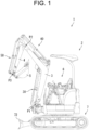
- FIG. 1 is a side diagram of the construction machine 1 according to the present embodiment.
- the construction machine 1 according to the present embodiment is a backhoe.
- the construction machine 1 according to the present embodiment has a machine body 2, a boom 3, an arm 4, a bucket 5, and a traveling device 7.
- the construction machine 1 according to the present embodiment is further provided with a boom actuator 30, an arm actuator 40, and an attachment actuator 50.
- the machine body 2 has a driving seat 6. An operator sits in the driving seat 6 and operates the construction machine 1.
- the machine body 2 is supported by the traveling device 7.
- the machine body 2 may be swivelably supported by the traveling device 7.
- the machine body 2 is provided with an engine, a fuel tank, a battery, a hydraulic system, and a hydraulic oil tank.
- a hood that houses the engine, the fuel tank, the battery, the hydraulic system, and the hydraulic oil tank, and the driving seat 6 is arranged on the hood.
- the boom 3 is supported on the machine body 2 so as to freely oscillate around a first rotation fulcrum P1. Specifically, a base end part of the boom 3 is pivotally supported on by the machine body 2.
- the first rotation fulcrum P1 is a rotary axis that extends along a left and right direction in viewing the driving seat 6 from the front.
- the left and right direction in viewing the driving seat 6 from the front may be described as "the left and right direction”.
- the boom actuator 30 operates the boom 3. Specifically, as a result of the expansion and contraction of the boom actuator 30, the boom 3 oscillates around the first rotation fulcrum P1.
- the supply of hydraulic oil to the boom actuator 30 and the discharge of hydraulic oil from the boom actuator 30 are controlled to expand and contract the boom actuator 30.
- the boom actuator 30 is expanded and contracted by hydraulic oil.
- the arm 4 is supported on the boom 3 so as to freely oscillate around a second rotation fulcrum P2. Specifically, a base end part of the arm 4 is pivotally supported at a distal end part of the boom 3.
- the second rotation fulcrum P2 is a rotary axis that extends along the left and right direction.
- the arm actuator 40 operates the arm 4. Specifically, as a result of the expansion and contraction of the arm actuator 40, the arm 4 oscillates around the second rotation fulcrum P2.
- the supply of hydraulic oil to the arm actuator 40 and the discharge of hydraulic oil from the arm actuator 40 are controlled to expand and contract the arm actuator 40.
- the arm actuator 40 is expanded and contracted by hydraulic oil.
- the bucket 5 is a type of an attachment.
- the bucket 5 is supported on the arm 4 so as to freely oscillate around a third rotation fulcrum P3.
- the bucket 5 is pivotally supported at a distal end part of the arm 4.
- the third rotation fulcrum P3 is a rotary axis that extends along the left and right direction.
- the attachment actuator 50 operates the bucket 5. Specifically, as a result of the expansion and contraction of the attachment actuator 50, the bucket 5 oscillates around the third rotation fulcrum P3 In detail, the supply of hydraulic oil to the attachment actuator 50 and the discharge of hydraulic oil from the attachment actuator 50 are controlled to expand and contract the attachment actuator 50. Thus, the attachment actuator 50 is expanded and contracted by hydraulic oil.
- the traveling device 7 causes the construction machine 1 to travel.
- the traveling device 7 is a crawler type traveling device.
- the traveling device 7 has a blade 72.
- the blade 72 is provided on the machine body 2.
- the blade 72 is provided so as to extend in a body width direction (left and right-direction).
- the blade 72 is disposed in front of the traveling device 7.
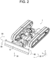
- FIG. 2 is a schematic perspective diagram of the traveling device 7 in the construction machine 1.
- the blade 72 is configured so as to be capable of performing a plurality of operations, that is to say, a lifting operation, a tilting operation, and an angular operation.
- the lifting operation indicates that the entire blade 72 moves along a direction D1 in a vertical direction.
- the tilting operation indicates that each of a left end and a right end of the blade 72 moves along a direction D2 in a vertical direction.
- the angular operation indicates that each of the left end and the right end of the blade 72 moves along a direction D3 in a forward and backward direction.
- FIG. 3 is a perspective diagram of the machine body 2 in the construction machine 1.
- the construction machine 1 is further provided with a steering unit 8 and a display device 9.
- the steering unit 8 and the display device 9 are provided on the machine body 2. Specifically, the steering unit 8 and the display device 9 are arranged in front of the driving seat 6.
- the steering unit 8 includes various kinds of manipulation members for an operator to steer the construction machine 1.
- the various kinds of manipulation members include a first manipulation lever 81, a second manipulation lever 82, and a third manipulation lever 83.
- the operator manipulates the first manipulation lever 81, the second manipulation lever 82, and the third manipulation lever 83 by hand.
- the operator can the boom 3 and the bucket 5 to operate by manipulating the first manipulation lever 81.
- the operator can cause the arm 4 to operate and cause the machine body 2 to swivel by manipulating the second manipulation lever 82.
- the operator can cause the blade 72 to operate by manipulating the third manipulation lever 83.
- the third manipulation lever 83 is one example of the "manipulation lever" according to the present invention.
- the display device 9 displays various kinds of screens.
- FIG. 4(a) is a front diagram of the third manipulation lever 83.
- FIG. 4(b) is a rear diagram of the third manipulation lever 83.
- FIG. 5 is a side diagram of the third manipulation lever 83.
- the third manipulation lever 83 has a lever body 831, a grip section 832, and a manipulation switch 833.
- the third manipulation lever 83 manipulates the blade 72.
- the third manipulation lever 83 is configured to be capable of controlling by individual different manipulations a plurality of operations of the blade 72, for example, an angular operation and a tilting operation.
- the third manipulation lever 83 is configured so as to be capable of manipulating each of the angular operation (one of the plurality of operations) and the tilting operation (another operation) in a same direction.
- the different manipulations refer, for example, to a manipulation of a different portion in the third manipulation lever 83, one of which is a manipulation of the lever body 831 and another one of which is a manipulation of the manipulation switch 833.
- the manipulations are individually different.
- the lever body 831 can be manipulated in at least one direction (for example, forward, backward, left, and right).
- the manipulations of the lever body 831 includes, for example, a manipulation for tilting the lever body 831 and a manipulation for turning the lever body 831 in a predetermined direction.
- a direction in which a rear face of the lever body 831 turns to the right side is as a right turning direction and that a direction in which it turns to the left side is as a left turning direction.
- the manipulation for tilting the lever body 831 is hereinafter described as the manipulation of the lever body 831.
- the grip section 832 is disposed at a distal end part of the lever body 831.
- the manipulation switch 833 is disposed at the grip section 832. Specifically, the manipulation switch 833 is disposed at a front side of the grip section 832. For example, the front side is a side where the driving seat 6 is located.
- the manipulation switch 833 is formed to be operable in a predetermined direction (for example, left and right, up and down) with respect to the grip section 832.
- the manipulation switch 833 is a roller switch or a slide switch.
- a tilting operation is carried out when the manipulation switch 833 is manipulated to the left or right (an arrow direction illustrated in the drawing). In detail, the tilting operation is carried out through slide-manipulation of the manipulation switch 833 to the left or right by operator's fingertip.
- the third manipulation lever 83 further has a changeover switch 834.
- the changeover switch 834 is disposed at a rear side of the grip section 832.
- the rear side is a side far from the driving seat 6.
- the changeover switch 834 is configured so as to be capable of being pushed down.
- the changeover switch 834 is disposed at the rear side of the grip section 832, so that the changeover switch 834 can be located in a position that the operator's index finger touches when the operator holds the grip section 832. Therefore, it is easier to push down the changeover switch 834.
- the changeover switch 834 enables either one of one operation (angular operation) and another operation (tilting operation) among a plurality of operations.
- the tilting operation is disabled as well as the angular operation is enabled through manipulation of the changeover switch 834.
- the tilting manipulation is disabled as well as the angle manipulation is enabled.
- the angular operation is performed by tilting the grip section 832 of the third manipulation lever 83 simultaneously with the manipulation of the changeover switch 834. That is to say, an operator tilts the grip section 832 of the third manipulation lever 83 while pressing down the changeover switch 834, so that the angular operation is performed
- a lifting operation is carried out by tilting the grip section 832 of the third manipulation lever 83 to back and forth.
- the grip section 832 is formed to incline downward from a base end part 835 thereof toward a distal end part 836 thereof.
- an operator can easily tilt the third manipulation lever 83 to back and forth.
- Either one of a tilting operation and an angular operation is performed by tilting the grip section 832 in a predetermined direction.
- the other one of the tilting operation and the angular operation is performed through manipulation of the manipulation switch 833.
- one is an angular operation.
- the angling operation is performed by tilting the grip section 832 in a predetermined direction.
- the other one is a tilting operation. In other words, the tilting operation is performed through manipulation of the manipulation switch 833.
- the third manipulation lever 83 (manipulation lever) is configured to be capable of controlling the tilting operation and the angular operation by different manipulations.
- the tilting operation is performed by finger's manipulation and the angular operation is performed by arm's manipulation.
- the possibility of malfunction can be suppressed.
- FIG. 6 is a circuit diagram illustrating a configuration of a hydraulic circuit for an angular operation and a tilting operation of the blade 72
- FIG. 7 is a circuit diagram illustrating a configuration of a hydraulic circuit for a lifting operation of the blade 72. It is noted that the circuit for the lifting operation and the circuit for the angular operation and the tilting operation may be configured as a single unit although both circuits are provided as separate units for convenience of description in the present embodiment.
- the hydraulic circuit for the angular operation and the tilting operation includes, from an upstream side of the circuit, an angle pilot valve 182 and a tilt pilot valve 184, a tilt angle control valve 140, a first switching valve 130, a tilt cylinder 110, and an angle cylinder 120.
- the angle pilot valve 182 regulates an inflow of pilot oil for an angular operation to the tilt angle control valve 140.
- hydraulic oil pilot oil
- the angle pilot valve 182 is configured so as to be able of establishing communication on the basis of manipulation signals from the third manipulation lever 83.
- the angle pilot valve 182 establishes communication when the third manipulation lever 83 is tilted in a left or right direction.
- pilot oil discharged by a pilot pump PB is output at the angle pilot valve 182 in a direction and at a flow rate corresponding to the manipulation amount determined by the third manipulation lever 83.
- the tilt pilot valve 184 regulates an inflow of pilot oil for a tilting operation to the tilt angle control valve 140.
- hydraulic oil pilot oil
- the tilt pilot valve 184 is configured so as to establish communication on the basis of manipulation signals from the manipulation switch 833.
- the tilt pilot valve 184 establishes communication when the manipulation switch 833 is manipulated in a left or right direction.
- pilot oil discharged by the pilot pump PC is output at the tilt pilot valve 184 in a direction and at a flow rate corresponding to the manipulation amount determined by the manipulation switch 833.
- Shuttle valves 162 and 164 are respectively located between the angle pilot valve 182 and the tilt angle control valve 140, and between the tilt pilot valve 184 and the tilt angle control valve 140.
- the shuttle valves 162 and 164 selectively connect either pilot oil for a tilting operation or pilot oil for an angular operation to the tilt angle control valve 140.
- the pilot oil for an angular operation is not supplied to the shuttle valve 162 when the changeover switch 834 is not pressed down, and therefore, the pilot oil for a tilting operation is preferentially supplied to the tilt angle control valve 140.
- the changeover switch 834 is pressed down, the pilot oil for an angular operation is preferentially supplied to the tilt angle control valve 140.
- a second switching valve 170 is disposed between the tilt angle control valve 140 and the angle pilot valve 182.
- the second switching valve 170 regulates communication between oil paths on the basis of switching signals from the changeover switch 834.
- the changeover switch 834 is pressed down, the pilot oil for an angular operation output from the angle pilot valve 182 is supplied to the shuttle valve 162.
- the changeover switch 834 is not pressed down, the pilot oil for an angular operation output from the angle pilot valve 182 is discharged to a tank T.
- the tilt angle control valve 140 controls the supply and discharge of hydraulic oil to either one of the tilt cylinder 110 or the angle cylinder 120, and controls an expanding and contracting operation of either one of the tilt cylinder 110 or the angle cylinder 120.
- hydraulic oil discharged by a main pump PA is supplied to the tilt cylinder 110 or the angle cylinder 120 in a direction and at a flow rate corresponding to a tilt pilot signal (pilot oil) or an angle pilot signal (pilot oil).
- the first switching valve 130 selects either one of the tilt cylinder 110 or the angle cylinder 120 and connects it to the tilt angle control valve 140.
- the first switching valve 130 selects either one of the tilt cylinder 110 or the angle cylinder 120 and connects the selected one to the tilt angle control valve 140, depending on whether the changeover switch 834 is pressed down.
- the first switching valve 130 in a case where the changeover switch 834 is not pressed down, connects the tilt cylinder 110 to the tilt angle control valve 140.
- the first switching valve 130 connects the angle cylinder 120 to the tilt angle control valve 140.
- the tilt cylinder 110 performs an expanding and contracting operation to cause the blade 72 to perform a tilting operation.
- the angle cylinder 120 performs an expanding and contracting operation to cause the blade 72 to perform an angular operation.
- the hydraulic circuit for the angular operation and tilting operation of the blade 72 has a relief valve 150 disposed therein between the first switching valve 130 and the tilt angle control valve 140.
- the relief valve 150 prevents an excessive discharge pressure of a bottom chamber or a rod chamber of the tilt cylinder 110 or of a bottom chamber or a rod chamber of the angle cylinder 120 from being caused.
- the relief valve 150 can release an internal pressure in the circuit by allowing oil to flow to the tank T.
- the first switching valve 130 and the second switching valve 170 can be switched on the basis of switching signals from the changeover switch 834, thereby preventing malfunctions of the tilting operation and the angular operation.
- the hydraulic circuit for a lifting operation includes, from an upstream side of the circuit, a lift pilot valve 282, a lift control valve 240, and a lift cylinder 210.
- the lift pilot valve 282 regulates an inflow of pilot oil for a lifting operation to the lift control valve 240.
- the hydraulic oil (pilot oil) can be sent to the lift control valve 240 at a pressure (pilot pressure) corresponding to a manipulation amount determined by the grip section 832 in the third manipulation lever 83.
- the lift pilot valve 282 is configured so as to establish communication on the basis of manipulation signals from the third manipulation lever 83.
- the lift pilot valve 282 is communicated when the third manipulation lever 83 is tilted in a forward and backward direction.
- pilot oil that has been discharged by the pilot pump PE is output at the lift pilot valve 282 in a direction and at a flow rate corresponding to the manipulation amount determined by the third manipulation lever 83.
- the lift control valve 240 controls an expanding and contracting operation of the lift cylinder 210.
- the hydraulic oil discharged by a main pump PD is supplied to the lift cylinder 210 in a direction and at a flow rate corresponding to a lift pilot signal (pilot oil).
- the lift cylinder 210 performs an expanding and contracting operation to cause the blade 72 to perform a lifting operation.
- the hydraulic circuit for the lifting operation of the blade 72 has a relief valve 250 disposed therein between the lift cylinder 210 and the lift control valve 240.
- the relief valve 250 prevents an excessive discharge pressure of a bottom chamber or a rod chamber of the lift cylinder 210 from being caused.
Landscapes
- Engineering & Computer Science (AREA)
- Mining & Mineral Resources (AREA)
- Civil Engineering (AREA)
- General Engineering & Computer Science (AREA)
- Structural Engineering (AREA)
- Mechanical Engineering (AREA)
- Physics & Mathematics (AREA)
- General Physics & Mathematics (AREA)
- Automation & Control Theory (AREA)
- Operation Control Of Excavators (AREA)
- Mechanical Control Devices (AREA)
Applications Claiming Priority (2)
| Application Number | Priority Date | Filing Date | Title |
|---|---|---|---|
| JP2020210240A JP7365323B2 (ja) | 2020-12-18 | 2020-12-18 | 建設機械 |
| PCT/JP2021/046841 WO2022131376A1 (ja) | 2020-12-18 | 2021-12-17 | 建設機械 |
Publications (2)
| Publication Number | Publication Date |
|---|---|
| EP4265850A1 true EP4265850A1 (de) | 2023-10-25 |
| EP4265850A4 EP4265850A4 (de) | 2024-11-13 |
Family
ID=82057631
Family Applications (1)
| Application Number | Title | Priority Date | Filing Date |
|---|---|---|---|
| EP21906734.5A Pending EP4265850A4 (de) | 2020-12-18 | 2021-12-17 | Baumaschine |
Country Status (6)
| Country | Link |
|---|---|
| US (1) | US12624525B2 (de) |
| EP (1) | EP4265850A4 (de) |
| JP (1) | JP7365323B2 (de) |
| KR (1) | KR20230118823A (de) |
| CN (1) | CN116685744A (de) |
| WO (1) | WO2022131376A1 (de) |
Cited By (1)
| Publication number | Priority date | Publication date | Assignee | Title |
|---|---|---|---|---|
| EP4575101A1 (de) * | 2023-12-06 | 2025-06-25 | Yanmar Holdings Co., Ltd. | Betriebssystem und arbeitsmaschine |
Families Citing this family (2)
| Publication number | Priority date | Publication date | Assignee | Title |
|---|---|---|---|---|
| JP7843694B2 (ja) * | 2022-12-27 | 2026-04-10 | 株式会社クボタ | 作業車両の操作装置、及び作業車両 |
| US20240208327A1 (en) * | 2022-12-27 | 2024-06-27 | Kubota Corporation | Operating device for working vehicle |
Family Cites Families (10)
| Publication number | Priority date | Publication date | Assignee | Title |
|---|---|---|---|---|
| US3517568A (en) * | 1968-07-05 | 1970-06-30 | North American Rockwell | Single lever control |
| US5620053A (en) * | 1994-01-28 | 1997-04-15 | Komatsu, Ltd. | Blade apparatus and its control method in bulldozer |
| JPH08270017A (ja) * | 1995-03-31 | 1996-10-15 | Mitsubishi Heavy Ind Ltd | 作業機の操作レバー及びブルドーザ |
| JPH11191014A (ja) * | 1997-12-26 | 1999-07-13 | Mitsubishi Agricult Mach Co Ltd | 操作レバーのグリップ構造 |
| JP3531903B2 (ja) * | 1998-03-30 | 2004-05-31 | 新キャタピラー三菱株式会社 | 小型油圧ショベル |
| US7059124B2 (en) * | 2003-12-01 | 2006-06-13 | Komatsu Ltd. | Hydraulic control apparatus for work machines |
| JP2005207196A (ja) * | 2004-01-26 | 2005-08-04 | Shin Caterpillar Mitsubishi Ltd | 作業機械 |
| JP6129008B2 (ja) * | 2013-07-22 | 2017-05-17 | 株式会社クボタ | ドーザレバー |
| JP6532797B2 (ja) * | 2015-10-08 | 2019-06-19 | 日立建機株式会社 | 建設機械 |
| JP6872508B2 (ja) * | 2018-03-22 | 2021-05-19 | 株式会社日立建機ティエラ | 建設機械 |
-
2020
- 2020-12-18 JP JP2020210240A patent/JP7365323B2/ja active Active
-
2021
- 2021-12-17 CN CN202180083932.5A patent/CN116685744A/zh active Pending
- 2021-12-17 EP EP21906734.5A patent/EP4265850A4/de active Pending
- 2021-12-17 WO PCT/JP2021/046841 patent/WO2022131376A1/ja not_active Ceased
- 2021-12-17 KR KR1020237018529A patent/KR20230118823A/ko active Pending
- 2021-12-17 US US18/037,052 patent/US12624525B2/en active Active
Cited By (1)
| Publication number | Priority date | Publication date | Assignee | Title |
|---|---|---|---|---|
| EP4575101A1 (de) * | 2023-12-06 | 2025-06-25 | Yanmar Holdings Co., Ltd. | Betriebssystem und arbeitsmaschine |
Also Published As
| Publication number | Publication date |
|---|---|
| JP2022096946A (ja) | 2022-06-30 |
| KR20230118823A (ko) | 2023-08-14 |
| WO2022131376A1 (ja) | 2022-06-23 |
| JP7365323B2 (ja) | 2023-10-19 |
| CN116685744A (zh) | 2023-09-01 |
| US12624525B2 (en) | 2026-05-12 |
| EP4265850A4 (de) | 2024-11-13 |
| US20240026642A1 (en) | 2024-01-25 |
Similar Documents
| Publication | Publication Date | Title |
|---|---|---|
| US12624525B2 (en) | Construction machine | |
| EP2987672B1 (de) | Bediensystem | |
| US11053665B2 (en) | System and method for control of a work vehicle | |
| US8700271B2 (en) | Machine with four degrees of freedom implement control joystick and track type tractor using same | |
| US8650778B2 (en) | Hydraulic drive device for hydraulic working machine | |
| JP6156871B2 (ja) | 作業車両 | |
| CN111287230B (zh) | 用于作业机械的附接件可配置系统 | |
| JP2013227002A (ja) | ホイールローダのステアリング装置 | |
| US20230084302A1 (en) | Construction Machine | |
| EP3569771B1 (de) | Arbeitsmaschinen-steuerknüppelanordnung | |
| CN107960111A (zh) | 施工机器的行进控制系统 | |
| JP2021121765A (ja) | 作業機の油圧システム | |
| JP7793058B2 (ja) | 油圧制御装置 | |
| US9624646B2 (en) | Working machine and method for operating working machine | |
| JP6896558B2 (ja) | 作業機械 | |
| WO2022131195A1 (ja) | 弁ユニットおよび弁装置 | |
| US20250188706A1 (en) | Operation system and work machine | |
| JP4521866B2 (ja) | 建設機械の油圧制御装置 | |
| JP2000008400A (ja) | 油圧ショベル | |
| KR101877059B1 (ko) | 건설기계의 제어장치 | |
| JP2012197835A (ja) | 作業機械 | |
| JPH10331202A (ja) | 作業機の操作スタンド装置 | |
| JPH1037234A (ja) | 建設機械の油圧回路 |
Legal Events
| Date | Code | Title | Description |
|---|---|---|---|
| STAA | Information on the status of an ep patent application or granted ep patent |
Free format text: STATUS: THE INTERNATIONAL PUBLICATION HAS BEEN MADE |
|
| PUAI | Public reference made under article 153(3) epc to a published international application that has entered the european phase |
Free format text: ORIGINAL CODE: 0009012 |
|
| STAA | Information on the status of an ep patent application or granted ep patent |
Free format text: STATUS: REQUEST FOR EXAMINATION WAS MADE |
|
| 17P | Request for examination filed |
Effective date: 20230601 |
|
| AK | Designated contracting states |
Kind code of ref document: A1 Designated state(s): AL AT BE BG CH CY CZ DE DK EE ES FI FR GB GR HR HU IE IS IT LI LT LU LV MC MK MT NL NO PL PT RO RS SE SI SK SM TR |
|
| DAV | Request for validation of the european patent (deleted) | ||
| DAX | Request for extension of the european patent (deleted) | ||
| A4 | Supplementary search report drawn up and despatched |
Effective date: 20241014 |
|
| RIC1 | Information provided on ipc code assigned before grant |
Ipc: E02F 3/96 20060101ALI20241008BHEP Ipc: E02F 3/32 20060101ALI20241008BHEP Ipc: G05G 1/06 20060101ALI20241008BHEP Ipc: G05G 1/02 20060101ALI20241008BHEP Ipc: G05G 9/047 20060101ALI20241008BHEP Ipc: E02F 9/20 20060101ALI20241008BHEP Ipc: E02F 3/815 20060101AFI20241008BHEP |