EP4265863A1 - Befestigungselement und spannbeton - Google Patents
Befestigungselement und spannbeton Download PDFInfo
- Publication number
- EP4265863A1 EP4265863A1 EP21906536.4A EP21906536A EP4265863A1 EP 4265863 A1 EP4265863 A1 EP 4265863A1 EP 21906536 A EP21906536 A EP 21906536A EP 4265863 A1 EP4265863 A1 EP 4265863A1
- Authority
- EP
- European Patent Office
- Prior art keywords
- barrel member
- anchoring device
- fiber reinforced
- reinforced resin
- peripheral surface
- Prior art date
- Legal status (The legal status is an assumption and is not a legal conclusion. Google has not performed a legal analysis and makes no representation as to the accuracy of the status listed.)
- Pending
Links
Images




Classifications
-
- E—FIXED CONSTRUCTIONS
- E04—BUILDING
- E04C—STRUCTURAL ELEMENTS; BUILDING MATERIALS
- E04C5/00—Reinforcing elements, e.g. for concrete; Auxiliary elements therefor
- E04C5/08—Members specially adapted to be used in prestressed constructions
- E04C5/12—Anchoring devices
- E04C5/122—Anchoring devices the tensile members are anchored by wedge-action
-
- E—FIXED CONSTRUCTIONS
- E04—BUILDING
- E04C—STRUCTURAL ELEMENTS; BUILDING MATERIALS
- E04C5/00—Reinforcing elements, e.g. for concrete; Auxiliary elements therefor
- E04C5/08—Members specially adapted to be used in prestressed constructions
- E04C5/12—Anchoring devices
- E04C5/127—The tensile members being made of fiber reinforced plastics
Definitions
- the present invention relates to an anchoring device and a prestressed concrete (PC), and more specifically relates to an anchoring device used to tension a wire in a prestressed concrete and the prestressed concrete.
- PC prestressed concrete
- a wedge-type anchoring device including a barrel member (sleeve member) which is fixed to a PC concrete block and has a through hole having a tapered shape, and multiple wedge members which each have an outer peripheral surface having a tapered shape and slidably contacting an inner peripheral surface of the through hole and which cooperate with each other to grip the wire (for example, Patent Document 1).
- the barrel member is fixed to the concrete block, and the end of the wire is gripped or anchored by the multiple wedge members according to wedge action of the wedge members being pushed into the tapered side of the through hole.
- Patent Document 1 JPH11-210163 A
- General wedge-type anchoring devices which are conventionally known may have a barrel member made of steel or a barrel member made of resin. Those with a barrel member made of steel have sufficient strength against diameter expansion deformation of the barrel member due to wedge action, but corrosion (rust) may occur depending on environmental conditions. Those with a barrel member made of resin do not cause corrosion but are difficult to have sufficient strength against the diameter expansion deformation of the barrel member due to wedge action.
- a task to be accomplished by the present invention is to provide a wedge-type anchoring device in which the barrel member does not corrode, and which has sufficient strength against the diameter expansion deformation of the barrel member due to wedge action.
- An anchoring device is an anchoring device (10) for an end of a wire (110), comprising: a barrel member (12) which is composed of resin or mortar and has a through hole (14) having a tapered shape; multiple wedge members (20) which each have an outer peripheral surface (20A) having a tapered shape and slidably contacting an inner peripheral surface (14A) of the through hole and which cooperate with each other to grip the wire; and a reinforcement member (16, 52, 60, 70) including a part that extends in a circumferential direction of the barrel member to suppress diameter expansion deformation of the barrel member.
- the barrel member does not corrode, and sufficient strength against the diameter expansion deformation of the barrel member due to wedge action is provided.
- each wedge member is composed of resin or fiber reinforced resin.
- the wedge members do not corrode.
- the reinforcement member comprises fibers (16, 52) embedded in the barrel member.
- the barrel member and the reinforcement member can be integrally molded, which allows excellent productivity of the anchoring device.
- the barrel member is composed of a prepreg (42, 44, 46, 48) wound cylindrically so as to have an outer peripheral surface (42A, 44A, 46A, 48A) tapered in steps in a direction same as that of the tapered shape of the through hole, the prepreg comprises a base material (50) made of resin and fibers (52) impregnated in the base material, and the reinforcement member is composed of fibers comprised in the prepreg.
- the barrel member including the reinforcement member is manufactured efficiently by using the prepreg, whereby the productivity is excellent. Further, the wall thickness of the barrel member can be made close to a uniform thickness over the entire length in the axial direction, and the barrel member can be made compact and lightweight.
- the prepreg is composed of multiple strip-shaped bodies disposed to overlap with each other in a radial direction at parts in an axial direction of the through hole.
- the required shape of the barrel member is reliably formed by the prepreg.
- the reinforcement member comprises an annular body (30) provided on an outer circumference of the barrel member to surround the barrel member.
- the diameter expansion of the barrel member is effectively suppressed by the annular body, whereby the diameter expansion deformation of the barrel member due to wedge action is effectively suppressed.
- the barrel member is composed of fiber reinforced resin
- the annular body is composed of fiber reinforced resin having a higher Young's modulus than the fiber reinforced resin composing the barrel member.
- the annular body is provided partially in an axial direction of the through hole.
- the material cost is reduced compared to a case where the annular body is provided over the entirety in the axial direction of the through hole.
- the annular body is provided continuously over an entirety in an axial direction of the through hole.
- the barrel member has an outer peripheral surface (12C) having a cylindrical shape
- the reinforcement member comprises a spiral restraint body (60) wound on the outer peripheral surface of the barrel member.
- the diameter expansion of the barrel member is effectively suppressed by the spiral restraint body, whereby the diameter expansion deformation of the barrel member due to wedge action is effectively suppressed.
- the barrel member is composed of fiber reinforced resin
- the spiral restraint body is composed of fiber reinforced resin having a higher Young's modulus than the fiber reinforced resin composing the barrel member.
- the diameter expansion deformation of the barrel member is reliably suppressed, and in addition, the material cost is reduced compared to a case where the barrel member also is composed of fiber reinforced resin having a high Young's modulus.
- the barrel member has a spiral groove (12D) on the outer peripheral surface, and the spiral restraint body is fitted in the spiral groove.
- the barrel member has an outer peripheral surface (12E) having a conical shape
- the reinforcement member comprises an annular restraint body (70) fitted on the outer peripheral surface of the barrel member.
- the annular restraint body acts to suppress the diameter expansion of the barrel member, whereby the diameter expansion deformation of the barrel member due to wedge action is suppressed.
- the barrel member is composed of fiber reinforced resin
- the annular restraint body is composed of fiber reinforced resin having a higher Young's modulus than the fiber reinforced resin composing the barrel member.
- the diameter expansion deformation of the barrel member is reliably suppressed, and in addition, the material cost is reduced compared to a case where the barrel member also is composed of fiber reinforced resin having a high Young's modulus.
- an end surface (70B) of the annular restraint body on a tapered side of the conical shape of the barrel member includes a surface perpendicular to an axial direction of the barrel member.
- a prestressed concrete according to one embodiment of the present invention comprises: a concrete block having a rectangular parallelepiped shape; a wire penetrating in a longitudinal direction of the concrete block; and the anchoring device according to the above-described embodiment which is provided at each of two end portions of the concrete block in the longitudinal direction and to which an end portion of the wire is locked.
- the anchoring device may either be embedded in the concrete block or be mounted to the concrete block such that one end surface (12B) of the barrel member contacts an end surface of the concrete block and an outer peripheral surface (12C, 12E) of the barrel member is exposed to outside.
- a prestressed concrete 100 includes a concrete block 102 molded in a rectangular parallelepiped shape, a cylindrical sheath 104 made of resin and embedded in the concrete block 102 to extend in the longitudinal direction of the concrete block 102, and a cable (wire) 106 composed of fiber reinforced resin or metal and disposed in the sheath 104 to penetrate the concrete block 102 in the longitudinal direction.
- a space between the sheath 104 and the cable 106 is filled with grout 108 consisting of cement mortar or the like.
- the prestressed concrete 100 further includes left and right anchoring devices 10 which are provided at both longitudinal end portions of the concrete block 102 (left and right end portions as seen in Figure 1 ) and to which the end portions of the cable 106 are locked.
- the left and right anchoring devices 10 sandwich the concrete block 102 from both sides in the longitudinal direction and fix (anchor) the cable 106 in the concrete block 102 to be in a state of tension. Thereby, prestress is given to the concrete block 102.
- the left and right anchoring devices 10 are of a wedge type and each include a cylindrical barrel member 12 and a pair of upper and lower wedge members 20 as seen in Figure 1 . Since the left and right anchoring devices 10 have the same structure, in the following, description will be made taking the anchoring device 10 disposed on the left side as an example.
- the barrel member 12 includes an outer end 12A exposed to outside from the concrete block 102, an inner end 12B joined to an end surface 110A of an anchoring device embedding hole 110 of the concrete block 102, and an outer peripheral surface 12C joined to an inner peripheral surface 110B of the anchoring device embedding hole 110, and the entirety of the barrel member 12 is embedded in an end portion of the concrete block 102.
- the barrel member 12 is fixed to the concrete block 102 so as not to be displaceable both in the axial direction (the left-right direction as seen in Figure 2 ), which is a direction of prestress application to the concrete block 102 and in the radial direction.
- the embedding of the barrel member 12 in the concrete block 102 may be performed when the concrete block 102 is molded.
- the anchoring device embedding hole 110 is formed when the concrete block 102 is molded.
- the barrel member 12 has a through hole 14 extending through a central part thereof in the axial direction.
- the through hole 14 is a hole having a tapered shape extending from the outer end 12A to the inner end 12B of the barrel member 12, with both ends open.
- the through hole 14 is a tapered hole having an inner diameter gradually decreasing from the outer end 12A to the inner end 12B of the barrel member 12.
- the barrel member 12 is a molded product made of resin such as epoxy resin, polyester resin, or the like. As shown in Figure 2(A) , the barrel member 12 has mesh-like or sheet-like fibers 16 embedded therein.
- the fibers 16 may be glass fibers, carbon fibers, boron fibers, aramid fibers, basalt fibers, or the like, and are present in the barrel member 12 in a form wound cylindrically around the central axis of the through hole 14 to form multiple layers. Thereby, the fibers 16 constitute a reinforcement member including a part that continuously extends in the circumferential direction of the barrel member 12.
- the fibers 16 may be a bundle of fibers wound multiple times around the central axis of the through hole 14 in form of helices with different diameters.
- the fibers 16 constitute a reinforcement member continuously extending in the circumferential direction of the barrel member 12.
- the fibers 16 increases an apparent tensile strength and Young's modulus (longitudinal elastic modulus) of the barrel member 12 in the diameter expansion direction and thereby suppresses the diameter expansion deformation of the barrel member 12.
- the fibers 16 include a part continuously extending around the central axis of the through hole 14, but may be discontinuous depending on the required tensile strength and Young's modulus of the barrel member 12 in the radial direction.
- Each wedge member 20 is a molded product made of resin or fiber reinforced resin, has a shape formed by dividing a tapered rod in half, and has an outer peripheral surface 20A having a tapered shape and slidably contacting the inner peripheral surface 14A of the through hole 14 and a cable groove 20B having a substantially semicircular cross-sectional shape and opened in a halved surface 20C.
- the two wedge members 20 cooperate with each other to grip an end of the cable 106 engaged with the cable groove 20B and in the state of tension, and are pressed toward the tapered side of the through hole 14, in other words, are driven into the tapered side of the through hole 14, to increase the friction resistance against the cable 106 due to wedge action with respect to the barrel member 12 and to lock (anchor) the end of the cable 106 to the concrete block 102 via the barrel member 12.
- the barrel member 12 is composed of resin instead of steel to prevent rust, the barrel member 12 is provided with sufficient strength against the diameter expansion deformation due to wedge action, and thus, reduction of wedge action is prevented.
- the barrel member 12 does not corrode even when used over an extended period of time, and sufficient strength against the diameter expansion deformation of the barrel member 12 due to wedge action is provided, whereby lowering of the anchoring strength of the cable 106 due to the diameter expansion deformation of the barrel member 12 is prevented.
- the wedge member 20 also is a molded product made of resin or fiber reinforced resin, the wedge member 20 does not corrode in use over an extended period of time.
- the fibers 16 and the barrel member 12 are integrally molded, which allows excellent productivity of the anchoring device 10.
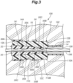
- multiple annular bodies 30 are provided on the outer circumference of the cylindrical barrel member 12 at a predetermined interval in the extension direction (axial direction) of the through hole 14. As seen in the axial direction of the through hole 14, the multiple annular bodies 30 are partially provided on the barrel member 12.
- Each annular body 30 has an annular shape continuously extends around the outer circumference of the barrel member 12, namely, is provided to completely surround the outer circumference of the barrel member 12.
- Each annular body 30 is integrally molded with the barrel member 12 or retrofitted on the barrel member 12.
- the annular body 30 is composed of fiber reinforced resin.
- the fibers (not shown in the drawings) contained in the fiber reinforced resin may be glass fibers, carbon fibers, boron fibers, aramid fibers, basalt fibers, or the like. These fibers may be mesh-like or sheet-like fibers wound cylindrically around the central axis of the through hole 14 to form multiple layers, and include a part continuously extending in the circumferential direction of the barrel member 12.
- each annular body 30 may be a bundle of fibers wound multiple times around the central axis of the through hole 14 in form of helices with different diameters.
- the fibers contained in the annular body 30 include a part continuously extending in the circumferential direction of the barrel member 12.
- each annular body 30 acts as a reinforcement member that suppresses the diameter expansion deformation of the barrel member 12, and this makes the barrel member 12 difficult to undergo diameter expansion deformation even further.
- Each annular body 30 may be composed of fiber reinforced resin containing high-tensile fibers having a Young's modulus and a tensile strength higher than those of the fibers 16 embedded in the barrel member 12, such as carbon fiber reinforced resin and the like.
- each annular body 30 is composed of fiber reinforced resin having a higher Young's modulus than the fiber reinforced resin composing the barrel member 12. With the high-tensile fibers contained in the fiber reinforced resin, each annular body 30 exerts a reinforcing effect to suppress diameter expansion deformation of the barrel member 12.
- the barrel member 12 does not corrode.
- the barrel member 12 is provided with sufficient strength against the diameter expansion deformation due to wedge action, whereby lowering of the anchoring strength of the cable 106 due to the diameter expansion deformation of the barrel member 12 is prevented.
- the fibers 16 embedded in the barrel member 12 and the fibers in the fiber reinforced resin composing the annular bodies 30 are composed of different materials and the fibers 16 are composed of glass fibers cheaper than carbon fibers or the like contained in the annular bodies 30, strength similar to when the barrel member 12 is composed of expensive carbon fiber reinforced resin or the like (strength that suppresses the diameter expansion deformation of the barrel member 12) is obtained due to the high reinforcing effect of each annular body 30. Therefore, the material cost of the barrel member 12 is saved (reduced), and in addition, the diameter expansion deformation of the barrel member 12 is effectively suppressed.
- each annular body 30 is partially provided in the axial direction of the barrel member 12, the material cost of the annular bodies 30 is reduced compared to a case where an annular body 30 is provided continuously over the entire length of the barrel member 12.
- each annular body 30 When embedded in the concrete block 102 with the barrel member 12, an annular end surface 30A of each annular body 30 is joined to the concrete block 102. This enhances the bonding strength between the barrel member 12 and the concrete block 102. In other words, the end surface 30A of each annular body 30 functions as a barrier surface that prevents the barrel member 12 from moving in the axial direction relative to the concrete block 102.
- the annular body 30 is composed of a cylindrical body having a substantially same axial length as the axial length of the barrel member 12 and provided on the outer circumference of the barrel member 12.
- the fibers contained in the annular body 30 preferably include a part continuously extending around the central axis of the through hole 14. These fibers may be mesh-like or sheet-like fibers wound in the circumferential direction, may be wound in two directions of the circumferential direction and the axial direction and pasted together, or may be woven in two directions and wound.
- the annular body 30 may be composed of fiber reinforced resin containing high-tensile fibers having a Young's modulus and a tensile strength higher than those of the fibers 16 embedded in the barrel member 12, such as carbon fiber reinforced resin and the like.
- the annular body 30 is composed of fiber reinforced resin having a higher Young's modulus than the fiber reinforced resin composing the barrel member 12.
- the fibers 16 embedded in the barrel member 12 and the fibers in the fiber reinforced resin composing the annular bodies 30 are composed of different materials and the fibers 16 are composed of glass fibers cheaper than carbon fibers or the like contained in the annular bodies 30, strength similar to when the barrel member 12 is composed of expensive carbon fiber reinforced resin or the like (strength that suppresses the diameter expansion deformation of the barrel member 12) is obtained due to the high reinforcing effect of each annular body 30. Therefore, the material cost of the barrel member 12 is reduced, and in addition, the diameter expansion deformation of the barrel member 12 is effectively suppressed.
- Embodiment 3 the effect of suppressing the diameter expansion deformation of the barrel member 12 by the annular body 30 is obtained substantially uniformly over the entirety of the axial length of the barrel member 12.
- the barrel member 12 does not corrode even when used over an extended period of time, and sufficient strength against the diameter expansion deformation of the barrel member 12 due to wedge action is provided, whereby lowering of the anchoring strength of the cable 106 due to the diameter expansion deformation of the barrel member 12 is prevented.
- the barrel member 12 is composed of multiple strip-shaped prepregs 42, 44, 46, 48 which are wound cylindrically to have outer peripheral surfaces 42A, 44A, 46A, 48A which are tapered in steps in the same direction as the tapered shape of the through hole 14.
- the outer winding diameters of the prepregs 42, 44, 46, 48 become smaller in steps from the prepreg 48 which is positioned on the side of the outer end 12A of the barrel member 12 to the prepreg 42 which is positioned on the side of the inner end 12B.
- the barrel member 12 is manufactured from an assembly 40 in which the prepregs 42, 44, 46, 48 consisting of multiple strip-shaped bodies having mutually different axial lengths, thicknesses, outer winding diameters, and inner winding diameters, namely, multiple strip-shaped bodies made of prepregs, are arranged such that adjacent ones thereof overlap with each other in the radial direction at parts in the axial direction.
- the barrel member 12 is obtained by forming the through hole 14 by cutting after curing of the prepregs 42, 44, 46, 48 in the assembly 40.
- the prepregs 42, 44, 46, 48 are formed by impregnating fibers 52 in a matrix (base material) 50 such as epoxy resin.
- the fibers 52 may be glass fibers, carbon fibers, boron fibers, aramid fibers, basalt fibers, or the like.
- the fibers 52 are mesh-like or sheet-like fibers and are present in the matrix 50 in a form wound cylindrical around the central axis of the through hole 14 to form multiple layers.
- the fibers 52 constitute a reinforcement member including a part continuously extending in the circumferential direction of the barrel member 12 composed of the matrix 50.
- the fibers 52 may be a bundle of fibers wound multiple times around the central axis of the through hole 14 in form of helices with different diameters.
- the fibers 52 constitute a reinforcement member continuously extending in the circumferential direction of the barrel member 12.
- Embodiment 4 also, similarly to Embodiment 1, a load urging the barrel member 12 to undergo diameter expansion deformation acts on the barrel member 12 due to wedge action resulting from the driving of the wedge members 20.
- the fibers 52 act as a reinforcement member to suppress the diameter expansion deformation of the barrel member 12.
- the barrel member 12 is composed of matrix resin instead of steel to prevent rust, the barrel member 12 is provided with sufficient strength against the diameter expansion deformation due to wedge action, and thus, reduction of wedge action is prevented.
- the barrel member 12 does not corrode even when used over an extended period of time, and sufficient strength against the diameter expansion deformation of the barrel member 12 due to wedge action is provided, whereby lowering of the anchoring strength of the cable 106 due to the diameter expansion deformation of the barrel member 12 is prevented.
- the barrel member 12 including the reinforcement member is manufactured efficiently by using the prepregs 42, 44, 46, 48, whereby the productivity is excellent. Since the prepregs 42, 44, 46, 48 are composed of multiple strip-shaped bodies arranged to overlap with each other in the radial direction at parts in the axial direction of the through hole 14, the barrel member 12 having a predetermined shape is reliably formed by the prepregs 42, 44, 46, 48.
- the barrel member 12 has a shape tapered in steps in the same direction as the through hole 14 due to the outer peripheral surfaces 42A, 44A, 46A, 48A of the respective prepregs 42, 44, 46, 48, a change in the wall thickness in the axial direction of the barrel member 12 is smaller than in Embodiment 1.
- the barrel member 12 is manufactured efficiently by using the prepregs 42, 44, 46, 48, whereby the productivity is excellent and, in addition, the wall thickness of the barrel member 12 can be made close to a uniform thickness over the entire length in the axial direction. Further, the wall thickness of the barrel member 12 can be made close to the minimum required thickness over the entire axial length, and the barrel member 12 can be made compact and lightweight.
- end surfaces 42B, 44B, 46B, 48B of the cured prepregs 42, 44, 46, 48 on the side of the inner end 12B function as barrier surfaces that enhance the bonding strength between the barrel member 12 and the concrete block 102 and prevent the barrel member 12 from moving in the axial direction (rightward) relative to the concrete block 102.
- the barrel member 12 is a cylindrical molded product made of fiber reinforced resin composed of matrix resin such as epoxy resin, polyester resin, or the like and fibers such as glass fibers, carbon fibers, boron fibers, aramid fibers, basalt fibers, or the like, and is molded in a cylindrical shape having a through hole 14.
- the barrel member 12 may be a product similar to the barrel member 12 of Embodiment 1.
- the outer peripheral surface 12C of the barrel member 12 is formed with a spiral groove 12D having a semi-circular cross section with a predetermined pitch substantially over the entire length of the axial direction of the barrel member 12.
- a spiral restraint body 60 having a circular cross section is fitted.
- the spiral restraint body 60 is a molded product made of fiber reinforced resin composed of matrix resin such as epoxy resin, polyester resin, or the like and fibers such as glass fibers, carbon fibers, boron fibers, aramid fibers, basalt fibers, steel fibers, or the like.
- the spiral restraint body 60 is wound on the outer peripheral surface 12C of the barrel member 12 and constitutes a reinforcement member including a part extending in the circumferential direction of the barrel member 12. Since the spiral restraint body 60 is fitted in the spiral groove 12D, the spiral restraint body 60 does not shift relative to the barrel member 12 at such time as when manufacturing the concrete block 102, and the placement position of the spiral restraint body 60 with respect to the barrel member 12 does not fluctuate. This stabilizes the effect of suppression of the diameter expansion deformation of the barrel member 12 by the spiral restraint body 60.
- the fitting of the spiral restraint body 60 to the spiral groove 12D may be achieved by moving the spiral restraint body 60 in the axial direction relative to the barrel member 12 from the side of one end of the barrel member 12, with the spiral restraint body 60 deformed to have an expanded diameter such that the inner diameter of the spiral restraint body 60 is larger than the outer diameter of the barrel member 12, and releasing the diameter expansion deformation at a position where the spiral restraint body 60 aligns with the spiral groove 12D in the axial direction, or by making the spiral groove 12D threadedly engaged with the spiral restraint body 60 from the side of one end of the barrel member 12 while rotating the spiral restraint body 60 relative to the barrel member 12.
- Embodiment 5 also, similarly to Embodiment 1, a load urging the barrel member 12 to undergo diameter expansion deformation acts on the barrel member 12 due to wedge action resulting from the driving of the wedge members 20.
- the spiral restraint body 60 acts as a reinforcement member to suppress the diameter expansion deformation of the barrel member 12.
- the spiral restraint body 60 is fitted in the spiral groove 12D in a preloaded state.
- the barrel member 12 is composed of matrix resin instead of steel to prevent rust, the barrel member 12 is provided with sufficient strength against the diameter expansion deformation due to wedge action, and thus, reduction of wedge action is prevented.
- the diameter expansion deformation of the barrel member 12 is effectively suppressed by the spiral restraint body 60. Accordingly, the barrel member 12 does not corrode even when used over an extended period of time, while the barrel member 12 is provided with sufficient strength against the diameter expansion deformation due to wedge action, whereby lowering of the anchoring strength of the cable 106 due to the diameter expansion deformation of the barrel member 12 is effectively prevented.
- the spiral restraint body 60 may be composed of high-tensile fiber reinforced resin having a Young's modulus and a tensile strength higher than those of the barrel member 12.
- the spiral restraint body 60 is composed of fiber reinforced resin having a higher Young's modulus than the fiber reinforced resin composing the barrel member 12.
- the barrel member 12 is composed of reinforced resin containing glass fibers cheaper than carbon fibers or the like, strength similar to when the barrel member 12 is composed of carbon fiber reinforced resin or the like (strength that suppresses the diameter expansion deformation of the barrel member 12) is obtained due to the reinforcing effect of the spiral restraint body 60. Therefore, the diameter expansion deformation of the barrel member 12 is effectively suppressed, and the material cost of the barrel member 12 is saved.
- the barrel member 12 is a molded product made of fiber reinforced resin composed of matrix resin such as epoxy resin, polyester resin, or the like and fibers such as glass fibers, carbon fibers, boron fibers, aramid fibers, basalt fibers, or the like, and is molded in a truncated conical shape having a through hole 14.
- An outer peripheral surface 12E of the barrel member 12 consists of a conical surface (tapered surface) having an outer diameter gradually diminishing from the outer end 12A to the inner end 12B.
- the barrel member 12 has a conical shape tapered in the same direction as the through hole 14.
- Each annular restraint body 70 is a molded product made of fiber reinforced resin composed of matrix resin such as epoxy resin, polyester resin, or the like and fibers such as glass fibers, carbon fibers, boron fibers, aramid fibers, basalt fibers, steel fibers, or the like.
- Each annular restraint body 70 has an inner peripheral surface 70A in a tapered shape matching the outer peripheral surface 12E of the barrel member 12, and the inner peripheral surface 70A is fitted on the outer peripheral surface 12E of the barrel member 12 so as not to be displaceable in the axial direction of the barrel member 12.
- each annular restraint body 70 on the tapered side of the conical shape of the barrel member 12 (right side in the drawing) consists of a surface perpendicular to the axial direction of the barrel member 12.
- Embodiment 5 also, similarly to Embodiment 1, a load urging the barrel member 12 to undergo diameter expansion deformation acts on the barrel member 12 due to wedge action resulting from the driving of the wedge members 20.
- each annular restraint body 70 acts as a reinforcement member to suppress the diameter expansion deformation of the barrel member 12.
- the barrel member 12 is composed matrix resin instead of steel to prevent rust, the barrel member 12 is provided with sufficient strength against the diameter expansion deformation due to wedge action, and thus, reduction of wedge action is prevented.
- the diameter expansion deformation of the barrel member 12 is effectively suppressed by the annular restraint bodies 70. Accordingly, the barrel member 12 does not corrode even when used over an extended period of time, while barrel member 12 is provided with sufficient strength against the diameter expansion deformation due to wedge action, whereby lowering of the anchoring strength of the cable 106 due to the diameter expansion deformation of the barrel member 12 is effectively prevented.
- Each annular restraint body 70 may be composed of high-tensile fiber reinforced resin having a Young's modulus and a tensile strength higher than those of the barrel member 12.
- each annular restraint body 70 is composed of fiber reinforced resin having a higher Young's modulus than the fiber reinforced resin composing the barrel member 12.
- the barrel member 12 is composed of reinforced resin containing glass fibers cheaper than carbon fibers or the like, strength similar to when the barrel member 12 is composed of carbon fiber reinforced resin or the like (strength that suppresses the diameter expansion deformation of the barrel member 12) is obtained due to the reinforcing effect of each annular restraint body 70. Therefore, the diameter expansion deformation of the barrel member 12 is effectively suppressed, and the material cost of the barrel member 12 is saved.
- the barrel member 12 Since the barrel member 12 has a conical shape tapered in the same direction as the through hole 14, movement of the barrel member 12 in the axial direction (rightward) relative to the concrete block 102 is suppressed, and the high-quality concrete block 102 to which stable prestress is applied over an extended period of time is obtained.
- each annular restraint body 70 enhances the bonding strength between the barrel member 12 and the concrete block 102, and the end surface 70B of each annular restraint body 70 functions as a barrier surface that prevents movement of the barrel member 12 in the axial direction (rightward) relative to the concrete block 102.
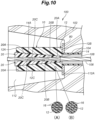
- Embodiment 7 of the prestressed concrete 100 will now be described with reference to Figure 10 .
- the parts corresponding to those in Figure 2 are denoted by the same reference numerals as the reference numerals in Figure 2 , and the description thereof will be omitted.
- the anchoring device 10 is mounted to each of the two ends of the concrete block 102 after molding and curing.
- a recess 112 having a truncated conical shape and opened to outside is molded at each of the two longitudinal end portions of the concrete block 102.
- Each recess 112 has an axial length greater than that of the anchoring device 10.
- a bottom surface 112A of each recess 112 forms a part of a substantial outer end surface of the concrete block 102.
- the anchoring device 10 is mounted to the concrete block 102 such that the inner end 12B of the barrel member 12 contacts the bottom surface 112A of the recess 112 via a patch plate 80 and the outer peripheral surface 12C of the barrel member 12 is exposed to outside.
- the entirety of the barrel member 12 is disposed in the recess 112.
- the anchoring devices 10 give a tension to the cable 106, whereby each anchoring device 10 is fixed to the concrete block 102 with the inner end 12B of the barrel member 12 being pressed against the patch plate 80 due to the tension.
- the prestressed concrete 100 of this embodiment allows for easy maintenance such as replacement of the anchoring device 10.
- recess 112 may be filled with mortar, asphalt, resin, or the like after arrangement of the anchoring device 10.
- the anchoring device 10 applied to the other embodiment shown in Figure 10 is not limited to the anchoring device 10 of Embodiment 1 and may be the anchoring device 10 of any of Embodiments 2 to 6.
- the barrel member 12 and the wedge member 20 may be composed of material other than resin, such as mortar, that is resistant to oxidation and corrosion.
- the barrel member 12 of Embodiments 2, 3, 5 and 6 may be made of resin containing no fibers.
- the wedge member 20, the spiral restraint body 60, and the annular restraint body 70 may be composed of material other than resin, such as titanium, that is resistant to oxidation and corrosion.
- the number of the wedge members 20 is not limited to two, and may be three or more.
- the wire may be a rod having flexibility.
- the anchoring device 10 is not limited to the one whose entirety is embedded in the concrete block 102, and may be adapted such that only a part on the side of the inner end 12B of the barrel member 12 is embedded in the concrete block 102 over a predetermined axial length.
Landscapes
- Engineering & Computer Science (AREA)
- Architecture (AREA)
- Civil Engineering (AREA)
- Structural Engineering (AREA)
- Reinforcement Elements For Buildings (AREA)
- Moulding By Coating Moulds (AREA)
Applications Claiming Priority (2)
| Application Number | Priority Date | Filing Date | Title |
|---|---|---|---|
| JP2020208553 | 2020-12-16 | ||
| PCT/JP2021/045668 WO2022131174A1 (ja) | 2020-12-16 | 2021-12-10 | 定着具及びプレストレスコンクリート |
Publications (2)
| Publication Number | Publication Date |
|---|---|
| EP4265863A1 true EP4265863A1 (de) | 2023-10-25 |
| EP4265863A4 EP4265863A4 (de) | 2024-11-06 |
Family
ID=82057806
Family Applications (1)
| Application Number | Title | Priority Date | Filing Date |
|---|---|---|---|
| EP21906536.4A Pending EP4265863A4 (de) | 2020-12-16 | 2021-12-10 | Befestigungselement und spannbeton |
Country Status (4)
| Country | Link |
|---|---|
| US (1) | US20240093494A1 (de) |
| EP (1) | EP4265863A4 (de) |
| JP (1) | JP7818529B2 (de) |
| WO (1) | WO2022131174A1 (de) |
Families Citing this family (3)
| Publication number | Priority date | Publication date | Assignee | Title |
|---|---|---|---|---|
| CN115262547B (zh) * | 2022-08-24 | 2024-06-28 | 铁科院(深圳)特种工程有限公司 | 基于装配式锚固结构的边坡防护网施工方法 |
| IT202300003774A1 (it) * | 2023-03-02 | 2024-09-02 | Sireg Geotech S R L | Testa per tirante |
| US12054947B1 (en) * | 2024-01-08 | 2024-08-06 | King Faisal University | Multi-layer wedge anchorage for FRP plates and FRP tendons |
Family Cites Families (74)
| Publication number | Priority date | Publication date | Assignee | Title |
|---|---|---|---|---|
| US1643110A (en) * | 1924-08-11 | 1927-09-20 | American Cable Co Inc | Attachment for wire rope and process for producing the same |
| US2042090A (en) * | 1933-07-29 | 1936-05-26 | Northern Malleable Iron Compan | Cable clamp |
| US2270240A (en) * | 1939-08-26 | 1942-01-20 | Freyssinet Eugene | Anchoring of tensioned cables in concrete constructions |
| US2303394A (en) * | 1940-02-21 | 1942-12-01 | Schorer Herman | Prestressing reinforced concrete |
| US2618147A (en) * | 1941-09-30 | 1952-11-18 | Freyssinet Eugene | Means anchoring tensioned cable for prestressed concrete |
| US2677956A (en) * | 1950-11-13 | 1954-05-11 | Schorer Corp | Prestressing and reinforcing apparatus for concrete structures |
| US2751660A (en) * | 1951-02-03 | 1956-06-26 | Nakonz Walter | Method of pre-stressing reinforced concrete structural elements |
| US2783024A (en) * | 1953-05-12 | 1957-02-26 | Lee Donovan Henry | Bar gripping means for use in the production of prestressed concrete |
| US3045305A (en) * | 1954-01-28 | 1962-07-24 | Concrete Technology Corp | Concrete prestressing cable grip |
| US2941394A (en) * | 1955-04-22 | 1960-06-21 | Fred H Brandt | Reinforcing and tensioning members for concrete structures |
| US2934935A (en) * | 1956-01-20 | 1960-05-03 | Holzmann Philipp Ag | Cast tensioning head for anchoring tensioning members, preferably for prestressed concrete |
| US2935299A (en) * | 1957-12-30 | 1960-05-03 | Jansen Gerhart | Clamp nut apparatus |
| GB894964A (en) * | 1958-10-06 | 1962-04-26 | Cufflin Holdings Ltd | Improvements in or relating to prestressed concrete |
| GB887605A (en) * | 1959-07-15 | 1962-01-17 | Cable Covers Ltd | Improvements in and relating to stressed concrete structures |
| US3091897A (en) * | 1959-08-19 | 1963-06-04 | Superior Concrete Accessories | Cable hold-down anchor device |
| US3106803A (en) * | 1960-08-09 | 1963-10-15 | Richmond Screw Anchor Co Inc | Supports for pre-stressing strands in concrete construction |
| US3286419A (en) * | 1963-12-26 | 1966-11-22 | Superior Concrete Accessories | Sectional hold-down anchor device |
| US3300922A (en) * | 1964-06-09 | 1967-01-31 | Heilmann & Littmann Bau Ag | Anchor assembly for prestressed concrete structures |
| US3425177A (en) * | 1966-09-23 | 1969-02-04 | Messrs Heilmann & Littman Bau | Fixed anchorage for concrete prestressing method with subsequent attachment |
| US3408783A (en) * | 1967-12-28 | 1968-11-05 | Edward K. Rice | Anchorage for post-stressed concrete structures |
| US3795949A (en) * | 1968-11-06 | 1974-03-12 | Pre Stress Pioneers Ltd | Post-stressing of reinforced concrete structures |
| US3948010A (en) * | 1971-12-17 | 1976-04-06 | Sonneville Roger P | Reinforcing device for an element of prestressed concrete |
| US3999418A (en) * | 1974-01-25 | 1976-12-28 | Juan Coll Morell | Method of making a tapered wedge |
| DE7508587U (de) * | 1975-03-18 | 1976-09-16 | Intercontinentale-Technik Gmbh, 8000 Muenchen | Endverankerung fuer spannelemente |
| DE2753112C3 (de) * | 1977-11-29 | 1981-01-22 | Dyckerhoff & Widmann Ag, 8000 Muenchen | Verankerung eines gespannten Zugglieds für große Belastungen in einem Betonbauteil, z.B. eines Schrägseils einer Schrägseilbrücke |
| US4309033A (en) * | 1979-09-19 | 1982-01-05 | Amf Incorporated | Clamping apparatus |
| DE8002045U1 (de) * | 1980-01-26 | 1980-04-30 | Dyckerhoff & Widmann Ag, 8000 Muenchen | Wiedergewinnbares schalungsteil fuer den verankerungsbereich eines spannglieds in einem betonbauteil |
| KR880002391Y1 (ko) * | 1985-06-25 | 1988-07-02 | 오용환 | 프레스트레스 콘크리트 강선 정착용 암콘 |
| GB2197360A (en) * | 1986-11-14 | 1988-05-18 | Pc Bridge Co Ltd | Prestressed concrete articles |
| US4837995A (en) * | 1987-05-13 | 1989-06-13 | Mitsubishi Mining And Cement Co., Ltd. | Anchoring device for a tension member of prestressed concrete |
| JPH0625457B2 (ja) * | 1987-11-02 | 1994-04-06 | 三菱マテリアル株式会社 | プレストレストコンクリート用定着具及び定着方法 |
| FR2648846B1 (fr) * | 1989-06-27 | 1991-09-20 | Chaize Alain | Dispositif de blocage pour armature allongee sous tension |
| EP0438383B1 (de) * | 1990-01-19 | 1993-05-26 | VSL International AG | Vorgespannte Betonauskleidung in einem Druckstollen |
| JPH0438354A (ja) * | 1990-06-01 | 1992-02-07 | Kajima Corp | Frpロッドの緊張方法 |
| US5043033A (en) * | 1991-01-28 | 1991-08-27 | Fyfe Edward R | Process of improving the strength of existing concrete support columns |
| EP0568667B1 (de) * | 1991-11-26 | 1996-09-11 | VSL International AG | Spannverankerung für spannglieder in einem bauwerksteil |
| DE4209265A1 (de) * | 1991-12-21 | 1993-06-24 | Dyckerhoff & Widmann Ag | Vorrichtung zur verankerung eines stabfoermigen zugglieds aus faserverbundwerkstoff |
| US5218810A (en) * | 1992-02-25 | 1993-06-15 | Hexcel Corporation | Fabric reinforced concrete columns |
| DE59306005D1 (de) * | 1992-03-24 | 1997-05-07 | Vsl Int Ag | Kraftübertragungskörper für eine Verankerung |
| US5326410A (en) * | 1993-03-25 | 1994-07-05 | Timber Products, Inc. | Method for reinforcing structural supports and reinforced structural supports |
| US5802788A (en) * | 1994-02-22 | 1998-09-08 | Kabushiki Kaisha Komatsu Seisakusho Komatsu Plastics Industry Co., Ltd. | Fixing device for tensioning member for prestressed concrete |
| DE4433847C2 (de) * | 1994-09-22 | 1997-09-25 | Dyckerhoff & Widmann Ag | Verfahren zum Einbringen einer Vergußmasse in einen Hohlraum |
| US5657595A (en) * | 1995-06-29 | 1997-08-19 | Hexcel-Fyfe Co., L.L.C. | Fabric reinforced beam and column connections |
| US5816759A (en) | 1997-05-08 | 1998-10-06 | Illinois Tool Works Inc. | Expansion anchor and method therefor |
| JPH11210163A (ja) | 1998-01-28 | 1999-08-03 | Ps:Kk | Frp緊張材の定着具 |
| ES2285752T3 (es) * | 1998-02-09 | 2007-11-16 | Vsl International Ag | Procedimiento de ejecuccion de un anclaje, pieza de anclaje y elemento de tension para este objeto. |
| DE19833332C1 (de) * | 1998-07-24 | 1999-12-16 | Dyckerhoff & Widmann Ag | Korrosionsgeschütztes Stahlzugglied |
| US6481102B1 (en) * | 1999-12-02 | 2002-11-19 | Tommie D. Hill | Attachment devices, systems, and methods for a tendon, rod, or other elongated member |
| DE10113283A1 (de) * | 2001-03-06 | 2003-01-23 | Scherer Josef | Bauteil oder Bauwerksteil mit Kernteil und Faser-Tragelement |
| US6560939B2 (en) * | 2001-03-19 | 2003-05-13 | Felix L. Sorkin | Intermediate anchor and intermediate anchorage system for a post-tension system |
| EP1396321A4 (de) * | 2001-05-24 | 2006-04-05 | Japan Science & Tech Agency | Verfahren zur herstellung von spannbeton |
| US6679024B2 (en) * | 2002-02-26 | 2004-01-20 | Kjell L. Dahl | High strength grouted pipe coupler |
| AT412564B (de) * | 2003-12-22 | 2005-04-25 | Burtscher Stefan L Dipl Ing Dr | Keilverankerung für vorgespannte und/oder belastete zugelemente |
| US7621085B2 (en) * | 2005-01-03 | 2009-11-24 | Commins Alfred D | Racheting take-up device |
| JP4558517B2 (ja) * | 2005-01-12 | 2010-10-06 | 成卓 岩熊 | 超電導コイル |
| US20060201083A1 (en) * | 2005-03-11 | 2006-09-14 | Hayes Speciality Machining, Ltd | Tensioning anchor suitable for blind-hole tendon anchoring and tendon repair |
| US7304243B2 (en) * | 2005-07-22 | 2007-12-04 | Connector Products, Inc. | Cable connector |
| US7819388B2 (en) * | 2006-01-17 | 2010-10-26 | Mccallion James P | Tendon gripping device |
| JP5217054B2 (ja) * | 2007-03-02 | 2013-06-19 | 住友電工スチールワイヤー株式会社 | ストランド |
| US7905066B2 (en) * | 2007-04-06 | 2011-03-15 | Simpson Strong-Tie Co., Inc. | Automatic take-up device and in-line coupler |
| DE102009016693A1 (de) * | 2009-04-07 | 2010-10-14 | Thomas Friedrich | Ankerhülse für die Verankerung von vorgespannten Bewehrungselementen |
| US8425143B2 (en) * | 2009-08-12 | 2013-04-23 | Tokyo Rope Manufacturing Co., Ltd. | End anchoring structure and method for fiber-reinforced plastic filament body |
| ES2399863B1 (es) * | 2010-03-08 | 2014-02-11 | Acciona Windpower S.A. | Torre de aerogenerador y procedimiento de montaje de la misma |
| EP2420622A1 (de) * | 2010-08-18 | 2012-02-22 | Sika Technology AG | Vorrichtung zur Krafteinleitung in Zugglieder aus faserverstärkten Kunststoff-Flachbandlamellen |
| JP6022997B2 (ja) * | 2013-05-09 | 2016-11-09 | 三井住友建設株式会社 | 緊張材の定着体及び引張部材 |
| WO2015049395A1 (es) * | 2013-10-03 | 2015-04-09 | Acciona Infraestructuras, S.A. | Dispositivo retenedor |
| JP6342345B2 (ja) * | 2015-02-09 | 2018-06-13 | 三菱重工業株式会社 | 金属製ナノコイルの製造方法 |
| JP6546829B2 (ja) | 2015-10-19 | 2019-07-17 | 槌屋ティスコ株式会社 | 繊維強化樹脂ロッド及びその製造方法 |
| JP6770783B2 (ja) | 2016-08-08 | 2020-10-21 | 三井住友建設株式会社 | 中間定着具及び中間定着具の装着方法 |
| AU2017363837C1 (en) * | 2016-11-23 | 2023-12-14 | Pultrall Inc. | Method and system for producing a reinforcing bar, and resulting reinforcing bar |
| FR3062862B1 (fr) * | 2017-02-13 | 2019-04-05 | Soletanche Freyssinet | Dispositif d'ancrage pour paroi moulee precontrainte |
| ES2926319T3 (es) * | 2018-06-25 | 2022-10-25 | Carbo Link Ag | Manguito de anclaje, sistema de anclaje y procedimiento para la fabricación de aquél |
| KR101989167B1 (ko) * | 2018-11-23 | 2019-09-30 | 한국건설기술연구원 | 이중웨브를 이용한 중공형 합성보 및 그 시공방법 |
| BR112023000602A2 (pt) * | 2020-07-15 | 2023-03-28 | Ccl Stressing Int Ltd | Âncoras de pós-tensionamento de concreto |
-
2021
- 2021-12-10 WO PCT/JP2021/045668 patent/WO2022131174A1/ja not_active Ceased
- 2021-12-10 US US18/257,174 patent/US20240093494A1/en active Pending
- 2021-12-10 EP EP21906536.4A patent/EP4265863A4/de active Pending
- 2021-12-10 JP JP2022569958A patent/JP7818529B2/ja active Active
Also Published As
| Publication number | Publication date |
|---|---|
| EP4265863A4 (de) | 2024-11-06 |
| TW202237952A (zh) | 2022-10-01 |
| JP7818529B2 (ja) | 2026-02-20 |
| JPWO2022131174A1 (de) | 2022-06-23 |
| US20240093494A1 (en) | 2024-03-21 |
| WO2022131174A1 (ja) | 2022-06-23 |
Similar Documents
| Publication | Publication Date | Title |
|---|---|---|
| EP4265863A1 (de) | Befestigungselement und spannbeton | |
| CN109797910B (zh) | 一种frp筋锚固用夹片、加工方法及锚固方法 | |
| US4442646A (en) | Device for anchoring tensioning elements | |
| US20200157818A1 (en) | Reinforcement anchoring device | |
| JP2019027270A (ja) | 連続繊維補強より線の定着具 | |
| WO2016203649A1 (ja) | 連続繊維補強材緊張装置、連続繊維補強材の緊張方法及びくさび体 | |
| RU2178082C2 (ru) | Канатный анкер | |
| EP2417310B1 (de) | Bewehrungselement für einen konstruktionsbetonbau | |
| AU2015348333B2 (en) | A reinforcement system and a method of reinforcing a structure with a tendon | |
| TWI922545B (zh) | 錨固件及預力混凝土 | |
| JP2014214457A (ja) | 耐荷体及びグラウンドアンカー | |
| JP5103784B2 (ja) | コンクリート構造物及びプレストレストコンクリート工法 | |
| JP5922993B2 (ja) | 複数微細ひび割れ型繊維補強セメント複合材料を用いた構造体およびライニング方法 | |
| JP7478683B2 (ja) | 定着構造、及び定着構造の形成方法 | |
| EP0291601A1 (de) | Verfahren zur Herstellung von Verankerungsvorrichtungen für mehrere Elemente für Spannbeton | |
| JP2005264484A (ja) | 超高曲靭性pc柱状物 | |
| JP2007070895A (ja) | プレストレス導入用合成構造定着体及びそれを用いた構造物 | |
| JPH04296512A (ja) | 繊維補強材 | |
| EP0044883B1 (de) | Vorrichtung zum Verankern von Metalldrähten an Strukturen mit Hilfe von Epoxyharz | |
| JP3121424U (ja) | 炭素繊維コンクリート補強筋 | |
| JP6770784B2 (ja) | コンクリート部材の接合構造及びコンクリート部材の接合方法 | |
| JP2696939B2 (ja) | プレストレストコンクリート用定着体 | |
| US20220049499A1 (en) | Composite rebar for use with quick connect coupling | |
| JPH01290415A (ja) | 繊維強化樹脂複合体製緊張材 | |
| RU129961U1 (ru) | Композиционная арматура |
Legal Events
| Date | Code | Title | Description |
|---|---|---|---|
| STAA | Information on the status of an ep patent application or granted ep patent |
Free format text: STATUS: THE INTERNATIONAL PUBLICATION HAS BEEN MADE |
|
| PUAI | Public reference made under article 153(3) epc to a published international application that has entered the european phase |
Free format text: ORIGINAL CODE: 0009012 |
|
| STAA | Information on the status of an ep patent application or granted ep patent |
Free format text: STATUS: REQUEST FOR EXAMINATION WAS MADE |
|
| 17P | Request for examination filed |
Effective date: 20230717 |
|
| AK | Designated contracting states |
Kind code of ref document: A1 Designated state(s): AL AT BE BG CH CY CZ DE DK EE ES FI FR GB GR HR HU IE IS IT LI LT LU LV MC MK MT NL NO PL PT RO RS SE SI SK SM TR |
|
| DAV | Request for validation of the european patent (deleted) | ||
| DAX | Request for extension of the european patent (deleted) | ||
| A4 | Supplementary search report drawn up and despatched |
Effective date: 20241004 |
|
| RIC1 | Information provided on ipc code assigned before grant |
Ipc: E04C 5/12 20060101ALI20240927BHEP Ipc: E04C 5/08 20060101AFI20240927BHEP |
|
| GRAP | Despatch of communication of intention to grant a patent |
Free format text: ORIGINAL CODE: EPIDOSNIGR1 |
|
| STAA | Information on the status of an ep patent application or granted ep patent |
Free format text: STATUS: GRANT OF PATENT IS INTENDED |