EP4265926A1 - Vorrichtung zum verbinden von bühnenbeschlägen - Google Patents
Vorrichtung zum verbinden von bühnenbeschlägen Download PDFInfo
- Publication number
- EP4265926A1 EP4265926A1 EP23168390.5A EP23168390A EP4265926A1 EP 4265926 A1 EP4265926 A1 EP 4265926A1 EP 23168390 A EP23168390 A EP 23168390A EP 4265926 A1 EP4265926 A1 EP 4265926A1
- Authority
- EP
- European Patent Office
- Prior art keywords
- fixing pin
- shank
- socket
- section
- hole
- Prior art date
- Legal status (The legal status is an assumption and is not a legal conclusion. Google has not performed a legal analysis and makes no representation as to the accuracy of the status listed.)
- Granted
Links
Images


Classifications
-
- B—PERFORMING OPERATIONS; TRANSPORTING
- B25—HAND TOOLS; PORTABLE POWER-DRIVEN TOOLS; MANIPULATORS
- B25G—HANDLES FOR HAND IMPLEMENTS
- B25G1/00—Handle constructions
- B25G1/06—Handle constructions reversible or adjustable for position
- B25G1/063—Handle constructions reversible or adjustable for position for screwdrivers, wrenches or spanners
- B25G1/066—Handle constructions reversible or adjustable for position for screwdrivers, wrenches or spanners the grip itself being angularly adjustable
-
- F—MECHANICAL ENGINEERING; LIGHTING; HEATING; WEAPONS; BLASTING
- F16—ENGINEERING ELEMENTS AND UNITS; GENERAL MEASURES FOR PRODUCING AND MAINTAINING EFFECTIVE FUNCTIONING OF MACHINES OR INSTALLATIONS; THERMAL INSULATION IN GENERAL
- F16B—DEVICES FOR FASTENING OR SECURING CONSTRUCTIONAL ELEMENTS OR MACHINE PARTS TOGETHER, e.g. NAILS, BOLTS, CIRCLIPS, CLAMPS, CLIPS OR WEDGES; JOINTS OR JOINTING
- F16B21/00—Means for preventing relative axial movement of a pin, spigot, shaft or the like and a member surrounding it; Stud-and-socket releasable fastenings
- F16B21/10—Means for preventing relative axial movement of a pin, spigot, shaft or the like and a member surrounding it; Stud-and-socket releasable fastenings by separate parts
- F16B21/12—Means for preventing relative axial movement of a pin, spigot, shaft or the like and a member surrounding it; Stud-and-socket releasable fastenings by separate parts with locking-pins or split-pins thrust into holes
-
- F—MECHANICAL ENGINEERING; LIGHTING; HEATING; WEAPONS; BLASTING
- F16—ENGINEERING ELEMENTS AND UNITS; GENERAL MEASURES FOR PRODUCING AND MAINTAINING EFFECTIVE FUNCTIONING OF MACHINES OR INSTALLATIONS; THERMAL INSULATION IN GENERAL
- F16B—DEVICES FOR FASTENING OR SECURING CONSTRUCTIONAL ELEMENTS OR MACHINE PARTS TOGETHER, e.g. NAILS, BOLTS, CIRCLIPS, CLAMPS, CLIPS OR WEDGES; JOINTS OR JOINTING
- F16B21/00—Means for preventing relative axial movement of a pin, spigot, shaft or the like and a member surrounding it; Stud-and-socket releasable fastenings
- F16B21/02—Releasable fastening devices locking by rotation
- F16B21/04—Releasable fastening devices locking by rotation with bayonet catch
-
- F—MECHANICAL ENGINEERING; LIGHTING; HEATING; WEAPONS; BLASTING
- F16—ENGINEERING ELEMENTS AND UNITS; GENERAL MEASURES FOR PRODUCING AND MAINTAINING EFFECTIVE FUNCTIONING OF MACHINES OR INSTALLATIONS; THERMAL INSULATION IN GENERAL
- F16B—DEVICES FOR FASTENING OR SECURING CONSTRUCTIONAL ELEMENTS OR MACHINE PARTS TOGETHER, e.g. NAILS, BOLTS, CIRCLIPS, CLAMPS, CLIPS OR WEDGES; JOINTS OR JOINTING
- F16B21/00—Means for preventing relative axial movement of a pin, spigot, shaft or the like and a member surrounding it; Stud-and-socket releasable fastenings
- F16B21/06—Releasable fastening devices with snap-action
- F16B21/065—Releasable fastening devices with snap-action with an additional locking element
-
- F—MECHANICAL ENGINEERING; LIGHTING; HEATING; WEAPONS; BLASTING
- F16—ENGINEERING ELEMENTS AND UNITS; GENERAL MEASURES FOR PRODUCING AND MAINTAINING EFFECTIVE FUNCTIONING OF MACHINES OR INSTALLATIONS; THERMAL INSULATION IN GENERAL
- F16B—DEVICES FOR FASTENING OR SECURING CONSTRUCTIONAL ELEMENTS OR MACHINE PARTS TOGETHER, e.g. NAILS, BOLTS, CIRCLIPS, CLAMPS, CLIPS OR WEDGES; JOINTS OR JOINTING
- F16B21/00—Means for preventing relative axial movement of a pin, spigot, shaft or the like and a member surrounding it; Stud-and-socket releasable fastenings
- F16B21/06—Releasable fastening devices with snap-action
- F16B21/07—Releasable fastening devices with snap-action in which the socket has a resilient part
- F16B21/071—Releasable fastening devices with snap-action in which the socket has a resilient part the socket being integrally formed with a component to be fasted, e.g. a sheet, plate or strip
-
- F—MECHANICAL ENGINEERING; LIGHTING; HEATING; WEAPONS; BLASTING
- F16—ENGINEERING ELEMENTS AND UNITS; GENERAL MEASURES FOR PRODUCING AND MAINTAINING EFFECTIVE FUNCTIONING OF MACHINES OR INSTALLATIONS; THERMAL INSULATION IN GENERAL
- F16B—DEVICES FOR FASTENING OR SECURING CONSTRUCTIONAL ELEMENTS OR MACHINE PARTS TOGETHER, e.g. NAILS, BOLTS, CIRCLIPS, CLAMPS, CLIPS OR WEDGES; JOINTS OR JOINTING
- F16B21/00—Means for preventing relative axial movement of a pin, spigot, shaft or the like and a member surrounding it; Stud-and-socket releasable fastenings
- F16B21/06—Releasable fastening devices with snap-action
- F16B21/08—Releasable fastening devices with snap-action in which the stud, pin, or spigot has a resilient part
- F16B21/086—Releasable fastening devices with snap-action in which the stud, pin, or spigot has a resilient part the shank of the stud, pin or spigot having elevations, ribs, fins or prongs intended for deformation or tilting predominantly in a direction perpendicular to the direction of insertion
-
- F—MECHANICAL ENGINEERING; LIGHTING; HEATING; WEAPONS; BLASTING
- F16—ENGINEERING ELEMENTS AND UNITS; GENERAL MEASURES FOR PRODUCING AND MAINTAINING EFFECTIVE FUNCTIONING OF MACHINES OR INSTALLATIONS; THERMAL INSULATION IN GENERAL
- F16B—DEVICES FOR FASTENING OR SECURING CONSTRUCTIONAL ELEMENTS OR MACHINE PARTS TOGETHER, e.g. NAILS, BOLTS, CIRCLIPS, CLAMPS, CLIPS OR WEDGES; JOINTS OR JOINTING
- F16B21/00—Means for preventing relative axial movement of a pin, spigot, shaft or the like and a member surrounding it; Stud-and-socket releasable fastenings
- F16B21/06—Releasable fastening devices with snap-action
- F16B21/08—Releasable fastening devices with snap-action in which the stud, pin, or spigot has a resilient part
- F16B21/088—Releasable fastening devices with snap-action in which the stud, pin, or spigot has a resilient part the stud, pin or spigot being integrally formed with the component to be fastened, e.g. forming part of the sheet, plate or strip
-
- F—MECHANICAL ENGINEERING; LIGHTING; HEATING; WEAPONS; BLASTING
- F16—ENGINEERING ELEMENTS AND UNITS; GENERAL MEASURES FOR PRODUCING AND MAINTAINING EFFECTIVE FUNCTIONING OF MACHINES OR INSTALLATIONS; THERMAL INSULATION IN GENERAL
- F16B—DEVICES FOR FASTENING OR SECURING CONSTRUCTIONAL ELEMENTS OR MACHINE PARTS TOGETHER, e.g. NAILS, BOLTS, CIRCLIPS, CLAMPS, CLIPS OR WEDGES; JOINTS OR JOINTING
- F16B21/00—Means for preventing relative axial movement of a pin, spigot, shaft or the like and a member surrounding it; Stud-and-socket releasable fastenings
- F16B21/10—Means for preventing relative axial movement of a pin, spigot, shaft or the like and a member surrounding it; Stud-and-socket releasable fastenings by separate parts
- F16B21/16—Means for preventing relative axial movement of a pin, spigot, shaft or the like and a member surrounding it; Stud-and-socket releasable fastenings by separate parts with grooves or notches in the pin or shaft
-
- F—MECHANICAL ENGINEERING; LIGHTING; HEATING; WEAPONS; BLASTING
- F21—LIGHTING
- F21V—FUNCTIONAL FEATURES OR DETAILS OF LIGHTING DEVICES OR SYSTEMS THEREOF; STRUCTURAL COMBINATIONS OF LIGHTING DEVICES WITH OTHER ARTICLES, NOT OTHERWISE PROVIDED FOR
- F21V21/00—Supporting, suspending, or attaching arrangements for lighting devices; Hand grips
- F21V21/005—Supporting, suspending, or attaching arrangements for lighting devices; Hand grips for several lighting devices in an end-to-end arrangement, i.e. light tracks
-
- F—MECHANICAL ENGINEERING; LIGHTING; HEATING; WEAPONS; BLASTING
- F21—LIGHTING
- F21W—INDEXING SCHEME ASSOCIATED WITH SUBCLASSES F21K, F21L, F21S and F21V, RELATING TO USES OR APPLICATIONS OF LIGHTING DEVICES OR SYSTEMS
- F21W2131/00—Use or application of lighting devices or systems not provided for in codes F21W2102/00-F21W2121/00
- F21W2131/40—Lighting for industrial, commercial, recreational or military use
- F21W2131/406—Lighting for industrial, commercial, recreational or military use for theatres, stages or film studios
Definitions
- the subject of the present invention is a connecting device for stage fixtures, in particular for connecting stage devices or stage accessories.
- the device is used to connect fixtures under difficult conditions with insufficient lighting and at difficult-to-access locations.
- the device can also be used to connect devices under similar conditions outside the stage as well.
- a fixing pin which includes a pin, a coaxial sleeve, and a pressing spring arranged inside the sleeve which positions the fixing pin in a closed position.
- a retracting handle for unlocking the pin is attached to the other end of the pin.
- the fixing pin cooperates with a housing that has a hole and with an element that is being connected which includes fixing holes that are matched to the fixing pin.
- CN208731120 discloses a manual bicycle device for adjusting the height of an electric bicycle saddle.
- the solution includes an adjustable saddle with a seat on a vertical tube in a vehicle frame, and a round pull pin including a spring, a set screw in the vertical tube of the seat to form a swivelling connection.
- This is a typical application of the fixing pin; the disadvantage of such a solution is the necessity to hit the fixing hole, which is not an issue in the case of adjusting the height of the saddle.
- the use of the fixing pin cooperating with the hole in the connecting tube is ineffective.
- Stage fixtures can be connected in any direction, including also upwardly, and not only in line with the direction of gravity.
- the user must aim the pin into the hole to lock the two elements which need to be precisely matched together in two planes, and any dirt or mismatches may cause a risk of incorrect securing of the connection, and under difficult lighting conditions and/or limited manoeuvrability, the user may not be able to verify the correct position of the fixing pin. This creates a serious risk of accident for people using the stage due to an accidental disconnection of stage fixtures.
- the saddle is fixedly attached to the connecting tube, i.e. one element has a fixedly attached fastener. There is often a need for stage fixtures to come together by being butted together, without gaps. Then, unlike in the case of the saddle, aligning the fixing hole with the fixing pin may pose difficulties, especially when the fastener is invisible, as it is completely hidden in a socket.
- the connecting device solves the problem of combining the fixing pin with the fixing hole, while at the same time providing an easy-to-operate, dirt-resistant device that allows to connect the elements without gaps in between, to pull together the elements that are being connected, to fix the orientation relative to each other of the elements that are being connected and that, thanks to increased reliability, provides a secure connection for stage fixtures, in particular when working under difficult lighting conditions and with limited access to the device.
- the connecting device for stage fixtures includes a connecting shank and at least one fixing pin connected to a housing of at least one connecting socket, wherein the connecting shank is detachably connected to the at least one connecting socket and protected against disconnection by the at least one fixing pin.
- the connecting device is characterized in that the connecting shank with a substantially longitudinal shape has a cross-section with at least two axes of symmetry. This prevents the shank from rotating about its longitudinal axis.
- the connecting shank includes at least one fixing slot with a cross-section similar to the letter U, and the fixing slot extends over the entire transverse circumference of the connecting shank.
- the cross-section of the connecting shank has two axes of symmetry, more preferably three axes of symmetry, and most preferably four axes of symmetry.
- the connecting shank has a square cross-section.
- the connecting shank has at least one end contoured in a conical shape. This facilitates connecting the socket by means of the connecting shank, as the surface of the cone raises the fixing pin when the connecting shank is inserted into the connecting socket, and then it causes the connection to snap when the fixing pin encounters the first fixing slot.
- the at least one fixing slot is formed at the location where the end of the connecting shank that is contoured in a conical shape connects with the portion of the connecting shank that has a cross-section with at least two axes of symmetry.
- a wall of the fixing slot which is located closer to the end of the connecting shank, is inclined to the longitudinal axis of the connecting shank such that the width of the slot narrows towards the longitudinal axis of the connecting shank. Thanks to this, the connecting shank causes an outer edge of one connecting socket to be pressed to a corresponding other edge of the other connecting socket or a housing to which the connecting shank is mounted.
- the fixing pin includes a locking protection against unintentional extraction.
- the locking protection against unintentional extraction includes a contoured spring plate as well as a working slot and a locking socket in the housing of the connecting socket, wherein the contoured spring plate is movably connected to the fixing pin, and in a secured position it is locked in the locking socket, while in an unlocked position it is arranged in the working slot.
- the contour of the spring plate includes five consecutive sections, wherein four sections are situated at a right angle relative to each other to form a stepped structure.
- the first section includes a hole for the end of the fixing pin which connects to a retracting handle of the fixing pin, wherein the spring plate is mounted movably about the axis of the fixing pin, while at the same time the spring plate is mounted immovably in relation to the longitudinal axis of the fixing pin.
- the fifth section of the spring plate is inclined at an acute angle of 30 to 60 degrees relative to the fourth section.
- the working gap and the locking socket in the housing of the connecting socket form a hole which has a shape similar to one eighth of a circular segment with a center in the axis of the fixing pin.
- the hole is extended by a hole with a diameter corresponding to the diameter of the sleeve of the fixing pin, and on straight line segments of the edges it is extended by a half of the width of the spring plate.
- the hole additionally includes a sickle-shaped projection with arcuate concentric edges connected by a straight edge which is parallel to the opposite straight line segment of the edge of the hole.
- a triangular locking projection is located on the edge of the hole that is spaced the farthest away from the axis of the fixing pin.
- the hole is loosely fitted to a locking plate.
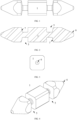
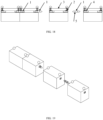
- Fig. 1 shows a side view of the connecting shank
- Fig. 2 shows a sectional view of the connecting shank along its axis
- Fig. 3 shows a front view of the connecting shank
- Fig. 4 shows an axonometric view of the connecting shank
- Fig. 5 schematically shows a connection of two connecting sockets via the connecting shank
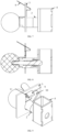
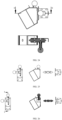
- Fig. 6 schematically shows the fixing pin
- Figs. 7-8 show the fixing pin with the locking protection
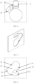
- Figs. 10-12 show the working gap and the locking socket in the housing of the connecting device
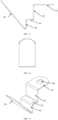
- Figs. 13-17 show, in different views, an element of the locking protection - the spring plate
- Figs. 18-19 illustrate the device's principle of operation when connecting stage fixtures
- Figs. 20-22 show embodiments of the device in housings of stage fixtures
- Figs. 23-26 show exemplary housings in a connected and disconnected state, together with their sectional views.
- the connecting device for stage fixtures includes a connecting shank 1 ( Figs. 1-4 ) and two fixing pins 2.1 and 2.2 connected to housings 3.1 and 3.2 of connecting sockets 4.1 and 4.2 ( Fig. 5 ).
- the housing 3 (3.1, 3.2) of the connecting socket 4 (4.1, 4.2) is fixedly integrated with a housing of a stage fixture;
- Fig. 5 shows the connecting sockets 4, 4.1 and 4.2.
- the housing 3 of the connecting socket 4 may be connected to a housing 44 ( Figs. 20-22 ) of a stage fixture outside its outline, at any angle to the plane of the housing of the fixture - by way of example, 45 degrees.
- the connecting shank 1 is detachably connected to the two connecting sockets 4.1 and 4.2, one of the sockets 4.1 is located in the housing 3.1 inside a first stage fixture, by way of example, in the housing of a first lamp, and the other socket is located in the housing 3.2 inside a second stage fixture, by way of example, in the housing of a second lamp.
- the connecting shank 1 is protected against disconnection by the first fixing pin 2.1 of the first lamp and the second fixing pin 2.2 of the second lamp.
- the connecting shank 1 has a longitudinal shape with a square cross-section.
- the connecting shank 1 also includes two fixing slots 5.1 and 5.2 with a cross-section similar to the letter U. Each slot 5.1 and 5.2 comprises the entire transverse circumference of the connecting shank 1.
- the connecting shank 1 has ends contoured in conical shapes which transition into a square cross-section. This enables to fix relative to each other the planes of the housings of stage fixtures - by way of example, lamps - with an accuracy to a 90-degree rotation relative to the axis of the connecting shank 1 and the axes of the connecting sockets 4.1 and 4.2.
- the fixing slots 5.1 and 5.2 are located in the connecting shank 1 at the location where the ends 6 of the connecting shaft 1 that are contoured in a conical shape transition into a square cross-section.
- One of the walls 7 of the fixing slot 5 (5.1, 5.2), which is located closer to the end 6 of the connecting shank 1, is inclined to the longitudinal axis of the connecting shank 1 such that the width of the slot 5 narrows as it gets closer to the longitudinal axis of the connecting shank 1 ( Figs. 1-5 ). Thanks to this, the connecting shank causes an outer edge of the first connecting socket 4.1 to be pressed to a corresponding other edge of the second connecting socket 4.2 when the fixing pins 2.1 and 2.2 are inserted into the slots 5.1 and 5.2.
- the connecting shank when the connecting shank has only one end 6, and at the other end it is fixedly attached to a housing of a stage fixture (by way of example, a lamp), the shape of the slot 5 causes the edge of the connecting socket to be pressed to the housing of the stage fixture adjacent to the location where the connecting shank 1 connects with that housing.
- the fixing pin 2 includes a locking protection 8 against unintentional extraction.
- the locking protection 8 against unintentional extraction includes a contoured spring plate 9 as well as a working slot 10 and a locking socket 11 in the housing 3 of the connecting socket 4, wherein the contoured spring plate 9 is movably connected to the fixing pin 2, and in a secured position it is locked in the locking socket 11, while in an unlocked position it is in the working slot 10.
- Figs. 20-21 show the spring plate 9 in two positions; in Fig. 20 , in a locked position, the spring plate 9 rests in the locking socket 11, and in Fig. 21 , in an unlocked position, it rests in the working slot 10 and may be extracted out of it together with the fixing pin 2.
- the housing 3 of the connecting socket 4 may have an open or closed form; it is sufficient for a front wall to include a hole of the connecting socket 4, and an adjacent wall including an outer portion of the fixing pin 2 is perpendicular thereto.
- the fixing pin 2 is swivellingly movable in an axis perpendicular to the axis of the connecting socket 4, as in typical applications of the fixing pins.
- the wall of the housing 3 that includes the outer portion of the fixing pin 2 also includes the working slot 10 and the locking socket 11 which form a hole with a shape similar to the letter L, wherein the axis of the longer portion passes through the axis of the fixing pin 2.
- the shape of a hole in the housing 3 which comprises the working slot 10 and the locking socket 11.
- This hole has a shape similar to 1/8 of a circular segment with a center overlapping with the axis of the fixing pin 2 ( Figs. 10-12 ).
- the radius of the segment corresponds to the length of the spring plate 9 at the height of its third section which extends substantially parallel to the wall of the housing 3 on its inner side ( Figs. 7 -9 ).
- the hole is extended by a round hole with a radius corresponding to the diameter of the sleeve of the fixing pin 2 that has a center in the axis of this pin.
- the hole 12 includes a sickle-shaped projection 13 that blocks the movement of the plate and the fixing pin 2 connected therewith when the spring plate 9 is in the locked position.
- the sickle-shaped projection 13 includes two edges constituting two concentric line segments of arcs that have a center in the axis of the fixing pin 2 and are connected by a straight edge which is parallel to the opposite edge of the hole 12 in the housing 3 and is located at a distance corresponding to the width of the spring plate 9.
- the edge of the hole that is spaced the farthest apart from the axis of the fixing pin includes a triangular locking projection 14 which locks the spring plate 9 in the locking socket; to release it, a free end of the plate has to be pressed towards the fixing pin 2 and the plate has to be rotated towards the working slot 10 with a substantially rectangular outline.
- small projections 15 are located that fix the position of the portion of the spring plate 9 that is closer to the axis of the fixing pin 2 in the working slot 10 or in the locking socket 11.
- the locking socket 11 forming a lower portion of the letter L includes a locking projection with a shape similar to a triangular tooth on which the spring plate 9 rests in the locked position. Compressing the spring plate 9 enables to rotate it to a position in the working slot 10 in which the movement of the fixing pin 2 is not blocked, thus it is possible to disconnect the connecting shank 1 from the connecting socket 4.
- the contour of the spring plate 9 is shown illustratively in Figs. 13 - 17 .
- the plate includes five sections, wherein four sections are situated at a right angle relative to each other, and additionally the first section includes a hole for the end of the fixing pin which connects to a retracting handle of the fixing pin ( Figs. 15 - 17 ).
- the last, fifth segment of the spring plate 9 is inclined at an acute angle - by way of example, 45 degrees - relative to the fourth section.
- Such a shape of the plate is matched to the working slot 10 and the locking socket 11 and prevents the fixing pin from being raised in the locked position.
Landscapes
- Engineering & Computer Science (AREA)
- General Engineering & Computer Science (AREA)
- Mechanical Engineering (AREA)
- Snaps, Bayonet Connections, Set Pins, And Snap Rings (AREA)
- Pivots And Pivotal Connections (AREA)
Applications Claiming Priority (1)
| Application Number | Priority Date | Filing Date | Title |
|---|---|---|---|
| PL440998A PL440998A1 (pl) | 2022-04-22 | 2022-04-22 | Urządzenie do łączenia osprzętu scenicznego |
Publications (2)
| Publication Number | Publication Date |
|---|---|
| EP4265926A1 true EP4265926A1 (de) | 2023-10-25 |
| EP4265926B1 EP4265926B1 (de) | 2026-03-04 |
Family
ID=88069682
Family Applications (1)
| Application Number | Title | Priority Date | Filing Date |
|---|---|---|---|
| EP23168390.5A Active EP4265926B1 (de) | 2022-04-22 | 2023-04-18 | Vorrichtung zum verbinden von bühnenausstattung |
Country Status (2)
| Country | Link |
|---|---|
| EP (1) | EP4265926B1 (de) |
| PL (1) | PL440998A1 (de) |
Citations (4)
| Publication number | Priority date | Publication date | Assignee | Title |
|---|---|---|---|---|
| US3980408A (en) * | 1974-04-30 | 1976-09-14 | Jachmann Rolf Dieter | Construction element |
| JPS5659319U (de) * | 1980-10-01 | 1981-05-21 | ||
| US20040055244A1 (en) * | 2002-06-21 | 2004-03-25 | Gimpel Dixon S. | Framework connection system |
| CN208731120U (zh) | 2018-05-24 | 2019-04-12 | 上海保真电子商务有限公司 | 一种自行车及电动自行车车座高度手动调节装置 |
Family Cites Families (5)
| Publication number | Priority date | Publication date | Assignee | Title |
|---|---|---|---|---|
| US4848956A (en) * | 1986-02-21 | 1989-07-18 | Burn Tubes Limited | Securing means |
| RO116791B1 (ro) * | 1992-07-13 | 2001-06-29 | Friedman Mark | Dispozitiv telescopic de manipulare |
| GB0118429D0 (en) * | 2001-07-28 | 2001-09-19 | Sperling Ltd | Display support system |
| US8439593B2 (en) * | 2009-11-10 | 2013-05-14 | Imds Corporation | Quarter turn locking mechanism |
| US20160008970A1 (en) * | 2014-07-14 | 2016-01-14 | Yu-Hui Ho | Socket Tool |
-
2022
- 2022-04-22 PL PL440998A patent/PL440998A1/pl unknown
-
2023
- 2023-04-18 EP EP23168390.5A patent/EP4265926B1/de active Active
Patent Citations (4)
| Publication number | Priority date | Publication date | Assignee | Title |
|---|---|---|---|---|
| US3980408A (en) * | 1974-04-30 | 1976-09-14 | Jachmann Rolf Dieter | Construction element |
| JPS5659319U (de) * | 1980-10-01 | 1981-05-21 | ||
| US20040055244A1 (en) * | 2002-06-21 | 2004-03-25 | Gimpel Dixon S. | Framework connection system |
| CN208731120U (zh) | 2018-05-24 | 2019-04-12 | 上海保真电子商务有限公司 | 一种自行车及电动自行车车座高度手动调节装置 |
Also Published As
| Publication number | Publication date |
|---|---|
| EP4265926B1 (de) | 2026-03-04 |
| PL440998A1 (pl) | 2023-10-23 |
Similar Documents
| Publication | Publication Date | Title |
|---|---|---|
| US7628382B2 (en) | Nail extractor, moulding remover and pry bar tool with indexable head | |
| US9778425B2 (en) | Fiber optic connector and pin keeper with field changeable guide pins | |
| CN106972333B (zh) | 用于等离子弧焊炬的连接器组件 | |
| US5475997A (en) | Lock assembly | |
| US4403885A (en) | Cable connector | |
| US3728879A (en) | Heavy cable shackle padlock | |
| US11609384B2 (en) | Light blocking shutter for optical fiber adapter | |
| CN105579762A (zh) | 快速安装连接器 | |
| EP4265926A1 (de) | Vorrichtung zum verbinden von bühnenbeschlägen | |
| US6935871B2 (en) | Electrical cord plug lock | |
| CN111720393A (zh) | 快装快拆结构及展示架 | |
| US20130167599A1 (en) | Combination lock with reduced axial length | |
| EP1251603A2 (de) | Fassung für Lampen mit Zweistiftsockel | |
| US7237457B2 (en) | Screw feeder adapter for a power screwdriver | |
| TWM524384U (zh) | 易安裝之防火門鎖具 | |
| US6986678B1 (en) | Lockable electrical connector | |
| CN211646604U (zh) | 一种用于嵌入式水箱的快速连接结构 | |
| US10944212B1 (en) | Power connector with anti-disengaging mechanism | |
| US20260078608A1 (en) | Locking mechanism and rotating key | |
| CN223786946U (zh) | 角度控制器 | |
| CN105150092B (zh) | 适用于砂光机的底板 | |
| US20100150647A1 (en) | Pipe fixture | |
| AU2006100407A4 (en) | Screw Feeder Adapter for a Power Screwdriver | |
| EP1536091A1 (de) | Motorradschloss mit mehrstufiger Verriegelung bzw. Entriegelung | |
| CN107690239B (zh) | 具有可拆式把手的电子装置 |
Legal Events
| Date | Code | Title | Description |
|---|---|---|---|
| STAA | Information on the status of an ep patent application or granted ep patent |
Free format text: STATUS: REQUEST FOR EXAMINATION WAS MADE |
|
| PUAI | Public reference made under article 153(3) epc to a published international application that has entered the european phase |
Free format text: ORIGINAL CODE: 0009012 |
|
| 17P | Request for examination filed |
Effective date: 20230510 |
|
| AK | Designated contracting states |
Kind code of ref document: A1 Designated state(s): AL AT BE BG CH CY CZ DE DK EE ES FI FR GB GR HR HU IE IS IT LI LT LU LV MC ME MK MT NL NO PL PT RO RS SE SI SK SM TR |
|
| GRAP | Despatch of communication of intention to grant a patent |
Free format text: ORIGINAL CODE: EPIDOSNIGR1 |
|
| STAA | Information on the status of an ep patent application or granted ep patent |
Free format text: STATUS: GRANT OF PATENT IS INTENDED |
|
| RIC1 | Information provided on ipc code assigned before grant |
Ipc: F16B 21/16 20060101AFI20250925BHEP Ipc: F16B 21/12 20060101ALI20250925BHEP Ipc: F21V 21/005 20060101ALI20250925BHEP Ipc: F21W 131/406 20060101ALN20250925BHEP |
|
| INTG | Intention to grant announced |
Effective date: 20251014 |
|
| GRAS | Grant fee paid |
Free format text: ORIGINAL CODE: EPIDOSNIGR3 |
|
| GRAA | (expected) grant |
Free format text: ORIGINAL CODE: 0009210 |
|
| STAA | Information on the status of an ep patent application or granted ep patent |
Free format text: STATUS: THE PATENT HAS BEEN GRANTED |
|
| AK | Designated contracting states |
Kind code of ref document: B1 Designated state(s): AL AT BE BG CH CY CZ DE DK EE ES FI FR GB GR HR HU IE IS IT LI LT LU LV MC ME MK MT NL NO PL PT RO RS SE SI SK SM TR |
|
| REG | Reference to a national code |
Ref country code: CH Ref legal event code: F10 Free format text: ST27 STATUS EVENT CODE: U-0-0-F10-F00 (AS PROVIDED BY THE NATIONAL OFFICE) Effective date: 20260304 Ref country code: GB Ref legal event code: FG4D |
|
| REG | Reference to a national code |
Ref country code: IE Ref legal event code: FG4D |
|
| REG | Reference to a national code |
Ref country code: DE Ref legal event code: R096 Ref document number: 602023012840 Country of ref document: DE |