EP4265997A1 - Griff für einen mit einem griffkörper und einem griffkörper gebildeten griffbogen und bogen dafür - Google Patents
Griff für einen mit einem griffkörper und einem griffkörper gebildeten griffbogen und bogen dafür Download PDFInfo
- Publication number
- EP4265997A1 EP4265997A1 EP23167526.5A EP23167526A EP4265997A1 EP 4265997 A1 EP4265997 A1 EP 4265997A1 EP 23167526 A EP23167526 A EP 23167526A EP 4265997 A1 EP4265997 A1 EP 4265997A1
- Authority
- EP
- European Patent Office
- Prior art keywords
- grip
- handle body
- intended
- handle
- arm
- Prior art date
- Legal status (The legal status is an assumption and is not a legal conclusion. Google has not performed a legal analysis and makes no representation as to the accuracy of the status listed.)
- Pending
Links
- 210000003813 thumb Anatomy 0.000 claims abstract description 9
- 210000003811 finger Anatomy 0.000 claims description 10
- 239000003381 stabilizer Substances 0.000 claims description 7
- 238000010304 firing Methods 0.000 claims description 4
- 230000000149 penetrating effect Effects 0.000 claims description 2
- 208000031968 Cadaver Diseases 0.000 description 15
- 210000003414 extremity Anatomy 0.000 description 5
- 239000000463 material Substances 0.000 description 4
- 230000000694 effects Effects 0.000 description 3
- 230000000977 initiatory effect Effects 0.000 description 3
- XAGFODPZIPBFFR-UHFFFAOYSA-N aluminium Chemical compound [Al] XAGFODPZIPBFFR-UHFFFAOYSA-N 0.000 description 2
- 229910052782 aluminium Inorganic materials 0.000 description 2
- 238000003780 insertion Methods 0.000 description 2
- 230000037431 insertion Effects 0.000 description 2
- 230000002441 reversible effect Effects 0.000 description 2
- 239000002023 wood Substances 0.000 description 2
- 229920000049 Carbon (fiber) Polymers 0.000 description 1
- 239000004962 Polyamide-imide Substances 0.000 description 1
- 239000006096 absorbing agent Substances 0.000 description 1
- 239000004760 aramid Substances 0.000 description 1
- 229920003235 aromatic polyamide Polymers 0.000 description 1
- 239000004917 carbon fiber Substances 0.000 description 1
- 239000012141 concentrate Substances 0.000 description 1
- 238000005034 decoration Methods 0.000 description 1
- 239000012530 fluid Substances 0.000 description 1
- 238000002347 injection Methods 0.000 description 1
- 239000007924 injection Substances 0.000 description 1
- 239000004973 liquid crystal related substance Substances 0.000 description 1
- 238000004519 manufacturing process Methods 0.000 description 1
- 239000007769 metal material Substances 0.000 description 1
- 239000000203 mixture Substances 0.000 description 1
- 230000007935 neutral effect Effects 0.000 description 1
- 239000003973 paint Substances 0.000 description 1
- 239000004033 plastic Substances 0.000 description 1
- 229920003023 plastic Polymers 0.000 description 1
- 229920002401 polyacrylamide Polymers 0.000 description 1
- 229920002312 polyamide-imide Polymers 0.000 description 1
- 239000002861 polymer material Substances 0.000 description 1
- 230000035807 sensation Effects 0.000 description 1
- 230000035939 shock Effects 0.000 description 1
- 230000005236 sound signal Effects 0.000 description 1
- 230000006641 stabilisation Effects 0.000 description 1
- 238000011105 stabilization Methods 0.000 description 1
- 230000008719 thickening Effects 0.000 description 1
- 230000007704 transition Effects 0.000 description 1
- 230000003313 weakening effect Effects 0.000 description 1
Images


Classifications
-
- F—MECHANICAL ENGINEERING; LIGHTING; HEATING; WEAPONS; BLASTING
- F41—WEAPONS
- F41B—WEAPONS FOR PROJECTING MISSILES WITHOUT USE OF EXPLOSIVE OR COMBUSTIBLE PROPELLANT CHARGE; WEAPONS NOT OTHERWISE PROVIDED FOR
- F41B5/00—Bows; Crossbows
- F41B5/14—Details of bows; Accessories for arc shooting
- F41B5/1403—Details of bows
- F41B5/1426—Bow stabilisers or vibration dampers
-
- F—MECHANICAL ENGINEERING; LIGHTING; HEATING; WEAPONS; BLASTING
- F41—WEAPONS
- F41B—WEAPONS FOR PROJECTING MISSILES WITHOUT USE OF EXPLOSIVE OR COMBUSTIBLE PROPELLANT CHARGE; WEAPONS NOT OTHERWISE PROVIDED FOR
- F41B5/00—Bows; Crossbows
- F41B5/14—Details of bows; Accessories for arc shooting
- F41B5/1403—Details of bows
- F41B5/1438—Buttons
-
- F—MECHANICAL ENGINEERING; LIGHTING; HEATING; WEAPONS; BLASTING
- F41—WEAPONS
- F41A—FUNCTIONAL FEATURES OR DETAILS COMMON TO BOTH SMALLARMS AND ORDNANCE, e.g. CANNONS; MOUNTINGS FOR SMALLARMS OR ORDNANCE
- F41A35/00—Accessories or details not otherwise provided for
- F41A35/06—Adaptation of guns to both right and left hand use
Definitions
- the invention relates to the field of archery practiced in clubs or for leisure.
- the invention can advantageously be used indoors or outdoors and is suitable for archers of all levels.
- a bow is made up of a handle, at the ends of which extend two branches on which a string is stretched.
- bow grips differ if the archer is left-handed or right-handed.
- a left-hander uses a handle adapted for a left-hander while a right-hander uses a handle adapted for a right-hander.
- first category mainly used for leisure, in outdoor activities and/or intended for beginner archers.
- This first category is generally made in a single block in materials resistant to impacts and bad weather.
- the patent EP 1 070 933 describes a bow whose handle and branches are made in one piece.
- the handle has an ergonomic shape in its center intended to accommodate an archer's hand. To do this, two distinct bow shapes must be made to cover the needs of left-handed and right-handed archers.
- Another category of bows intended for more experienced archers practicing club archery, includes an additional part called a "grip" and intended to be fixed in the center of a handle body, so as to facilitate the grip of the bow and to increase the comfort and sensations of the archer.
- the combination of the grip on the handle body thus makes it possible to form an arc handle.
- a first form, intended for left-handers, comprises a left-handed handle body and a left-handed grip and a second form, intended for right-handers, comprises a right-handed handle body and a right-handed grip.
- the patent US 4,966,124 describes a grip, in the shape of an elongated “U”, intended to fit onto the rear of the edge of a handle body.
- the technical problem that the invention aims to solve is therefore to produce a bow that can be adapted to a left-hander and a right-hander, while allowing experienced archers to use such a bow without feeling a drop in comfort or performance. shooting.
- Each arm has a recess forming a shooting window and means for fixing the grip.
- the handle body has, for its part, a plane of symmetry so that the archer can select one of the arms to fix the grip and the other arm to form the shooting window.
- the selection of each arm is carried out by tilting 180° around an axis of the plane of symmetry, in order to obtain a handle suitable for a left-handed or a right-handed person.
- the design of the grip body allows an archer to adapt the bow to his guiding hand in a limited number of steps and without having to disassemble either the limbs of the grip body or the bow string. . Simply disassemble the grip, turn the bow over and reassemble the grip on the opposite arm.
- the grip fixing means correspond to at least one hole opening into the recess of each arm; the at least one through hole being intended to accommodate at least one screw penetrating the grip.
- the archer can carry out a simple screwing operation.
- the grip is thus less likely to move or separate from the handle body when the bow undergoes twisting and/or deformation forces linked to shooting an arrow.
- the grip fixing means are also configured to fix an arrow rest and/or a Berger button in the recess in the arm forming the shooting window.
- a “Berger button” or “compensator button” is composed of an internal spring which presses on the arrow tube.
- the Berger button acts as a shock absorber for the arrow when it is propelled and reduces its undulations.
- a right-handed or left-handed archer can use the grip support means opposite to those already occupied by a grip to attach additional grip accessories. way to improve your shooting experience. This therefore makes it possible to adapt the bow to the level of the archer by adding or not accessories for compensation and/or stabilization of the shot.
- the grip support means correspond to two through holes opening onto the side faces of the handle body.
- the grip can be fixed laterally on the handle body, unlike the grips of the state of the art, which fit onto the rear face of the handle body.
- the grips can therefore be one-piece, unlike the grips of the state of the art, which have a U shape.
- the one-piece grips are thus generally more resistant to deformation or breakage.
- each arm has second means for fixing a clicker and/or a viewfinder.
- a clicker corresponds to an accessory producing a sound signal indicating to an archer that he must release his arrow.
- Such an accessory allows an archer to make his shooting movement more fluid.
- the fact of using a single type of fixing means for several different accessories makes it possible to reduce the production costs of the handle body.
- the invention also relates to a grip intended to be mounted on a handle body as described above.
- the upper part has a protrusion on its first side face, intended to form, with the recess of an arm of said handle body, the firing window.
- Such a grip is also a part which is easy to handle.
- fixing can be carried out by placing the grip on one side of the handle body and aligning the grip fixing means on the handle body.
- the grip fixing means correspond to at least one threaded blind hole configured to receive at least one fixing screw.
- the grip also includes a threaded tube configured to accommodate a stabilizer located at a lower part of a rear face of the grip.
- the stabilizer can be integrated on the bow handle without having to make a recess in the handle body, which would have the effect of weakening the handle body which is subjected to strong torsional stresses when the bow is drawn and when the arrow is released.
- the invention also relates to an ambidextrous bow grip comprising a grip body and a grip as previously described.
- the invention finally relates to an ambidextrous bow comprising a handle as described above, at the ends of which two branches are mounted, and a rope stretched at the ends of the two branches.
- a bow comprising such a handle body and such a grip is very versatile because it can adapt to all levels, from a beginner archer who does not use accessories to an experienced archer who practices shooting. archery in competition and who uses numerous accessories such as a stabilizer, a Berger button, a sight and/or a clicker.
- the handle body 1000 seen from its rear face 100, has a central part 12 in the shape of a “C”, hatched on the figure 1 , comprising a notch 10 allowing the archer's thumb to be supported.
- the opposite face 11 is preferably curved to allow the central part 12 to have a substantially constant thickness, typically between 2 and 5 centimeters.
- two arms 13 extend vertically over a length of between 50 and 70 centimeters and a substantially constant thickness, typically between 2 and 5 centimeters.
- a first edge of the arms 13, located on the same side as the notch 10, has a substantially rectilinear appearance.
- the opposite edge 15 has an arcuate appearance linked to the presence of a recess 16 on the side face 101. This recess 16 is intended to form a shooting window in which the archer can position his arrow 17 and aim at a target.
- the end of the arms 13 closest to the central part 12 has two holes 22 with a diameter of between 0.2 and 1 centimeter located at a distance of between 1 and 5 centimeters from the central part 12 and at a distance of between 3 and 7 centimeters from the center of the central part 12.
- the two holes are spaced from each other by 0.5 to 3 centimeters and by 1 to 3 centimeters from the lateral ends of the side faces 101 and 102.
- the two holes 22 are positioned on each arm 13, symmetrically with respect to the central part 12. Alternatively, the arms 13 may have only one hole or three holes without changing the invention.
- a countersink of enlarged diameter present at the ends of the holes 22, makes it possible to accommodate the heads of the screws. These then do not protrude and do not hinder the archer's grip.
- the holes 22 may be intended to attach a grip 2000 and/or accessories such as an arrow rest or a shepherd's button.
- the end of the arms 13 extending opposite the central part 12 is wider, typically between 5 and 7 centimeters and forms substantially flat surfaces intended to receive the branches of the arc.
- the arms 13 are configured to receive a particular type of branch.
- the arms 13 can be configured to receive initiation branches or even branches arch belonging to the standardized ILF system (for “ International Limb Fitting System ” in English literature, corresponding to a system for fixing the branches). An archer can thus choose the technicality of his branches according to his level.
- the two opposite ends of the arms 13 are generally identical.
- the upper arm 13 of the handle body 1000 is shown with an ILF branch attachment system
- the lower arm 13 of the handle body 1000 is shown with an attachment system of initiation branches.
- the system for fixing an initiation branch is provided with a substantially rectangular footprint 18A making it possible to position the branch to be fixed.
- the imprint thus extends from the end of the arm 13, over a length of between 7 and 10 centimeters.
- the impression 18A also includes an opening 25 with a diameter of between 0.5 and 1 centimeter comprising a thread.
- the opening 25 is intended to receive a screw 26 for fixing the branches, also called a tiller.
- the end of the branch having a through opening is aligned with the recess 18A, then the fixing screw 26 passes through the branch and is inserted into the opening 25, generally blind.
- the cavity 18B has a rounded end, a hole 19 and an oblong-shaped opening 20.
- the oblong-shaped opening of the branch ILF is aligned with the hole 19 of the cavity 18B and the hole of the ILF branch is aligned with the oblong-shaped opening 20 of the cavity 18B.
- the ILF branch and the recess 18B are then screwed together using a fixing screw 21.
- the hole 19 can be through and a locking counter nut can be used to block the rotation of the fixing screw 21.
- the attachment system can be adapted to accommodate both ILF limbs and conventional training limbs.
- the arms 13 also include holes 23, 24 of smaller diameter, typically between 0.1 and 0.7 centimeters. These holes 23, 24 are intended for attaching other accessories such as a viewfinder or a clicker.
- the front face can also include blind openings allowing a clicker extension to be inserted.
- the handle body 1000 is formed from wood, carbon fibers or a metallic material, typically aluminum, and covered with a layer of paint and/or decorations.
- the range can include several handle bodies of several sizes, typically a 21 inch handle, a 23 inch handle and a 25 inch handle.
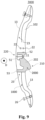
- a grip 2000 has a one-piece shape with a height of between 10 and 20 centimeters comprising an upper part 220 intended to ensure the positioning of the thumb and at least the index finger of the archer and a lower part 210 intended for mounting the grip 2000 on an arm 13 of the handle body 1000.
- the upper part 220 includes a recess 51, provided on a first face 202 of the grip 2000, against which the archer's thumb is positioned.
- the opposite face 201 of the recess 51 is intended to receive the archer's index finger.
- the opposite face 201 also includes, at its upper end, a protrusion 52 projecting, perpendicular to the length of the grip 2000, over a length of between 0.5 and 1.5 centimeters.
- the protrusion 52 is intended to form, associated with the handle body 1000, a firing window.
- the lower part 210 has a curved portion on the opposite face 201 to the recess 51.
- the curved portion ensures the positioning of the archer's other fingers, while the first face 202 is intended to receive the palm of the archer. 'archer.
- the lower part 210 advantageously comprises a hollow tubular portion 53 preferably having an internal thread projecting towards the front face of the grip 2000. This hollow tubular portion 53 is intended for the insertion of a stabilizer, either by screwing, or by force insertion.
- the stabilizer can be independent of the grip 2000 and fit on the bow in both right-handed and left-handed configurations.
- the opposite face 201 also has two holes 54 with a diameter of between 0.2 and 1 centimeter.
- the two holes are 0.5 to 3 centimeters apart from each other.
- These holes 54 are intended for fixing the grip 2000 to the handle body 3000.
- a countersink of enlarged diameter present at the ends of the holes 54, makes it possible to accommodate the head of the fixing screws. These then do not protrude and do not hinder the archer's grip.
- the grip 2000 is formed by a single injection operation.
- the material used to form the grip 2000 is preferably a plastic material, a polymer material such as aromatic polyamide, preferably chosen, alone or as a mixture, from the group comprising polyacrylamides, liquid crystals, polyamide imides.
- the grip 2000 can be made of wood or aluminum.
- a right-hander In order to mount its 3000 bow grip, a right-hander will hold the 1000 grip body in the configuration of the Figure 7 , that is to say he will hold the grip body 1000 in his left hand in order to tighten the bowstring with his right hand.
- a left-handed person will hold the grip body 1000 in his right hand in order to tighten the bowstring with his left hand.
- the archer rotates the handle body 1000 by 180° around the axis D so as to reverse the arms 13.
- the arm 13 initially located at the bottom thus finds itself at the top and vice versa.
- the archer also orients the central part 12 of the handle body 1000 so that his thumb rests in the notch 10.
- the grip 2000 can be mounted on the handle body 1000 by pressing the grip 2000 against a side face 201, 202 of the handle body 1000.
- the grip 2000 is attached to the side face 102 of the handle body 1000.
- the first side face 201 of the grip 2000 comprises a portion 55 at least partially covering the notch 10 of the central part 12 of the handle body 1000.
- the thickness of the portion 55 being increasingly thin, typically going from 0.5 centimeter to 0.01 centimeter, in order to improve the transition between the grip 2000 and the handle body 1000 and not to create a bump or extra thickness which would deteriorate the grip of the the handle 3000.
- the second side face 202 of the grip 2000 includes a recess 51 making it possible to leave visible at least a fraction of the convex part 11 of the central part 12 of the grip body 1000.
- the archer's index finger comes directly into contact with the grip body 1000 when gripping the grip 3000. This prevents the grip area from thickening, which would deteriorate the archer's grip.
- the lower part 210 of the grip 2000 extends over the side face 101 of the lower arm 13 of the handle body 1000.
- the combination of the handle body 1000 and the lower part 210 of the grip 2000 forms an extra thickness making it possible to support the fingers .
- the total width of the finger positioning area is between 5 and 7 centimeters.
- the grip 2000 also extends towards the rear face of the handle body 1000, extending therefrom by approximately 2 to 5 centimeters.
- the grip has through holes 22 so that the archer can screw from a side face 101, 102 of the handle body 100 into the grip 2000, arranged on the face opposite side 101,102 of the handle body 1000.
- the holes 22 can be blind holes. The archer can thus screw from a side face of the grip 2000, into the handle body 1000, arranged on the opposite side face of the grip 2000.
- the screws can pass through both the grip 2000 and the handle body 1000.
- the invention makes it possible to produce a bow that can be adapted to a left-hander and a right-hander, while allowing experienced archers to use such a bow without feeling a drop in comfort or shooting performance thanks to the presence numerous sites for receiving accessories such as a stabilizer, a Berger button, a viewfinder and/or a clicker.
Landscapes
- Engineering & Computer Science (AREA)
- General Engineering & Computer Science (AREA)
- Toys (AREA)
- Food-Manufacturing Devices (AREA)
Applications Claiming Priority (1)
| Application Number | Priority Date | Filing Date | Title |
|---|---|---|---|
| FR2203650A FR3134886A1 (fr) | 2022-04-20 | 2022-04-20 | Poignee d’arc ambidextre formee d’un grip et d’un corps de poignee et arc associe |
Publications (1)
| Publication Number | Publication Date |
|---|---|
| EP4265997A1 true EP4265997A1 (de) | 2023-10-25 |
Family
ID=82483205
Family Applications (1)
| Application Number | Title | Priority Date | Filing Date |
|---|---|---|---|
| EP23167526.5A Pending EP4265997A1 (de) | 2022-04-20 | 2023-04-12 | Griff für einen mit einem griffkörper und einem griffkörper gebildeten griffbogen und bogen dafür |
Country Status (2)
| Country | Link |
|---|---|
| EP (1) | EP4265997A1 (de) |
| FR (1) | FR3134886A1 (de) |
Citations (6)
| Publication number | Priority date | Publication date | Assignee | Title |
|---|---|---|---|---|
| US2294052A (en) * | 1941-09-19 | 1942-08-25 | Roger B Springer | Archery bow |
| US3804072A (en) * | 1970-02-21 | 1974-04-16 | Nippon Musical Instruments Mfg | Combination of archery bow with single or plural stabilizers |
| US4966124A (en) | 1988-04-18 | 1990-10-30 | Michael R. Burling | Grip assembly for archery bow |
| US5697358A (en) | 1996-01-11 | 1997-12-16 | Campisi; Curtis | Reversible riser for archery bow enabling left and right hand use |
| US5762060A (en) * | 1994-10-31 | 1998-06-09 | Browning | Handle riser for archery bows |
| EP1070933A1 (de) | 1999-07-19 | 2001-01-24 | Plastiques Paillard | Recurve-Bogen |
-
2022
- 2022-04-20 FR FR2203650A patent/FR3134886A1/fr active Pending
-
2023
- 2023-04-12 EP EP23167526.5A patent/EP4265997A1/de active Pending
Patent Citations (6)
| Publication number | Priority date | Publication date | Assignee | Title |
|---|---|---|---|---|
| US2294052A (en) * | 1941-09-19 | 1942-08-25 | Roger B Springer | Archery bow |
| US3804072A (en) * | 1970-02-21 | 1974-04-16 | Nippon Musical Instruments Mfg | Combination of archery bow with single or plural stabilizers |
| US4966124A (en) | 1988-04-18 | 1990-10-30 | Michael R. Burling | Grip assembly for archery bow |
| US5762060A (en) * | 1994-10-31 | 1998-06-09 | Browning | Handle riser for archery bows |
| US5697358A (en) | 1996-01-11 | 1997-12-16 | Campisi; Curtis | Reversible riser for archery bow enabling left and right hand use |
| EP1070933A1 (de) | 1999-07-19 | 2001-01-24 | Plastiques Paillard | Recurve-Bogen |
Also Published As
| Publication number | Publication date |
|---|---|
| FR3134886A1 (fr) | 2023-10-27 |
Similar Documents
| Publication | Publication Date | Title |
|---|---|---|
| EP2541188B1 (de) | Schaft mit Kolbenboden für eine Schulterwaffe | |
| FR2657531A1 (fr) | Tete de club de golf. | |
| FR2712197A1 (fr) | Série de clubs de golf. | |
| FR2692156A1 (fr) | Club pour la pratique du golf. | |
| EP2716333B1 (de) | Federballschläger | |
| EP0353174B1 (de) | Auseinandernehmbarer Sportbogen mit Schwingungsverhalten | |
| FR3134886A1 (fr) | Poignee d’arc ambidextre formee d’un grip et d’un corps de poignee et arc associe | |
| EP0509032A1 (de) | Tennisschläger mit injektionserzeugtem schaft und dessen herstellungsverfahren | |
| EP2135807B1 (de) | Handgerät zum Anlegen von Dehnfolie | |
| EP4424392B1 (de) | Bodenstützvorrichtung mit einem stock und einer handschlaufe | |
| BE407745A (de) | ||
| EP2758137B1 (de) | Griff für badmintonschläger und zugehöriges herstellungsverfahren | |
| EP3894778B1 (de) | Gewehrkolben | |
| EP2490774A1 (de) | Überzugselement für einen schlägergriff, überzugsset, überzug und entsprechendes verfahren | |
| CA1167876A (fr) | Baton de hockey perfectionne | |
| EP1589313A2 (de) | Hilfsmittel für Jäger | |
| EP4294717B1 (de) | Griff für einen schaft des oar-wellentyps und oar mit solch einem griff | |
| FR2930170A1 (fr) | Support de balle de golf amovible. | |
| EP1557635B1 (de) | Satz von Bogenteilen für einen Sportbogen und Herstellungsverfahren für dieselben | |
| FR2580795A1 (fr) | Arc | |
| FR3162995A1 (fr) | Poignée de bâton de ski | |
| WO2020070449A1 (fr) | Poignee de baton amelioree | |
| FR2811419A1 (fr) | Arme pour le tir de precision | |
| FR3139894A1 (fr) | Crosse pour carabine de tir sportif de précision, en particulier pour la pratique du biathlon | |
| FR2685793A1 (fr) | Dispositif auto-bloquant et auto-guidant pour poignee. |
Legal Events
| Date | Code | Title | Description |
|---|---|---|---|
| STAA | Information on the status of an ep patent application or granted ep patent |
Free format text: STATUS: THE APPLICATION HAS BEEN PUBLISHED |
|
| PUAI | Public reference made under article 153(3) epc to a published international application that has entered the european phase |
Free format text: ORIGINAL CODE: 0009012 |
|
| AK | Designated contracting states |
Kind code of ref document: A1 Designated state(s): AL AT BE BG CH CY CZ DE DK EE ES FI FR GB GR HR HU IE IS IT LI LT LU LV MC ME MK MT NL NO PL PT RO RS SE SI SK SM TR |
|
| STAA | Information on the status of an ep patent application or granted ep patent |
Free format text: STATUS: REQUEST FOR EXAMINATION WAS MADE |
|
| 17P | Request for examination filed |
Effective date: 20240220 |
|
| RBV | Designated contracting states (corrected) |
Designated state(s): AL AT BE BG CH CY CZ DE DK EE ES FI FR GB GR HR HU IE IS IT LI LT LU LV MC ME MK MT NL NO PL PT RO RS SE SI SK SM TR |