EP4266038A1 - Biocapteur - Google Patents
Biocapteur Download PDFInfo
- Publication number
- EP4266038A1 EP4266038A1 EP23169187.4A EP23169187A EP4266038A1 EP 4266038 A1 EP4266038 A1 EP 4266038A1 EP 23169187 A EP23169187 A EP 23169187A EP 4266038 A1 EP4266038 A1 EP 4266038A1
- Authority
- EP
- European Patent Office
- Prior art keywords
- reagent layer
- reagent
- biosensor
- mean thickness
- layer
- Prior art date
- Legal status (The legal status is an assumption and is not a legal conclusion. Google has not performed a legal analysis and makes no representation as to the accuracy of the status listed.)
- Pending
Links
Images


Classifications
-
- G—PHYSICS
- G01—MEASURING; TESTING
- G01N—INVESTIGATING OR ANALYSING MATERIALS BY DETERMINING THEIR CHEMICAL OR PHYSICAL PROPERTIES
- G01N27/00—Investigating or analysing materials by the use of electric, electrochemical, or magnetic means
- G01N27/26—Investigating or analysing materials by the use of electric, electrochemical, or magnetic means by investigating electrochemical variables; by using electrolysis or electrophoresis
- G01N27/28—Electrolytic cell components
- G01N27/30—Electrodes, e.g. test electrodes; Half-cells
- G01N27/327—Biochemical electrodes, e.g. electrical or mechanical details for in vitro measurements
- G01N27/3271—Amperometric enzyme electrodes for analytes in body fluids, e.g. glucose in blood
- G01N27/3272—Test elements therefor, i.e. disposable laminated substrates with electrodes, reagent and channels
Definitions
- the present disclosure relates to a biosensor and a measuring method using the same.
- a biosensor is a molecular measuring device using a molecule recognition element of a detection unit in which a biological material, such as an enzyme, is arranged and a transducer (signal conversion device), such as electrodes.
- the biosensor is used for measuring various biological substances to be analyzed, such as glucose in a living body.
- the biosensor generally includes electrodes and a reagent layer mounted on the electrodes.
- a method for forming the reagent layer is a method of applying a reagent liquid containing an oxidoreductase, an electron transfer substance, and the like over the electrodes and drying the reagent liquid.
- Exemplary methods for applying a reagent liquid include the following: the dipping method, the dispenser method, screen process printing, offset printing, and ink-jet printing ( JP-A-2011-99693 , JP-A-H6(1994)-3317 , and JP-A-2017-520773 ).
- the present disclosure provides a biosensor that is capable of performing measurement with a high reproducibility and a measuring method using the same.
- the present disclosure relates to a biosensor that comprises a base material; a conductive part including two or more electrodes provided on a surface of the base material; and a reagent layer provided on at least a part of the conductive part; wherein the mean thickness of the reagent layer is 5 ⁇ m to 10 ⁇ m, and a mean thickness difference in the reagent layer calculated based on the following formula, that is a difference between a mean thickness of a peripheral part and a mean thickness of a central part in the reagent layer, is -6 ⁇ m to +5 ⁇ m.
- mean thickness difference mean thickness of peripheral part ⁇ mean thickness of central part
- the present disclosure relates to, as another aspect, a method for electrochemically measuring a measurement object in a sample, comprising bringing a sample into contact with a reagent layer of the biosensor of the present disclosure; applying a voltage across electrodes of the biosensor; and measuring an electric signal generated by the application of the voltage.
- a biosensor that is capable of performing measurement with a high reproducibility, and a measuring method using the same can be provided.
- a biosensor including a reagent layer that has the following characteristics can realize a high reproducibility: having a mean thickness of 5 ⁇ m to 10 ⁇ m; and having a mean thickness difference of -6 ⁇ m to +5 ⁇ m, that is a difference between a mean thickness of a peripheral part and a mean thickness of a central part in the reagent layer.
- the reagent layer has a mean thickness in the above-described range and a difference between mean thicknesses of the peripheral and central parts in the above-described range, the dissolution of a reagent occurring when a sample is supplied to the reagent layer becomes substantially uniform, which makes it possible to suppress irregularities in the reagent dissolution. Consequently, when measurement errors that can occur between biosensors (deviations of measurement results occurring between different biosensors when the known concentration of a component is measured) are reduced, the reproducibility is enhanced, according to estimation.
- the present disclosure is not limited to this mechanism.
- the present inventors found that irregularities in the concentration or amount of a reagent in a reagent layer cause irregularities in the dissolution of a reagent in the reagent layer and then lead to the deterioration of the reproducibility.
- the reagent layer is generally formed by applying a reagent liquid containing components, such as an oxidoreductase, an electron transfer substance, and the like and drying the reagent liquid.
- a reagent liquid When a reagent liquid is applied, precipitation occurs in peripheral parts of the reagent layer due to a concentration gradient that occurs in the process of drying, growing from crystals in the peripheral parts.
- Another method of forming a reagent layer by dispensing a single drop pf reagent liquid only is also known. In this case, however, the amount of the reagent is greater in the peripheral part, while the amount of the reagent is smaller in the center part, which causes irregularities in the concentrations or amounts of the components, such as an oxidoreductase in the reagent layer.
- JP-A-2011-99693 discloses a method of forming a reagent layer by spraying a reagent so that droplets thereof are separated from one another, in order to avoid the occurrence of deviation of the amount of an enzyme caused by union of droplets.
- JP-A-2011-99693 when the method is used for a biosensor in which a sufficient amount of a reagent has to be mounted within a limited range, there is the problem that a sufficient amount of a reagent cannot be mounted thereon.
- a reagent liquid containing reagent components such as an oxidoreductase and an electron transfer substance, are ejected at predetermined pitches. Droplets of the reagent liquid are ejected at a predetermined distance apart so that adjacent liquid droplets do not substantially merge with each other on a conductive part, and the liquid droplets are dried to form a droplet dots pattern. Then, the liquid droplets of the reagent liquid are repeatedly ejected on the dried droplet dots in the same manner as above, so that the reagent liquids are stacked and integrated, thereby forming a reagent layer.
- reagent liquid containing reagent components such as an oxidoreductase and an electron transfer substance
- the present disclosure relates to a biosensor that comprises a base material, a conductive part including two or more electrodes formed on a surface of the base material, and a reagent layer mounted on at least a part of the conductive part.
- the biosensor of the present disclosure has the following characteristics: the reagent layer has a mean thickness of 5 ⁇ m to 10 ⁇ m; and a mean thickness difference of -6 ⁇ m to +5 ⁇ m, that is a difference between a mean thickness of a peripheral part in the reagent layer and a mean thickness of a central part in the reagent layer.
- the measurement with a high reproducibility can be performed.
- lot-to-lot differences and within-lot differences can be reduced, which makes it possible to output a correct response-measured value, thereby providing an accurate value.
- the reagent layer has a mean thickness of 5 ⁇ m to 10 ⁇ m, the mean thickness of the reagent layer is above 5 ⁇ m, preferably 6 ⁇ m or more, 6.5 ⁇ m or more, or 7 ⁇ m or more, from the viewpoint of obtaining a higher reproducibility.
- the mean thickness of the reagent layer is 9.5 ⁇ m or less, preferably 9 ⁇ m or less, or 8.5 ⁇ m or less, from the same viewpoint.
- the mean thickness of the reagent layer can be measured and calculated by the method described in the Example. The measurement of the thickness of the reagent layer can be performed by, for example, measuring the thickness thereof along the center line directed along the transverse direction of the reagent layer (the position indicated by the arrow in FIG.
- FIG. 4 is a schematic diagram for explaining a method for measuring a mean thickness of the reagent layer, in which only the reagent layer is focused and shown.
- the reagent layer in the present disclosure refers to a layer of a reagent mounted in an area that is substantially involved in the measurement of an analysis object. Examples of the area that is substantially involved in the measurement of an analysis object include the inside of a flow channel in which a sample flows, in one or a plurality of embodiments.
- the difference between a mean thickness of a peripheral part and a mean thickness of a central part in the reagent layer is -6 ⁇ m to +5 ⁇ m.
- the difference between mean thicknesses of the peripheral and central parts is preferably -5 ⁇ m to +5 ⁇ m, -4 ⁇ m to +4 ⁇ m, -3 ⁇ m to +3 ⁇ m, -2 ⁇ m to +2 ⁇ m, or -1 ⁇ m to +1 ⁇ m, from the viewpoint of obtaining a higher reproducibility.
- the difference between mean thicknesses of the peripheral and central parts is preferably ⁇ m to +2.5 ⁇ m, -3 ⁇ m to +2 ⁇ m, or -3 ⁇ m to +1.5 ⁇ m.
- the difference between a mean thickness of a peripheral part and a mean thickness of a central part in the reagent layer can be calculated by the method described in the Example.
- the mean thickness of the peripheral part and the mean thickness of the central part in the reagent layer can be calculated using thicknesses measured in the same method as that used for the mean thickness of the reagent layer, as in the method described in the Example.
- the mean thickness of the central part in the reagent layer may also be assumed to be a mean value of thicknesses in a range with a width of 0.1 mm on each side in a transverse direction from a point of intersection of a transverse-direction center line and a longitudinal-direction center line of the reagent layer (a range with a width of 0.2 mm in total, for example, a range CE in FIG. 4 ).
- the reagent layer is mounted in the flow channel, the transverse direction of the reagent layer is a direction of a flow channel in which the sample flows, and the longitudinal direction of the reagent layer is a width direction of the biosensor that is orthogonal to the flow channel direction (for example, in the aspect illustrated in FIG.
- the mean thickness of the central part in the reagent layer can be paraphrased as a mean value of thicknesses in a range with a width of 0.1 mm on each of the upstream side and the downstream side from the point of intersection of the transverse-direction center line and the longitudinal-direction center line of the reagent layer (a range with a width of 0.2 mm in total).
- the mean thickness of the peripheral part in the reagent layer refers to a mean value of thicknesses in a range with a width of 0.1 mm from each end of the reagent layer in the transverse direction (for example, ranges EN1 and EN2 in FIG. 4 ).
- the mean thickness of the central part in the reagent layer refers to a mean value of thicknesses in a range with a width of a radius of 0.1 mm from the center of the reagent layer in the longitudinal direction of the biosensor.
- the mean thickness of the peripheral part refers to a mean value of thicknesses in a range with a width of 0.1 mm from the circumferential part, which is a mean value of thicknesses in a range with a width of 0.1 mm from each end (circumferential part) of the reagent layer (width of 0.1 mm ⁇ 2) in the center line of the reagent layer parallel to the longitudinal direction of the biosensor.
- the respective mean thickness of the peripheral part and the mean thickness of the central part of the reagent layer can be measured and calculated by the method described in the Example.
- examples of the shape of the reagent layer as viewed from above the top surface include a circular shape, an elliptical shape, and a polygonal shape.
- examples of the polygonal shape include a triangle, a quadrangle, a rectangle, a pentagon, a hexagon, a heptagon, and an octagon.
- the reagent layer can be referred to as a columnal structure.
- the reagent layer may be in a prismatic column shape, a circular column shape, or an elliptical column shape.
- the reagent layer is in a rectangular column shape, and preferably in an approximate rectangular parallelepiped shape. In one or a plurality of embodiments, when the reagent layer is in an approximate rectangular parallelepiped shape, the reagent layer is arranged on a base material in such a manner that the longitudinal direction of the reagent layer intersects at right angles with the longitudinal direction of the biosensor.
- the reagent layer may be formed by stacking a reagent containing an oxidoreductase and an electron transfer substance on a base material on which a conductive part is formed, using the dot printing of the reagent liquid.
- the dot printing for forming the second and subsequent layers is preferably performed after the droplet of the reagent liquid arranged in the previous cycle of the dot printing is dried.
- the size of the reagent layer may be appropriately determined according to the shapes of the base material, the flow channel, the conductive part, and the like.
- the base material is in a rectangular shape having a width of 7 mm and a length of 30 mm
- the flow channel is in a rectangular shape having a width of 1.8 mm and a length of 4 mm
- a part of a working electrode of the conductive part exposed in the flow channel is in a rectangular shape having a width of 1.8 mm and a length of 0.8 mm
- the reagent layer has a width (a length in the widthwise direction of the biosensor) of 1.5 mm or more, 2 mm or more, 2.5 mm or more, or 3 mm or more, in one or a plurality of embodiments.
- the width of the reagent layer (the length in the widthwise direction of the biosensor) is 5 mm or less, 4.5 mm or less, or 4 mm or less, in one or a plurality of embodiments.
- the reagent layer has a length (a length in the longitudinal direction of the biosensor) of 0.5 mm or more, 0.6 mm or more, 0.8 mm or more, or 0.9 mm or more in one or a plurality of embodiments.
- the length of the reagent layer (the length in the longitudinal direction of the biosensor) is 2 mm or less, 1.6 mm or less, or 1.4 mm or less, in one or a plurality of embodiments.
- the reagent layer has a bottom surface having a size (transverse direction ⁇ longitudinal direction) of 0.5 mm ⁇ 1.5 mm to 2 mm ⁇ 5 mm, in one or a plurality of embodiments.
- the transverse direction of the reagent layer may be the longitudinal direction of the biosensor, in one or a plurality of embodiments.
- the longitudinal direction of the reagent layer may be the widthwise direction of the biosensor, in one or a plurality of embodiments.
- the reagent layer in the biosensor of the present disclosure contains an oxidoreductase and an electron transfer substance.
- Examples of the oxidoreductase include glucose dehydrogenase (GDH), glucose oxidase (GOD), cholesterol oxidase, quinohaemoprotein ethanol dehydrogenase (QHEDH (PQQ Ethanol dh)), sorbitol dehydrogenase, D-fructose dehydrogenase, D-glucoside-3-dehydrogenase, cellobiose dehydrogenase, lactate oxidase (LOD), lactate dehydrogenase (LDH), and urinate dehydrogenase.
- GDH glucose dehydrogenase
- GOD glucose oxidase
- cholesterol oxidase oxidase
- QHEDH quinohaemoprotein ethanol dehydrogenase
- sorbitol dehydrogenase D-fructose dehydrogenase
- D-glucoside-3-dehydrogenase D
- the oxidoreductase in one or a plurality of embodiments, may include flavin adenine dinucleotide (FAD), pyrroloquinoline quinone (PQQ), nicotinamide adenine dinucleotide (NAD), or nicotinamide adenine dinucleotide phosphate (NADP), as a co-enzyme (also referred to as a catalyst sub-unit, or a catalyst domain).
- examples of the oxidoreductase containing a co-enzyme include FAD-GDH, PQQ-GDH, NAD-GDH, and NADP-GDH.
- Examples of the oxidoreductase include Aspergillus oryzae-type FAD-GDH (flavin adenine dinucleotide-dependent glucose dehydrogenase, or flavin adenine dinucleotide-linked glucose dehydrogenase).
- Aspergillus oryzae-type FAD-GDH in one or a plurality of embodiments, those disclosed in JP-A-2013-083634 can be used. The contents of the foregoing document are incorporated herein by reference as a part of the present disclosure.
- the amount of the oxidoreductase in the reagent layer is 1000 KU/cm 3 or less, preferably 500 KU/cm 3 or less, and more preferably 300 KU/cm 3 or less.
- the lower limit of the amount of the oxidoreductase in the reagent layer is not particularly limited, and is 1 KU/cm 3 or more, in one or a plurality of embodiments.
- the amount of the oxidoreductase in the reagent layer is 200 KU/cm 3 to 300 KU/cm 3 , preferably 200 KU/cm 3 to 280 KU/cm 3 , and more preferably 210 KU/cm 3 to 260 KU/cm 3 .
- U is a unit of an enzyme activity and refers to an amount of an enzyme that reacts with 1 ⁇ mol of a substrate during 1 minute under optimum conditions.
- "KU” means a kilo unit (kilo U).
- examples of the electron transfer substance include ruthenium compounds, 1-Methoxy-PES (1-Methoxy-5-ethylphenazinium ethylsulfate, 1-mPES), 1-Methoxy-PMS (1-Methoxy-5-methylphenazinium methylsulfate, 1-mPMS), phenylenediamine compounds, quinone compounds, ferricyanide compounds, Coenzyme Q0 (2,3-dimethoxy-5-methyl-p-benzoquinone), AZURE A Chloride (3-amino-7-(dimethylamino)phenothiazin-5-ium chloride), Phenosafranin (3,7-diamino-5-phenylphenanzinium chloride), 6-aminoquinoxaline, and tetrathiafulvalene.
- ruthenium compounds 1-Methoxy-PES (1-Methoxy-5-ethylphenazinium ethylsulfate, 1-mPES), 1-Met
- a ruthenium compound that is present in a reaction system as an oxide-type ruthenium complex and functions as an electron transfer substance can be used.
- the type of a ligand of the ruthenium complex is not limited particularly.
- examples of the ruthenium compound include an oxide-type ruthenium complex expressed by the following chemical formula: [Ru(NH 3 ) 5 X] n+ .
- X is, for example, NH 3 , a halogen ion, CN, pyridine, nicotinamide, or H 2 O, among which NH 3 or a halogen ion is preferable.
- examples of the halogen ion include Cl - , F - , Br, and I.
- "n+" in the chemical formula represents a valence of oxide-type ruthenium (III) complex determined by the type of X.
- examples of the ruthenium complex in one or a plurality of embodiments, those disclosed in JP-A-2018-013400 can be used. The contents of the foregoing document are incorporated herein by reference as a part of the present disclosure.
- examples of the ruthenium compound include ruthenium hexamines such as [Ru(NH 3 ) 6 ] 2+ and [Ru(NH 3 ) 6 ] 3+ .
- examples of the ruthenium compound include [Ru(NH 3 ) 6 ]Cl 3 .
- examples of the phenylenediamine compound include N,N-Dimethyl-1,4-phenylenediamine, and N,N,N',N'-tetramethyl-1,4-phenylenediaminedihydrochloride.
- examples of the quinone compound include 1,4-Naphthoquinone, 2-Methyl-1,4-Naphthoquinone(VK3), 9,10-Phenanthrenequinone, 1,2-Naphthoquinone, p-Xyloquinone, Methylbenzoquinone, 2,6-Dimethylbenzoquinone, Sodium 1,2-Naphthoquinone-4-sulfonate, 1,4-Anthraquinone, Tetramethylbenzoquinone, and Thymoquinone.
- examples of the ferricyanide compound include calcium ferricyanide.
- the amount of the electron transfer substance in the reagent layer is 0.1 mmol/cm 3 or more, preferably 0.5 mmol/cm 3 or more, or more preferably 1 mmol/cm 3 .
- the upper limit of the amount of the electron transfer substance in the reagent layer is not particularly limited, and is 50 mmol/cm 3 or less, or 10 mmol/cm 3 or less, in one or a plurality of embodiments.
- the reagent layer may contain components other than the oxidoreductase and the electron transfer substance.
- the other components include a buffer, an amino acid, a surfactant, a binder and an antifoam agent, in one or a plurality of embodiments.
- the reagent layer may consist of only the two components oxidoreductase and electron transfer substance.
- examples of the buffer include a phosphate buffer, an amine-based buffer, and a buffer having a carboxyl group.
- examples of the amine-based buffer include Tris (tris(hydroxymethyl)aminomethane), ACES (N-(2-Acetamido)-2-aminoethanesulfonic acid), CHES (N-Cyclohexyl-2-aminoethanesulfonic acid), CAPSO (3-(Cyclohexylamino)-2-hydroxy-1 -propanesulfonic acid), TAPS (N-T ris(hydroxymethyl)methyl-3-aminopropanesulfonic acid), CAPS (N-Cyclohexyl-3-aminopropanesulfonic acid), Bis-Tris (Bis(2-hydroxyethyl)iminotris(hydroxymethyl)methane), TAPSO (2-Hydroxy-N-tris), TAPSO (2-Hydroxy-N-tris(hydroxy
- examples of the buffer having a carboxyl group include a citrate buffer, a phosphate citrate buffer, an acetic acid-sodium acetate buffer, a malic acid-sodium acetate buffer, a malonic acid-sodium acetate buffer, and a succinic acid-sodium acetate buffer.
- the buffer one type may be used alone, or two or more types may be used in combination.
- the pH of the buffer is 6.8 to 7.5, and preferably 6.9 to 7.0.
- examples of the amino acid include glycine, serine, lysin, and histidine.
- examples of the surfactant include tritonX-100 ((p-tert-octylphenoxy)polyethoxyethanol), Tween20 (polyoxyethylene sorbitan monolaurate), sodium dodecyl sulfate, perfluorooctanesulfonic acid, sodium stearate, alkylaminocarboxylic acid (or a salt of the same), carboxybetaine, sulfobetaine, and phosphobetaine.
- Tween20 polyoxyethylene sorbitan monolaurate
- sodium dodecyl sulfate sodium dodecyl sulfate
- perfluorooctanesulfonic acid sodium stearate
- alkylaminocarboxylic acid or a salt of the same
- carboxybetaine sulfobetaine
- phosphobetaine phosphobetaine
- examples of the binder include a resin binder and a layered inorganic compound.
- examples of the resin binder include a butyral resin binder, and a polyester resin compound binder.
- examples of the layered inorganic compound include the layered inorganic compounds disclosed in WO2005/043146 can be used.
- examples of the layered inorganic compound include a swelling clay mineral having an ion exchange capacity.
- examples of the layered inorganic compound include bentonite, smectite, vermiculite, and synthetic fluoromica.
- the binder one type may be used alone, or two or more types may be used in combination.
- examples of the base material include an insulating base material (insulating substrate) in a sheet form.
- examples of the material for the insulating substrate include thermoplastic resin, thermosetting resin, glass, ceramic, and paper.
- examples of the thermoplastic resin include polyether-imide (PEI), polyethylene terephthalate (PET), and polyethylene (PE).
- examples of the thermosetting resin include polyimide resin and epoxy resin.
- the conductive part includes two or more electrodes and is formed on a surface of the base material.
- the conductive part is an electrically conductive part.
- the electrodes may be an electrode pair that includes a working electrode and a counter-electrode, or may be a three-electrode system that includes a working electrode, a counter-electrode, and a reference electrode.
- the conductive part may further include a detection electrode.
- the reagent layer is preferably mounted on at least the working electrode, in one or a plurality of embodiments.
- conductive materials can be used as the material for the electrodes.
- examples of the conductive material include metal materials and carbon materials.
- examples of the metal material include gold (Au), platinum (Pt), silver (Ag), ruthenium (Ru), palladium (Pd), and nickel (Ni) alloys.
- examples of the nickel alloy include nickel-vanadium alloy, nickel-tungsten alloy, and nickel-ruthenium alloy.
- examples of the carbon material include graphite, carbon nanotube, graphene, and mesoporous carbon.
- examples of the electrode include a thin film electrode created by forming a film of the above-described material, such as the metal material on a base material.
- examples of the film-forming method include screen printing, physical vapor deposition (PVD, for example, sputtering), and chemical vapor deposition (CVD).
- Examples of the sample in the biosensor of the present disclosure include a biological specimen in one or a plurality of embodiments.
- the biological specimen include blood, urine, and specimens derived from these, cell-extract specimens, and cell-culture solutions, in one or a plurality of embodiments.
- Examples of the measurement object in the biosensor of the present disclosure include glucose, cholesterol, ethanol, sorbitol, fructose, cellobiose, lactic acid, and urea.
- the biosensor of the present disclosure in one or a plurality of embodiments, can be manufactured by preparing a base material in which a conductive part including two or more electrodes is formed and stacking a reagent on the conductive part by dot printing of a reagent liquid to form a reagent layer.
- the reagent layer is preferably formed so as to be mounted on a part of at least one (working electrode) of the two or more electrodes.
- the present disclosure relates to, as another aspect, a method for manufacturing a biosensor of the present disclosure.
- the biosensor manufacturing method of the present disclosure includes forming a reagent layer by stacking a reagent on a conductive part formed on a surface of a base material, by dot printing a reagent liquid on the conductive part, and the step of forming a reagent layer includes stacking the reagent by dot printing the reagent liquid in such a manner that the formed reagent layer has a mean thickness in the above-described range, and a mean thickness difference that is a difference between a mean thickness of a peripheral part in the reagent layer and a mean thickness of a central part in the reagent layer is in the above-described range.
- the electrodes, the base material, the reagent, and the mean thicknesses are identical to those of the biosensor of the present disclosure described above.
- the present disclosure relates to, as another aspect, a method for electrochemically measuring a measurement object in a sample using a biosensor of the present disclosure, comprising bringing a sample into contact with a reagent layer of the biosensor, applying a voltage across electrodes of the biosensor; and measuring an electric signal generated by the application of the voltage.
- electrochemically measuring refers to measuring by applying electrochemical measurement techniques, and examples of the same include the amperometric method, the potential difference measuring method, and the coulometric analysis method, in one or a plurality of embodiments.
- examples of the amperometric method includes the method of measuring a value of electric current generated when a reduced electron transfer substance is oxidized by application of a voltage.
- the voltage to be applied is, although not particularly limited to, 10 mV or more, or 50 mV or more, and preferably 100 mV or more.
- the voltage to be applied is, although not particularly limited to, 1000 mV or less, 700 mV or less, preferably 600 mV or less, 500 mV or less, 400 mV or less, or 300 mV or less.
- an electrode system including a first electrode pair 10, a second electrode pair 20, and a blood-detection electrode 30 is formed on a base material by sputtering.
- the first electrode pair 10 includes a first working electrode 11 and a first counter-electrode 12
- the second electrode pair 20 includes a second working electrode 21 and a second counter-electrode 22, and this electrode system is therefore composed of five electrodes.
- a reagent layer 40 is formed on the first electrode pair 10 (the first working electrode 11 and the first counter-electrode 12).
- the reagent layer 40 can be formed by dot printing (dropping and drying) a reagent liquid at predetermined pitches on a surface of the base material on which the reagent is to be mounted (hereinafter referred to as a surface for reagent mounting), using an ink-jet printer.
- the dot printing at predetermined pitches can be performed, for example, in the following manner.
- a two-dimensional lattice is provided virtually on the surface for reagent mounting, when the surface for reagent mounting of the base material is viewed in a plan view. In the lattice, dots are arrayed at equal pitches on a plurality of rows that are arrayed at equal pitches, and the dots of each row are shifted by half of the pitch from the dots of the adjacent row.
- the lattice includes an orthorhombic lattice, a rhombic lattice, a centered rectangular lattice, or an isosceles triangle lattice, for example.
- the dot printing of each dot on an odd-numbered row and the dot printing of each dot on an even-numbered row are repeatedly performed alternately.
- the reagent liquid is dropped on each dot on the above-described odd-numbered rows and is dried, whereby the reagent is arranged in a lattice pattern.
- the reagent liquid is dropped on each dot on the above-described even-numbered rows and is dried, whereby the reagent is arranged in a lattice pattern, at different positions from the positions of the first layer.
- the reagent liquid is dropped on each dot on the above-described odd-numbered rows and is dried, whereby the reagent is arranged in a lattice pattern, at approximately the same positions as the positions of the first layer.
- the dropping of the reagent liquid and then drying is repeated.
- the reagent liquid dropped in the formation of the second layer dissolves a part of the reagent of the first layer and becomes dried, whereby the reagent of the second layer is arranged.
- This process of dropping of the reagent liquid, partial dissolution, and drying is repeated in the third layer, the fourth layer, and the subsequent layers, whereby a reagent layer that a difference between a mean thickness of a peripheral part in the reagent layer and a mean thickness of a central part in the reagent layer falls within a predetermined range can be formed, whereby the reproducibility can be further enhanced.
- a spacer (not shown) having a rectangular cutout part, as a cover area 2b, and a cover (not shown) made of a synthetic resin, in which an air hole 2e is formed, are arranged in this order, whereby a biosensor can be manufactured.
- the biosensor of the present disclosure can be used in a measuring device, such as a blood glucose meter.
- a measuring device such as a blood glucose meter.
- An exemplary measuring device is shown in FIG. 1 .
- the measuring device 1 shown in FIG. 1 can be used as a blood glucose meter, such as a portable-type blood glucose measuring device, a self-monitoring blood glucose meter, or the like.
- the measuring device 1 includes a main body 1a, as shown in FIG. 1 .
- the main body 1a is provided with an insertion port 1 b through which a biosensor 2 in a rectangular strip shape is inserted, a display screen 1c that displays measurement data, and a connector 1d for data communication with external equipment.
- a sample supply port 2d and an air hole 2e are formed in the biosensor 2.
- the sample supply port 2d communicates with a flow channel (2a in FIG. 2 ) to be described below, and the air hole 2e is provided for discharging air in the flow channel (2a in FIG. 2 ), the air having come together with a sample supplied from the sample supply port 2d into the flow channel (2a in FIG. 2 ).
- FIG. 2 illustrates a schematic diagram of one embodiment of a biosensor of the present disclosure.
- the upper side is the upstream side and the lower side is the downstream side.
- the biosensor 2 includes a base material, a conductive part formed on the base material, using a metal or carbon material, and a reagent layer 40 formed on the conductive part.
- a spacer (not shown) having a rectangular cutout part, as a cover area 2b, and further, on top of the same, a cover (not shown) made of a synthetic resin, in which an air hole 2e is formed, are laminated.
- a space having the sample supply port 2d, formed by the cutout part of the spacer is formed, and this space serves as the flow channel 2a.
- the air hole 2e is formed in the vicinity of the downstream end of the flow channel 2a.
- the base material has a width of 7 mm, a length of 30 mm, and a thickness of 250 ⁇ m.
- the flow channel 2a has a width of 2 mm and a length of 4 mm.
- the reagent layer 40 has a length (in the widthwise direction of the biosensor) of 2.7 mm and a width (in the longitudinal direction of the biosensor) of 1 mm.
- the five electrodes which are the first working electrode 11 and the first counter-electrode 12 as the first electrode pair 10, the second working electrode 21 and the second counter-electrode 22 as the second electrode pair 20, and the blood-detection electrode 30, are formed in such a manner that they are exposed in the flow channel 2a, in rectangular shape, each parallel to the widthwise direction (lateral direction) of the biosensor 2.
- the first electrode pair 10, the second electrode pair 20, and the blood-detection electrode 30 exposed in the flow channel 2a are in contact with blood (sample) introduced therein and function as a measurement area. Adjacent ones of the electrodes are insulated from each other.
- the conductive part is formed with a metal material formed by physical vapor deposition
- predetermined electrode patterns are drawn by laser light (trimming) so that the electrodes are insulated from one another.
- the electrodes are formed with a predetermined distances from one another.
- the conductive part (electrodes) of the present embodiment is formed with a nickel vanadium alloy.
- Each electrode is extended along the longitudinal direction of the biosensor 2 and is bent in the widthwise direction of the biosensor 2 on the upstream end side.
- the bending parts of the second working electrode 21, the second counter-electrode 22, the first working electrode 11, the first counter-electrode 12, and the blood-detection electrode 30 are positioned in parallel in the widthwise direction of the biosensor 2 in the stated order from the upstream side.
- a portion thereof in the cover area 2b from the upstream end to the vicinity of the downstream end of the biosensor 2 is covered with the above-described cover (not shown), but a downstream end portion thereof is not covered but exposed, and this portion functions as a connector area 2c to be inserted into the insertion port 1b of the main body 1a.
- a lead portion 11a of the first working electrode 11, a lead portion 12a of the first counter-electrode 12, a lead portion 21a of the second working electrode 21, a lead portion 22a of the second counter-electrode 22, and a lead portion 30a of the blood-detection electrode 30 are respective exposed contact points.
- a gap is formed between each electrode and the cover (not shown).
- This gap is a capillary-type flow channel 2a through which blood containing a measurement object is introduced and flows, as described above.
- a non-conductive area 45 that is a gap between the second counter-electrode 22, which is the second electrode from the upstream side, and the first working electrode 11, which is the third electrode from the upstream side, is wider than the other gaps between the electrodes.
- This non-conductive area 45 is an area formed by laser light drawing rectangular patterns in the electrode layer, thereby being insulated from the other electrodes.
- the reagent layer 40 is mounted on the first working electrode 11. As to the area where this reagent layer 40 is mounted, the downstream side thereof reaches the middle of the first counter-electrode 12, and the upstream side thereof reaches the middle of the non-conductive area 45, but does not reach the second counter-electrode 22. In other words, as the first working electrode 11 and the second counter-electrode 22 are separated by the non-conductive area 45, the reagent layer 40 mounted on the first working electrode 11 and the second counter-electrode 22 are prevented from coming into contact.
- the blood flows to the downstream side through the flow channel 2a by capillary force, from the second working electrode 21, the second counter-electrode 22, the first working electrode 11, the first counter-electrode 12, to the blood-detection electrode 30 in the stated order.
- the blood (sample) reaches the first working electrode 11, reagent components of the reagent layer 40 mounted on the first working electrode 11 are dissolved by the blood (sample).
- An exemplary method for electrochemically measuring a measurement object in a sample using a biosensor 2 is described with reference to an exemplary case where the sample is whole blood and the measurement object is glucose.
- the whole-blood sample is brought into contact with the sample supply port 2d of the biosensor 2.
- the whole-blood sample is spotted on the sample supply port 2d of the biosensor 2
- the blood flows to the downstream side through the flow channel 2a by capillary force, from the second working electrode 21, the second counter-electrode 22, the first working electrode 11, the first counter-electrode 12, to the blood-detection electrode 30 in the stated order.
- reagent components oxygenoreductase, electron transfer substance, etc.
- the voltage to be applied is 10 mV to 1000 mV, and preferably 100 mV to 600 mV.
- a reagent layer was formed on a base material (PET, thickness 250 ⁇ m, length 30 mm ⁇ width 7 mm) on which electrodes were formed by dot printing a reagent using an ink-jet device in the following procedure.
- the formation of the reagent layer was performed under conditions of room temperature and a humidity of 50% or less.
- the liquid droplet dots were formed using each lattice point as a guide.
- the lattice points were arrayed at equal pitches on a plurality of rows that are arrayed at equal pitches, and the lattice points of each row were positioned with a shift of half of the pitch from the dots of the adjacent row.
- the liquid droplets of the reagent were dropped on the lattice points on the odd-numbered rows and were dried, whereby the droplet dots of the first layer, arrayed in a lattice pattern, were formed.
- the liquid droplets of the reagent were dropped on the lattice points on the even-numbered rows and were dried, whereby the droplet dots of the second layer were formed.
- the liquid droplets of the reagent were dropped on the lattice points on the odd-numbered rows and were dried, whereby the droplet dots of the third layer were formed. These processes were repeated. Through this procedure, the liquid droplets dropped for forming droplet dots for the second layer dissolved a part of the dried droplet dots of the first layer, and then were dried, whereby the liquid droplets were formed.
- composition of the reagent liquid was as follows.
- the thickness of the obtained reagent layer was measured using a benchtop stylus profiling system (product name: DektakXT, manufactured by BRUKER). The measurement was performed along the center line of the reagent layer along the transverse direction of the reagent layer (the center line along the longitudinal direction of the biosensor, the center line passing the position of approximately 1,350 ⁇ m from the left end ) (in the arrow direction in FIG. 4 ).
- the reagent layer has a rectangular shape when viewed from above the top surface.
- the height (the thickness of the reagent layer) was measured in increments of 670 nm, from one end to the other end (from the upstream side to the downstream side of the biosensor) along the center line of the reagent layer (at the position of approximately 1350 ⁇ m from the left end) in the transverse direction of the reagent layer.
- the mean thickness of the reagent layer was measured.
- a mean thickness (TH EN ) of both end parts and a mean thickness (TH CE ) of the central part were calculated.
- the mean thickness (TH EN ) of both end parts was calculated by determining an arithmetic mean of the thicknesses of both end parts (the upstream side and the downstream side of the biosensor) (EN, and EN 2 in FIG. 4 , each with a width of 0.1 mm).
- the mean thickness (TH CE ) of the central part was calculated by determining an arithmetic mean of the thicknesses in a range with a width of 0.2 mm around the point of intersection of the transverse-direction center line and the longitudinal-direction center line in the reagent layer.
- a glucose current value reproducibility test was performed using the biosensor in which the reagent layer was formed by the above-described method.
- the reproducibility of glucose current value was defined as a mean of glucose current values at respective sample concentrations (Cyclic Voltammetry, CV).
- a lower CV means high reproducibility, and a CV of less than 1.4 indicates the preferred reproducibility for the biosensor.
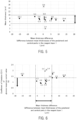
- FIG. 5 shows the relationship between the mean thickness and the difference between mean thicknesses of the peripheral and central parts (mean thickness difference) in the obtained reagent layer
- FIG. 6 shows the relationship between the CV (%) of glucose response current value (the reproducibility of glucose response current value) and the difference between mean thicknesses of the peripheral and central parts.
- the values shown in the graphs of FIGS. 5 and 6 are differences between the mean thicknesses of the peripheral and central parts (mean thickness difference) in the respective reagent layers.
- FIG. 5 data of mean thicknesses of the reagent layer in a range of 5 ⁇ m to 10 ⁇ m are plotted by marks of "black circle”, and data outside the range of 5 ⁇ m to 10 ⁇ m are plotted by marks of "x".
- FIG. 6 in data showing the difference between the mean thickness of the central and peripheral parts falling in a range of-6 ⁇ m to +5 ⁇ m, data of the Glu value reproducibility (%) of less than 1.4% are plotted by marks of "black circle”, and data of 1.4% or more are plotted by marks of "x”.
- the mean thickness of the reagent layer (height of reagent) was 5 ⁇ m to 10 ⁇ m, and when the difference between mean thicknesses of the peripheral and central parts (height difference) was -6 ⁇ m to +5 ⁇ m, CV(%) was less than 1.4%, lot to lot differences and within lot differences were reduced, and a high reproducibility was obtained.
Landscapes
- Life Sciences & Earth Sciences (AREA)
- Health & Medical Sciences (AREA)
- Chemical & Material Sciences (AREA)
- Physics & Mathematics (AREA)
- Biochemistry (AREA)
- Hematology (AREA)
- Chemical Kinetics & Catalysis (AREA)
- Electrochemistry (AREA)
- Biophysics (AREA)
- Analytical Chemistry (AREA)
- Molecular Biology (AREA)
- General Health & Medical Sciences (AREA)
- General Physics & Mathematics (AREA)
- Immunology (AREA)
- Pathology (AREA)
- Investigating Or Analysing Biological Materials (AREA)
- Apparatus Associated With Microorganisms And Enzymes (AREA)
Applications Claiming Priority (2)
| Application Number | Priority Date | Filing Date | Title |
|---|---|---|---|
| JP2022070369 | 2022-04-21 | ||
| JP2023064394A JP2023160758A (ja) | 2022-04-21 | 2023-04-11 | バイオセンサ |
Publications (1)
| Publication Number | Publication Date |
|---|---|
| EP4266038A1 true EP4266038A1 (fr) | 2023-10-25 |
Family
ID=86142794
Family Applications (1)
| Application Number | Title | Priority Date | Filing Date |
|---|---|---|---|
| EP23169187.4A Pending EP4266038A1 (fr) | 2022-04-21 | 2023-04-21 | Biocapteur |
Country Status (2)
| Country | Link |
|---|---|
| US (1) | US12590920B2 (fr) |
| EP (1) | EP4266038A1 (fr) |
Citations (15)
| Publication number | Priority date | Publication date | Assignee | Title |
|---|---|---|---|---|
| JPH063317A (ja) | 1992-06-18 | 1994-01-11 | Sumitomo Metal Ind Ltd | 酵素電極の製造方法 |
| WO2005043146A1 (fr) | 2003-10-30 | 2005-05-12 | Arkray, Inc. | Biocapteur et procede de fabrication associe |
| US20070278097A1 (en) * | 2003-06-20 | 2007-12-06 | Bhullar Raghbir S | Biosensor with laser-sealed capillary space and method of making |
| US20090178936A1 (en) * | 2007-12-10 | 2009-07-16 | Bayer Healthcare Llc | Porous Particle Reagent Compositions, Devices, and Methods for Biosensors |
| JP2011099693A (ja) | 2009-11-04 | 2011-05-19 | Nipro Corp | バイオセンサの製造方法 |
| US20120122197A1 (en) * | 2010-11-12 | 2012-05-17 | Abner David Jospeh | Inkjet reagent deposition for biosensor manufacturing |
| US20120150005A1 (en) * | 2010-12-09 | 2012-06-14 | Abbott Diabetes Care Inc. | Analyte Sensors with a Sensing Surface Having Small Sensing Spots |
| EP2554982A1 (fr) * | 2010-03-31 | 2013-02-06 | Cci Corporation | Biocapteur |
| JP2013083634A (ja) | 2011-09-26 | 2013-05-09 | Arkray Inc | グルコースセンサ |
| US20140373347A1 (en) * | 2012-03-15 | 2014-12-25 | Murata Manufacturing Co., Ltd. | Method for manufacturing biosensor |
| US20150201491A1 (en) * | 2012-09-26 | 2015-07-16 | Fujifilm Corporation | Pattern forming method, electronic wiring substrate, optical device, and pattern forming apparatus |
| JP2017520773A (ja) | 2014-07-17 | 2017-07-27 | ライフスキャン・スコットランド・リミテッド | ナフトキノン系メディエーター及びfad−gdhを含有した酵素試薬層を有する、電気化学式分析検査ストリップ |
| US9829459B2 (en) * | 2007-12-10 | 2017-11-28 | Ascensia Diabetes Care Holdings Ag | Electrochemical test sensor and method of forming the same |
| JP2018013400A (ja) | 2016-07-20 | 2018-01-25 | アークレイ株式会社 | アスコルビン酸応答電極およびバイオセンサ |
| EP4000517A1 (fr) * | 2020-11-23 | 2022-05-25 | Roche Diabetes Care GmbH | Électrode de travail pour un capteur d'analyte |
Family Cites Families (1)
| Publication number | Priority date | Publication date | Assignee | Title |
|---|---|---|---|---|
| JP6773507B2 (ja) * | 2016-09-30 | 2020-10-21 | アークレイ株式会社 | バイオセンサ、その製造方法、グルコース又はラクテートの濃度測定方法及び濃度測定システム |
-
2023
- 2023-04-20 US US18/137,102 patent/US12590920B2/en active Active
- 2023-04-21 EP EP23169187.4A patent/EP4266038A1/fr active Pending
Patent Citations (15)
| Publication number | Priority date | Publication date | Assignee | Title |
|---|---|---|---|---|
| JPH063317A (ja) | 1992-06-18 | 1994-01-11 | Sumitomo Metal Ind Ltd | 酵素電極の製造方法 |
| US20070278097A1 (en) * | 2003-06-20 | 2007-12-06 | Bhullar Raghbir S | Biosensor with laser-sealed capillary space and method of making |
| WO2005043146A1 (fr) | 2003-10-30 | 2005-05-12 | Arkray, Inc. | Biocapteur et procede de fabrication associe |
| US9829459B2 (en) * | 2007-12-10 | 2017-11-28 | Ascensia Diabetes Care Holdings Ag | Electrochemical test sensor and method of forming the same |
| US20090178936A1 (en) * | 2007-12-10 | 2009-07-16 | Bayer Healthcare Llc | Porous Particle Reagent Compositions, Devices, and Methods for Biosensors |
| JP2011099693A (ja) | 2009-11-04 | 2011-05-19 | Nipro Corp | バイオセンサの製造方法 |
| EP2554982A1 (fr) * | 2010-03-31 | 2013-02-06 | Cci Corporation | Biocapteur |
| US20120122197A1 (en) * | 2010-11-12 | 2012-05-17 | Abner David Jospeh | Inkjet reagent deposition for biosensor manufacturing |
| US20120150005A1 (en) * | 2010-12-09 | 2012-06-14 | Abbott Diabetes Care Inc. | Analyte Sensors with a Sensing Surface Having Small Sensing Spots |
| JP2013083634A (ja) | 2011-09-26 | 2013-05-09 | Arkray Inc | グルコースセンサ |
| US20140373347A1 (en) * | 2012-03-15 | 2014-12-25 | Murata Manufacturing Co., Ltd. | Method for manufacturing biosensor |
| US20150201491A1 (en) * | 2012-09-26 | 2015-07-16 | Fujifilm Corporation | Pattern forming method, electronic wiring substrate, optical device, and pattern forming apparatus |
| JP2017520773A (ja) | 2014-07-17 | 2017-07-27 | ライフスキャン・スコットランド・リミテッド | ナフトキノン系メディエーター及びfad−gdhを含有した酵素試薬層を有する、電気化学式分析検査ストリップ |
| JP2018013400A (ja) | 2016-07-20 | 2018-01-25 | アークレイ株式会社 | アスコルビン酸応答電極およびバイオセンサ |
| EP4000517A1 (fr) * | 2020-11-23 | 2022-05-25 | Roche Diabetes Care GmbH | Électrode de travail pour un capteur d'analyte |
Also Published As
| Publication number | Publication date |
|---|---|
| US20230341347A1 (en) | 2023-10-26 |
| US12590920B2 (en) | 2026-03-31 |
Similar Documents
| Publication | Publication Date | Title |
|---|---|---|
| CN100487442C (zh) | 薄型分析用具 | |
| US9976168B2 (en) | Substance measurement method and measurement device employing electrochemical biosensor | |
| RU2490622C2 (ru) | Тестовые датчики, способы и системы с множеством зон и потенциалов | |
| US6325917B1 (en) | Method and apparatus for automatic analysis | |
| US8500990B2 (en) | Electrochemical biosensors based on NAD(P)-dependent dehydrogenase enzymes | |
| US9753004B2 (en) | Electrochemical biosensor with improved accuracy | |
| US10203298B2 (en) | Electrochemical cell and method of making an electrochemical cell | |
| US6447657B1 (en) | Biosensor | |
| CN104407124A (zh) | 作为用于生物传感器的对照溶液的内部参考的可氧化的物质 | |
| US10451577B2 (en) | Substance measuring method and measuring apparatus using electrochemical biosensor | |
| JP6448627B2 (ja) | 裸電極に相対する可溶性電気化学的活性コーティングを備える電気化学式分析試験ストリップ | |
| EP3885761A1 (fr) | Biodétecteur et procédé de mesure l'utilisant | |
| EP4266037A1 (fr) | Biocapteur et procédé de fabrication de biocapteur | |
| EP4266038A1 (fr) | Biocapteur | |
| US7648624B2 (en) | Oxygen sensor | |
| CN109946352A (zh) | 用于电势型生物传感器的反应试剂及其应用 | |
| JP2023160758A (ja) | バイオセンサ | |
| US20210255134A1 (en) | Biosensor and method for producing same | |
| US20250127428A1 (en) | Biosensor | |
| JP2023160759A (ja) | バイオセンサ及びバイオセンサの製造方法 | |
| CN116930284A (zh) | 生物传感器 | |
| CN116930285A (zh) | 生物传感器和生物传感器的制造方法 | |
| JP2021156877A (ja) | バイオセンサおよびそれを用いた測定方法 | |
| US20150027905A1 (en) | Reagent composition for biosensors and biosensor comprising reagent layer formed of the same | |
| JP4635258B2 (ja) | バイオセンサー |
Legal Events
| Date | Code | Title | Description |
|---|---|---|---|
| STAA | Information on the status of an ep patent application or granted ep patent |
Free format text: STATUS: THE APPLICATION HAS BEEN PUBLISHED |
|
| PUAI | Public reference made under article 153(3) epc to a published international application that has entered the european phase |
Free format text: ORIGINAL CODE: 0009012 |
|
| AK | Designated contracting states |
Kind code of ref document: A1 Designated state(s): AL AT BE BG CH CY CZ DE DK EE ES FI FR GB GR HR HU IE IS IT LI LT LU LV MC ME MK MT NL NO PL PT RO RS SE SI SK SM TR |
|
| STAA | Information on the status of an ep patent application or granted ep patent |
Free format text: STATUS: REQUEST FOR EXAMINATION WAS MADE |
|
| 17P | Request for examination filed |
Effective date: 20240424 |
|
| RBV | Designated contracting states (corrected) |
Designated state(s): AL AT BE BG CH CY CZ DE DK EE ES FI FR GB GR HR HU IE IS IT LI LT LU LV MC ME MK MT NL NO PL PT RO RS SE SI SK SM TR |
|
| STAA | Information on the status of an ep patent application or granted ep patent |
Free format text: STATUS: EXAMINATION IS IN PROGRESS |
|
| 17Q | First examination report despatched |
Effective date: 20250730 |