EP4266274A1 - Dispositif de transport pour le transport de pièces de monnaie - Google Patents
Dispositif de transport pour le transport de pièces de monnaie Download PDFInfo
- Publication number
- EP4266274A1 EP4266274A1 EP23168716.1A EP23168716A EP4266274A1 EP 4266274 A1 EP4266274 A1 EP 4266274A1 EP 23168716 A EP23168716 A EP 23168716A EP 4266274 A1 EP4266274 A1 EP 4266274A1
- Authority
- EP
- European Patent Office
- Prior art keywords
- coins
- coin
- section
- chain link
- conveyor
- Prior art date
- Legal status (The legal status is an assumption and is not a legal conclusion. Google has not performed a legal analysis and makes no representation as to the accuracy of the status listed.)
- Pending
Links
Images


Classifications
-
- G—PHYSICS
- G07—CHECKING-DEVICES
- G07D—HANDLING OF COINS OR VALUABLE PAPERS, e.g. TESTING, SORTING BY DENOMINATIONS, COUNTING, DISPENSING, CHANGING OR DEPOSITING
- G07D1/00—Coin dispensers
-
- G—PHYSICS
- G07—CHECKING-DEVICES
- G07D—HANDLING OF COINS OR VALUABLE PAPERS, e.g. TESTING, SORTING BY DENOMINATIONS, COUNTING, DISPENSING, CHANGING OR DEPOSITING
- G07D3/00—Sorting a mixed bulk of coins into denominations
-
- B—PERFORMING OPERATIONS; TRANSPORTING
- B65—CONVEYING; PACKING; STORING; HANDLING THIN OR FILAMENTARY MATERIAL
- B65G—TRANSPORT OR STORAGE DEVICES, e.g. CONVEYORS FOR LOADING OR TIPPING, SHOP CONVEYOR SYSTEMS OR PNEUMATIC TUBE CONVEYORS
- B65G17/00—Conveyors having an endless traction element, e.g. a chain, transmitting movement to a continuous or substantially-continuous load-carrying surface or to a series of individual load-carriers; Endless-chain conveyors in which the chains form the load-carrying surface
- B65G17/06—Conveyors having an endless traction element, e.g. a chain, transmitting movement to a continuous or substantially-continuous load-carrying surface or to a series of individual load-carriers; Endless-chain conveyors in which the chains form the load-carrying surface having a load-carrying surface formed by a series of interconnected, e.g. longitudinal, links, plates, or platforms
- B65G17/08—Conveyors having an endless traction element, e.g. a chain, transmitting movement to a continuous or substantially-continuous load-carrying surface or to a series of individual load-carriers; Endless-chain conveyors in which the chains form the load-carrying surface having a load-carrying surface formed by a series of interconnected, e.g. longitudinal, links, plates, or platforms the surface being formed by the traction element
-
- B—PERFORMING OPERATIONS; TRANSPORTING
- B65—CONVEYING; PACKING; STORING; HANDLING THIN OR FILAMENTARY MATERIAL
- B65G—TRANSPORT OR STORAGE DEVICES, e.g. CONVEYORS FOR LOADING OR TIPPING, SHOP CONVEYOR SYSTEMS OR PNEUMATIC TUBE CONVEYORS
- B65G17/00—Conveyors having an endless traction element, e.g. a chain, transmitting movement to a continuous or substantially-continuous load-carrying surface or to a series of individual load-carriers; Endless-chain conveyors in which the chains form the load-carrying surface
- B65G17/30—Details; Auxiliary devices
- B65G17/32—Individual load-carriers
-
- B—PERFORMING OPERATIONS; TRANSPORTING
- B65—CONVEYING; PACKING; STORING; HANDLING THIN OR FILAMENTARY MATERIAL
- B65G—TRANSPORT OR STORAGE DEVICES, e.g. CONVEYORS FOR LOADING OR TIPPING, SHOP CONVEYOR SYSTEMS OR PNEUMATIC TUBE CONVEYORS
- B65G17/00—Conveyors having an endless traction element, e.g. a chain, transmitting movement to a continuous or substantially-continuous load-carrying surface or to a series of individual load-carriers; Endless-chain conveyors in which the chains form the load-carrying surface
- B65G17/30—Details; Auxiliary devices
- B65G17/46—Means for holding or retaining the loads in fixed position on the load-carriers, e.g. magnetic
Definitions
- the invention relates to a conveyor device for conveying coins from a first level to a second higher level, comprising a coin inlet at the first level and a coin outlet at the second level, and comprising a drive-driven endless conveyor for conveying coins from the coin inlet the coin outlet, whereby the endless conveyor is a chain link conveyor with a plurality of chain links connected in an articulated manner.
- Such conveying devices With such conveying devices, coins can be conveyed from a lower level to a higher level. This may be necessary, for example, in payment machines or money changing machines or even in slot machines.
- such conveying devices have a coin inlet at the lower level, via which the coins to be conveyed are fed to the conveying device, in particular an endless chain link conveyor.
- the coins are carried by chain links of the endless chain link conveyor and brought to the higher level, where they usually fall from the chain links due to gravity into a coin outlet. For example, the coins can be paid out via the coin outlet.
- chain link conveyors With chain link conveyors, the coins are usually held mechanically on the chain links during conveying, in contrast to conveyor belts where coins are held by static friction.
- chain link conveyors offer reliable conveyance of coins.
- Such a conveyor device is known WO 2018/141421 A1 .
- the conveyor chain of this conveyor device is guided in a modular rail system consisting of a plurality of rail elements that are detachably connected to one another. This makes it easy to realize different routes for the conveyor chain, in particular different heights of the conveyor path.
- the chain links of the known chain conveyor have driving devices in the form of driving projections for carrying coins in the course of their conveyance a lower level to a higher level. In order to prevent coins carried by the carrying devices from falling, the oval formed by the chain conveyor is inclined relative to the vertical.
- a pressure element for pressing the coins transported by the conveyor loop onto the conveyor loop is proposed.
- the pressure element extends essentially along the ascending section of the conveyor loop.
- Such a pressure element reliably prevents coins from falling even when the conveyor loop rises vertically, so that a smaller size of the conveyor device is possible, especially when there is a large difference in height between the first and second levels.
- the construction with the pressure element is complex and, in particular, a pressure element that is fixed relative to the conveyor chain entails significant wear and a risk of maintenance failures.
- a pressure element that moves with the conveyor loop or parallel to the conveyor loop increases the design effort considerably.
- the invention is therefore based on the object of providing a conveyor device of the type mentioned at the outset, with which a small size is made possible in a structurally simple and low-maintenance manner, even with large height differences between the first and second levels.
- the invention solves the problem in that the chain links each have at least one coin holding web, which holds coins to be conveyed, on the one hand, against a conveying direction of the coins from the first level to the second level and, on the other hand, transversely to the conveying direction on the respective chain link holds.
- coins are conveyed from a first, lower level to a second, higher level.
- the coins to be mined are preferably payment coins of a specific currency, for example Euro coins, or the like. But it can also be other valuable coins or tokens.
- the coins to be mined are preferably made of a metal. However, other materials are also conceivable, for example plastic.
- the coins to be conveyed are fed to the endless chain link conveyor according to the invention via a coin inlet at the first, lower level.
- the endless chain link conveyor consists of a large number of articulated chain links and is driven in rotation by a drive during operation. As a result, coins supplied via the coin inlet are conveyed from the first level to the second level.
- a coin outlet is provided on the higher second level, through which the coins conveyed to the second level are issued for further use, for example paid out.
- the conveying device can also include a coin hopper which is connected to the coin inlet and feeds coins to it for conveyance to the second level, for example for payout.
- the chain links according to the invention take coins fed in via the coin inlet and hold them mechanically to the second level during conveyance.
- the joints temporarily pivot with one another connected chain links.
- On the second level for example due to gravity, the coins can fall into the coin outlet from the chain links that change their orientation during rotation.
- An electric drive motor can be provided to drive the chain link conveyor.
- the drive can rotate a gear that meshes with corresponding teeth of the chain links and thus rotates the chain link conveyor.
- the chain link conveyor can have a housing in which the chain links are rotatably arranged.
- the chain links of the chain link conveyor each have at least one coin holding web.
- the chain links can also each have more than one coin holding bar, for example two coin holding bars.
- the at least one coin holding web holds the coins to be conveyed in the course of conveying from the first level to the second level, on the one hand, against the conveying direction of the coins.
- the at least one coin holding web prevents coins from falling downwards against the conveying direction during conveyance to the second level.
- the at least one coin holding bar holds the Coins to be conveyed during conveyance from the first level to the second level also transversely to the conveying direction on the respective chain link, in particular perpendicular to the conveying direction.
- the at least one coin holding web also holds the coins against the coins falling sideways or tipping off the chain link, as would be possible in particular with a steep rise angle up to a vertical rise of the chain link conveyor without providing a pressure element.
- the coins are therefore held in a direction away from the respective chain link or a base body of the respective chain link.
- the at least one coin holding web forms a pocket in which the coins to be conveyed are at least partially received during conveyance to the second level. In this way, the coins are reliably held mechanically by the chain links alone, even without the provision of an additional pressure element and even at steep angles of rise of the chain link conveyor up to a vertical rise of the chain link conveyor, and are thus secured against undesirable premature falling due to gravity.
- the invention is based on the surprising finding that even with the at least one coin holding bar, safe separation and conveying of coins is possible, especially if the amount of coins to be conveyed is designed or selected accordingly.
- euro coins differ sufficiently little from each other in their thickness and diameter so that they can be separated safely.
- a selection of coins permitted for the conveyor device can be made, for example coins with a very different diameter or a very different thickness are not allowed and can be rejected and returned accordingly when inserted.
- the at least one coin holding bar can be designed in such a way that it always holds exactly one coin during conveyance from the first level to the second level.
- the at least one coin holding web can therefore be designed in such a way that two coins cannot be held by it at the same time, in particular not lying on top of one another. If this is desired, it is also possible to design the coin holding bar in such a way that it can simultaneously hold several coins during conveyance from the first level to the second level, especially if particularly large conveying capacities are desired.
- the chain link conveyor has a first section that rises in the driven state and a second section that descends in the driven state, the first section at its higher end merging into the higher end of the second section via a third section, and where the second section at its lower end merges into the lower end of the first section via a fourth section.
- a third section of the chain link conveyor is thus provided between the higher end of the first section and the second section and a fourth section of the chain link conveyor is provided between the lower end of the second section and the first section.
- the sections are formed by the interconnected chain links of the chain link conveyor. Together, the sections form the conveying section of the chain link conveyor. For example, you can form an oval conveyor line.
- the first and second sections can, for example, be arranged parallel to one another.
- the first section can rise in the vertical direction.
- the second section can descend in a vertical direction.
- a vertical rise and/or a vertical descent of the Chain link conveyor enables a particularly compact design of the conveyor device even with a large height difference between the first and second levels.
- the design of the chain links according to the invention ensures that the coins being conveyed are held securely at all times, particularly in the first section.
- the third section can be curved, preferably curved in a semicircle.
- the fourth section can be curved, preferably curved in a semicircle.
- a symmetrical course of the chain link conveyor is possible, for example as an oval.
- the coins to be conveyed can fall from the chain links due to gravity, particularly in the area of the third section, due to the alignment of the chain links changing in the course of the curvature of the third section and reach the coin outlet.
- the time or place at which the coins fall can be adjusted as desired by specifically designing the curvature of the third section.
- the third section can also have a shape that deviates from a semicircle, especially if an earlier drop of the coins is desired.
- the third section it is possible for the third section to have a first curved subsection adjoining the first section with a first, relatively small radius of curvature and a second subsection adjoining the first curved subsection and opening into the second section of the chain link conveyor.
- the second subsection serves to bridge between the more curved first subsection and the second section of the chain link conveyor.
- the second subsection can be straight or also have a curvature, in particular with a second radius of curvature that is larger than the first radius of curvature of the first curvature section.
- the drive can be arranged within the chain link conveyor, with a gear driven by the drive meshing with the chain links in the area of the second section.
- the drive can, for example, comprise an electric motor. Arranging the drive within the chain link conveyor and in the area of the second section, preferably at a lower end of the chain link conveyor, allows a particularly compact design of the conveyor device according to the invention.
- the at least one coin holding web can form an undercut through which the coins to be conveyed are held.
- the at least one coin holding web can be L-shaped in cross section. Together with, for example, a cuboid base body of the chain link, the coin holding web can, for example, form a C-shape in cross section. This creates a pocket in which the coins to be conveyed are held particularly securely, even transversely to the conveying direction, from the first level to the second level.
- the undercut it is possible that several coins can be placed one on top of the other in the pocket formed by the undercut, or that only exactly one coin can be received in the pocket formed by the undercut.
- the chain links can each have two coin holding webs that run at an angle to one another.
- the coin holding bars can be designed as explained in this application for the at least one coin holding bar.
- two coin holding bars would also be conceivable, for example, each of which has a non-straight course, for example a curved course.
- the two coin holding bars can further be arranged along a V-shape and designed to support coins when conveying them from the first level to the to hold the second level in a receptacle formed by the V-shape.
- the opening of the V-shape is directed in the conveying direction in the first section of the chain link conveyor. The coins are therefore held securely in the V-shaped holder during conveyance from the first level to the second level.
- the two coin holding bars of a chain link do not touch each other.
- the two coin holding bars do not have to form a closed V.
- the aforementioned configuration can advantageously enable, for example, smaller interfering elements or dirt to fall out downwards, so that they are not conveyed up to the coin outlet.
- a section can also be formed between the ends of the coin holding webs with which a gear of the drive for driving the chain link conveyor meshes.
- the chain links can each be designed in one piece with the at least one coin holding bar.
- the chain links can be made of plastic.
- the chain links can each be manufactured using a plastic injection molding process. This enables particularly simple production and later assembly and disassembly.
- the chain links can be connected to one another in an articulated manner via a snap connection, in particular releasably.
- a snap connection in particular releasably.
- This enables particularly simple assembly and disassembly and thus particularly easy adaptability of the chain link conveyor to different conveying heights.
- one or more locking receptacles can be provided at one end of each chain link and one or more locking projections can be provided at an opposite end of the chain link.
- the locking projections can, for example, be cylindrical in cross section.
- the snap-in recordings can be made accordingly Cross section be C-shaped.
- the locking projections and locking receptacles can also be designed in one piece with the respective chain link.
- the coin inlet can have a floor chute for coins supplied via the coin inlet.
- coins can be fed to the coin inlet from a hopper, for example.
- the coins fall through the coin inlet onto the chain link conveyor, especially in the area of the fourth section.
- the coins fall directly onto chain links of the chain link conveyor and, under certain circumstances, coins standing on their side edges can roll or an undesirable accumulation of coins can occur, which can make it difficult to convey the coins, especially separating them.
- the floor slide avoids these problems.
- the floor slide prevents the coins from falling directly onto the chain links.
- the floor chute is arranged in such a way that coins fed in via the coin inlet first fall onto the floor chute.
- the floor slide can be vibrated by the chain links of the chain link conveyor, which preferably move under the floor slide.
- the floor slide prevents coins from rolling or the accumulation of several coins in a particularly safe manner. At the same time, coins that would lie flat on the chain links are oriented for removal by a chain link.
- the floor slide is in particular designed to be stationary, so that the chain links move under the floor slide, particularly in the fourth section of the chain link conveyor.
- the floor chute may have a curved portion that conforms to a curvature of the fourth portion of the chain link conveyor.
- the floor slide can, for example, be designed as a sheet metal, in particular as a curved sheet metal, adapted to the curvature of the fourth section of the chain link conveyor. But a floor slide made of plastic or something similar would also be conceivable.
- an end of the floor slide opening onto the chain link conveyor can be designed non-perpendicular to the conveying direction of the chain link conveyor, preferably obliquely to the conveying direction or along a non-straight line.
- the end of the floor slide that opens onto the chain link conveyor can have a V-shaped cutout or another shape that deviates from a shape perpendicular to the conveying direction.
- coins rolling on their side edges are tipped so that they can subsequently be properly conveyed by the conveyor device. This also prevents unwanted coin accumulations even more reliably.
- the coin outlet can have a guide chute for conveying coins from the chain link conveyor, in particular for guiding coins falling from the chain links into the coin outlet. This can improve the feeding of coins from the chain link conveyor into the coin outlet.
- the chain links can also each have at least one lateral limiting web, preferably two lateral limiting webs arranged on opposite sides of a base body of the chain links, for laterally holding a coin to be conveyed. This also ensures that the coins are held sideways on the chain links at all times.
- the at least one lateral boundary web can also be formed in one piece with the chain link.
- the chain links each have two lateral limiting webs arranged opposite one another, which are spaced apart in such a way that the two smallest coins of the coins to be conveyed cannot be held next to one another between the limiting webs.
- the at least one coin holding bar can be dimensioned such that the two thinnest coins are too Coins to be conveyed cannot be held on top of each other by the at least one coin holding bar.
- the aforementioned configurations ensure that the coins are separated securely, for example for a targeted payout. Nevertheless, a high conveying speed is possible with the conveying device according to the invention, for example up to five coins per second.
- the chain link conveyor according to the invention can have a modular structure. This makes it easy to adapt to different heights. For example, adjustments to the conveyor device according to the invention are possible in the range of 300 mm to 2,000 mm.
- the coin outlet can comprise at least one sensor, designed to count and/or detect coins issued through the coin outlet.
- the conveying device according to the invention can be used, for example, in vending machine systems both as an input and as an output device for coins.
- a circuit board with electronics can be attached to the coin outlet of the conveyor device, for example with a Sensors and, if necessary, evaluation electronics are equipped.
- the chain link conveyor is designed in such a way that it feeds coins individually to the coin outlet, the coins can be counted by providing a suitable sensor.
- the sensor can, for example, comprise an optical measuring device, for example a light barrier. But it can also be a capacitive or inductive sensor.
- the results of the coin counting can preferably be transmitted via a digital interface to control the vending machine system.
- An inductive sensor for example, can also be used as a sensor, which can distinguish the coins discharged through the coin outlet based on their diameter, for example. In this way, it is possible to easily identify the respective coin type or coin value. On this basis, for example, specific amounts of money can be paid out or counted, or a certain number of coins can be checked for complete payout.
- a payout speed could also be achieved by controlling the speed of the chain link conveyor, in particular its drive.
- Illustrated conveyor device for conveying coins from a first level to a second, higher level.
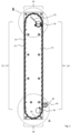
- the conveying device comprises a coin inlet 10, via which coins to be conveyed are fed to an endless chain link conveyor 12 arranged in a housing 11 shown partially open.
- the chain link conveyor 12 has a large number of chain links 14 which are connected to one another in an articulated manner, which in the example shown are connected to one another in an articulated manner via a locking connection, as will be explained in more detail below.
- the coin inlet 10 is located at the first lower level.
- a coin outlet 16 is provided, to which coins conveyed from the first level to the second level are fed by the chain link conveyor 12.
- the coins can be fed to the coin inlet 10, for example via a coin hopper. From that Coin outlet 16 allows the coins to be used for further purposes, for example to be paid out.
- a drive 18, for example an electric motor 18, drives a gear 20 in rotation, which meshes with a corresponding toothing structure of the chain links 14 of the chain link conveyor 12, so that the chain links 14 of the chain link conveyor 12 are driven in rotation by the drive 18, in Figure 1 clockwise.
- Coins supplied via the coin inlet 10 are taken along by the chain links 14 in a manner to be explained in more detail below and conveyed from the first level to the second level, where they are fed to the coin outlet 16.
- the chain link conveyor 12 has a first section 22 which rises vertically in the driven state and a second section 24 which descends vertically in the driven state.
- the upper end of the first section 22 merges into the upper end of the second section 24 via a semicircularly curved third section 26.
- the lower end of the second section 24 merges into the lower end of the first section 22 via a fourth section 28 which is also curved in a semicircle.
- the chain link conveyor 12 forms an oval with parallel first and second sections 22, 24 and complementary third and fourth sections 26, 28.
- the drive 18 together with the gear 20 is arranged outside the chain link conveyor 12, in particular outside the housing 11, namely on one side of the chain link conveyor 12 in the lower region of the chain link conveyor 12.
- This can simplify the disassembly and assembly of the chain link conveyor 12.
- the drive 18 and the gear 20 could also be arranged within the chain link conveyor 12, for example mirrored to that in Figure 1 shown arrangement, so that the gear in the second section 24 meshes with tooth sections of the chain links 14. Due to the articulated locking connection of the chain links 14 to one another, the chain link conveyor 12 can be easily assembled or disassembled from the Chain links 14 can be adapted to different delivery heights between the first and second levels.
- a floor slide 30 is provided below the coin inlet 10 and is arranged above the chain links 14 rotating underneath it, in Figure 1 shown in dashed lines.
- the floor slide is shown in an enlarged view Figure 2 easier to recognize.
- the coins carried by the chain links 14 fall in the area of the second section 26 due to the changing orientation of the chain links 14 due to gravity into the coin outlet 16.
- the coins can thereby pass through a guide chute arranged along the line 32 be directed to the coin outlet 16.
- Figure 4 shows an alternative embodiment of the third section 26 'of the chain link conveyor 12.
- the third section 26' has a first subsection 34 with a smaller radius of curvature than the second section 26 according to the exemplary embodiment described above.
- the second section 26 'in the in Figure 4 shown embodiment has a second subsection 36, which opens into the second section 24 with a significantly larger radius of curvature than the first subsection 34.
- the chain link conveyor 14 comprises a cuboid base body 38 at one end of which locking receptacles 40 which are C-shaped in cross section are formed and at the opposite end of which cylindrical locking projections 42 are formed.
- any number of chain links 14 can be easily attached via the locking receptacles 40 or locking projections 42 Can be releasably connected to one another in a snap-locking manner.
- external guide pins 44 are also formed, with which the chain links 14 are guided in the course of their rotational movement.
- latching receptacles 40 and latching projections 42 would also be conceivable, so that the latching receptacles 40 are formed at the end with the guide pin 44 and the latching projections 42 at the opposite end.
- a mixed embodiment would also be conceivable, in which a locking receptacle 40 and a locking projection 42 are formed at each end.
- Two coin holding webs 46 arranged along a V shape extend on the top of the base body 38.
- the coin holding webs 46 are each L-shaped in cross section and form an undercut or a pocket for receiving a coin 48, as shown in Figure 6 is shown.
- the coin holding bars 46 do not touch each other. Accordingly, they extend only along part of a V-shape, the receptacle of the V-shape in the first section 22 of the chain link conveyor 12 being directed in the conveying direction, i.e. upwards.
- the height of the coin holding webs 46 or their undercut is in the Figures 5 and 6 illustrated embodiment such that exactly one coin of the coins to be conveyed can be accommodated in the pocket formed by the coin holding webs 46, i.e. not two coins on top of each other. Due to the design of the coin holding webs 46 with an undercut, the coin 48 received therein is held in the first section 22 against the conveying direction of the coin 48 from the first level to the second level, i.e. against falling downwards. On the other hand, the coin 48 is also held transversely to the conveying direction on the chain link 14, in particular in such a way that the coin 48 cannot fall away from the base body 38 of the chain link 14 even during vertical conveyance upwards in the first section 22.
- the chain link 14 also includes two at opposite lateral ends Base body 38 arranged side boundary webs 50, through which the coins 48 are also secured against falling laterally from the chain link 14. In addition, the distance between the limiting webs 50 is such that no two coins can be held next to each other by a chain link 14.
- the chain link 14 according to the Figures 5 and 6 It is therefore a chain link of a Singulator chain link conveyor.
- a further exemplary embodiment of a chain link 14 ' is shown, which is also shown in FIG Figure 1
- the conveying device shown can be used.
- it is a chain link 14' to form an escalator chain link conveyor.
- This chain link 14 ' largely corresponds to the chain link 14 from the Figures 5 and 6 and like parts are provided with the same reference numerals.
- the coin holding webs 46 'of the chain link 14' from the Figures 7 and 8th arranged parallel to each other and connected to one another by a connecting web 62.
- the coin holding webs 46 ' are also L-shaped in cross section and form an undercut, but with a greater height than in the exemplary embodiment according to the Figures 5 and 6 , so that several coins 48 stacked on top of each other can be accommodated at the same time in the pockets formed by the coin holding webs 46 ', as in Figure 8 shown.
- the geometry of the coin holding webs 46' with the connecting web 62 in particular the parallel arrangement of the coin holding webs 46' with the connecting web 62 running transversely to the coin holding webs 46', prevents coins held by the coin holding webs 46' from tipping too much.
- the depth of the pockets formed by the coin holding webs 46' can also be limited.
- the conveying capacity of the conveying device can be significantly increased by the coin holding webs 46 ', with the coins 48 naturally not being separated. Therefore, no side boundary bars are required.
- the Figures 7 and 8th Corresponding limiting webs can be provided, as well as possibly on the limiting webs 50 in the exemplary embodiment according to Figures 5 and 6 can be dispensed with.
- a projection 64 for example triangular in cross section, is also arranged on the underside of the connecting web 62. This prevents coins 48 from accumulating and possibly becoming trapped between adjacent chain links 14'.
- Such a projection 64 can also have a different cross-sectional shape and can also be used in the chain link 14 Figures 5 and 6 be provided.
- the chain links 14 and 14 ' are in particular formed in one piece and consist, for example, of a plastic. They can, for example, be manufactured using a plastic injection molding process.
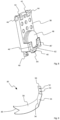
- the floor slide 30 of the conveyor device is shown in an enlarged perspective view.
- the floor slide 30 is designed as a sheet metal. Bores 52 are provided on a folded holding section 50, via which the floor slide 30 can be fastened, for example, to a part of the housing 11 of the conveyor device, for example by screwing.
- the holding section 50 merges into a flat base section 54, which in turn merges into a curved slide section 58 via a folding edge 56.
- the curved slide section 58 is adapted to the curved course of the fourth section 28 in such a way that the slide section 58 is located directly above the chain links 14 rotating underneath it during operation or rests on the chain links 14. In the latter case, the chain links 14 rotating through can advantageously cause the floor slide 30 to vibrate.
- the coin outlet 16 is assigned at least one sensor, designed to count and/or detect coins dispensed through the coin outlet 16. Associated evaluation electronics can also be provided accordingly.
Landscapes
- Physics & Mathematics (AREA)
- General Physics & Mathematics (AREA)
- Chain Conveyers (AREA)
Applications Claiming Priority (1)
| Application Number | Priority Date | Filing Date | Title |
|---|---|---|---|
| DE102022109634.3A DE102022109634A1 (de) | 2022-04-21 | 2022-04-21 | Fördervorrichtung zum Fördern von Münzen |
Publications (1)
| Publication Number | Publication Date |
|---|---|
| EP4266274A1 true EP4266274A1 (fr) | 2023-10-25 |
Family
ID=86096091
Family Applications (1)
| Application Number | Title | Priority Date | Filing Date |
|---|---|---|---|
| EP23168716.1A Pending EP4266274A1 (fr) | 2022-04-21 | 2023-04-19 | Dispositif de transport pour le transport de pièces de monnaie |
Country Status (2)
| Country | Link |
|---|---|
| EP (1) | EP4266274A1 (fr) |
| DE (1) | DE102022109634A1 (fr) |
Citations (6)
| Publication number | Priority date | Publication date | Assignee | Title |
|---|---|---|---|---|
| US5531331A (en) * | 1991-08-06 | 1996-07-02 | Barnett; Adam J. | Sorting of differently identified articles |
| DE102010025249A1 (de) * | 2010-06-26 | 2011-12-29 | Ermo Coin Tech Gmbh | Fördermodul in endlosbauweise |
| GB2513539A (en) * | 2013-02-04 | 2014-11-05 | Crane Payment Solutions Ltd | Conveying money items |
| US20170213408A1 (en) * | 2014-07-16 | 2017-07-27 | Crane Payment Solutions Limited | Conveying money items |
| WO2018115944A1 (fr) | 2016-12-23 | 2018-06-28 | Novomatic Ag | Élévateur à pièces de monnaie |
| WO2018141421A1 (fr) | 2017-02-03 | 2018-08-09 | Crane Payment Innovations Gmbh | Dispositif de transport de pièces de monnaie |
-
2022
- 2022-04-21 DE DE102022109634.3A patent/DE102022109634A1/de active Pending
-
2023
- 2023-04-19 EP EP23168716.1A patent/EP4266274A1/fr active Pending
Patent Citations (6)
| Publication number | Priority date | Publication date | Assignee | Title |
|---|---|---|---|---|
| US5531331A (en) * | 1991-08-06 | 1996-07-02 | Barnett; Adam J. | Sorting of differently identified articles |
| DE102010025249A1 (de) * | 2010-06-26 | 2011-12-29 | Ermo Coin Tech Gmbh | Fördermodul in endlosbauweise |
| GB2513539A (en) * | 2013-02-04 | 2014-11-05 | Crane Payment Solutions Ltd | Conveying money items |
| US20170213408A1 (en) * | 2014-07-16 | 2017-07-27 | Crane Payment Solutions Limited | Conveying money items |
| WO2018115944A1 (fr) | 2016-12-23 | 2018-06-28 | Novomatic Ag | Élévateur à pièces de monnaie |
| WO2018141421A1 (fr) | 2017-02-03 | 2018-08-09 | Crane Payment Innovations Gmbh | Dispositif de transport de pièces de monnaie |
Also Published As
| Publication number | Publication date |
|---|---|
| DE102022109634A1 (de) | 2023-10-26 |
Similar Documents
| Publication | Publication Date | Title |
|---|---|---|
| EP1694589B1 (fr) | Dispositif de separation pour pieces allongees et dispositif de transport desdites pieces | |
| DE2459251A1 (de) | Vorrichtung zur ausgabe einzelner muenzen | |
| DE2651664A1 (de) | Sortiermaschine | |
| DE69109956T2 (de) | Fördereinrichtung zum Vereinzeln von Münzen. | |
| DE10137843A1 (de) | Vorrichtung zum Sortieren und zum Weitertransport von Schüttgut | |
| EP2720202B1 (fr) | Dispositif de tri de monnaie | |
| DE3418489C2 (fr) | ||
| EP1450314B1 (fr) | Dispositif séparateur de pièces de monnaie | |
| EP4266274A1 (fr) | Dispositif de transport pour le transport de pièces de monnaie | |
| DE10317417B4 (de) | Vereinzelungs- und Fördervorrichtung | |
| AT391843B (de) | Vorrichtung zur einzelentnahme von gegenstaenden aus einem haufen und zur weiterfoerderung dieser gegenstaende | |
| EP0208190A1 (fr) | Réservoir pour des objets en forme de tige, notamment des cigarettes | |
| DE60028163T2 (de) | Vorrichtung zum Zuführen von Zigarren | |
| EP3559918B1 (fr) | Élévateur à pièces de monnaie | |
| EP1328170B1 (fr) | Contenant, dispositif et procede pour transporter des articles de forme allongee dans l'industrie du tabac | |
| DE1623178B2 (de) | Vorrichtung zum sortieren von muenzen und aehnlichen scheibenfoermigen gegenstaenden | |
| DE3833034A1 (de) | Foerdervorrichtung | |
| DE102023122584A1 (de) | Handhabungsvorrichtung, insbesondere Sortiervorrichtung, zu einem Handhaben von Produkten, Produktionsmaschine mit der Handhabungsvorrichtung sowie Verfahren zu einem Handhaben von Produkten mit der Handhabungsvorrichtung | |
| DE69924913T2 (de) | Vorrichtung zum Bilden von Stapeln von Gegenständen | |
| DE4332341A1 (de) | Vorrichtung zum Zusammenführen und Beschleunigen eines Stroms aufrecht stehender Flaschen o. dgl. | |
| DE202007001682U1 (de) | Leergutrücknahmeautomat | |
| WO2018141421A1 (fr) | Dispositif de transport de pièces de monnaie | |
| DE4310480A1 (de) | Gurtbecherförderer zum kontinuierlichen Steil- und Senkrechtfördern von Schüttgut | |
| DE20206895U1 (de) | Vorrichtung zum Verbreitern und Verlangsamen eines Stroms aufrechtstehender Flaschen | |
| AT526488A1 (de) | Transportwelle und Abgabevorrichtung |
Legal Events
| Date | Code | Title | Description |
|---|---|---|---|
| STAA | Information on the status of an ep patent application or granted ep patent |
Free format text: STATUS: THE APPLICATION HAS BEEN PUBLISHED |
|
| PUAI | Public reference made under article 153(3) epc to a published international application that has entered the european phase |
Free format text: ORIGINAL CODE: 0009012 |
|
| AK | Designated contracting states |
Kind code of ref document: A1 Designated state(s): AL AT BE BG CH CY CZ DE DK EE ES FI FR GB GR HR HU IE IS IT LI LT LU LV MC ME MK MT NL NO PL PT RO RS SE SI SK SM TR |
|
| STAA | Information on the status of an ep patent application or granted ep patent |
Free format text: STATUS: REQUEST FOR EXAMINATION WAS MADE |
|
| 17P | Request for examination filed |
Effective date: 20240418 |
|
| RBV | Designated contracting states (corrected) |
Designated state(s): AL AT BE BG CH CY CZ DE DK EE ES FI FR GB GR HR HU IE IS IT LI LT LU LV MC ME MK MT NL NO PL PT RO RS SE SI SK SM TR |
|
| STAA | Information on the status of an ep patent application or granted ep patent |
Free format text: STATUS: EXAMINATION IS IN PROGRESS |
|
| 17Q | First examination report despatched |
Effective date: 20250218 |
|
| RIC1 | Information provided on ipc code assigned before grant |
Ipc: G07D 9/00 20060101AFI20250819BHEP Ipc: B65G 17/08 20060101ALN20250819BHEP Ipc: B65G 17/32 20060101ALN20250819BHEP Ipc: B65G 17/46 20060101ALN20250819BHEP |
|
| GRAP | Despatch of communication of intention to grant a patent |
Free format text: ORIGINAL CODE: EPIDOSNIGR1 |
|
| STAA | Information on the status of an ep patent application or granted ep patent |
Free format text: STATUS: GRANT OF PATENT IS INTENDED |
|
| RIC1 | Information provided on ipc code assigned before grant |
Ipc: G07D 9/00 20060101AFI20250910BHEP Ipc: B65G 17/08 20060101ALN20250910BHEP Ipc: B65G 17/32 20060101ALN20250910BHEP Ipc: B65G 17/46 20060101ALN20250910BHEP |
|
| INTG | Intention to grant announced |
Effective date: 20250929 |
|
| GRAJ | Information related to disapproval of communication of intention to grant by the applicant or resumption of examination proceedings by the epo deleted |
Free format text: ORIGINAL CODE: EPIDOSDIGR1 |
|
| STAA | Information on the status of an ep patent application or granted ep patent |
Free format text: STATUS: EXAMINATION IS IN PROGRESS |
|
| GRAP | Despatch of communication of intention to grant a patent |
Free format text: ORIGINAL CODE: EPIDOSNIGR1 |
|
| STAA | Information on the status of an ep patent application or granted ep patent |
Free format text: STATUS: GRANT OF PATENT IS INTENDED |
|
| INTC | Intention to grant announced (deleted) | ||
| INTG | Intention to grant announced |
Effective date: 20260216 |
|
| RIC1 | Information provided on ipc code assigned before grant |
Ipc: G07D 9/00 20060101AFI20260209BHEP Ipc: B65G 17/08 20060101ALN20260209BHEP Ipc: B65G 17/32 20060101ALN20260209BHEP Ipc: B65G 17/46 20060101ALN20260209BHEP |
|
| GRAS | Grant fee paid |
Free format text: ORIGINAL CODE: EPIDOSNIGR3 |
|
| GRAA | (expected) grant |
Free format text: ORIGINAL CODE: 0009210 |
|
| STAA | Information on the status of an ep patent application or granted ep patent |
Free format text: STATUS: THE PATENT HAS BEEN GRANTED |