EP4266345A1 - X-ray tube - Google Patents
X-ray tube Download PDFInfo
- Publication number
- EP4266345A1 EP4266345A1 EP21909753.2A EP21909753A EP4266345A1 EP 4266345 A1 EP4266345 A1 EP 4266345A1 EP 21909753 A EP21909753 A EP 21909753A EP 4266345 A1 EP4266345 A1 EP 4266345A1
- Authority
- EP
- European Patent Office
- Prior art keywords
- voltage cable
- power feed
- feed section
- anode target
- vacuum enclosure
- Prior art date
- Legal status (The legal status is an assumption and is not a legal conclusion. Google has not performed a legal analysis and makes no representation as to the accuracy of the status listed.)
- Pending
Links
Images

Classifications
-
- H—ELECTRICITY
- H01—ELECTRIC ELEMENTS
- H01J—ELECTRIC DISCHARGE TUBES OR DISCHARGE LAMPS
- H01J35/00—X-ray tubes
- H01J35/02—Details
- H01J35/16—Vessels; Containers; Shields associated therewith
- H01J35/165—Vessels; Containers; Shields associated therewith joining connectors to the tube
-
- H—ELECTRICITY
- H05—ELECTRIC TECHNIQUES NOT OTHERWISE PROVIDED FOR
- H05G—X-RAY TECHNIQUE
- H05G1/00—X-ray apparatus involving X-ray tubes; Circuits therefor
- H05G1/08—Electrical details
- H05G1/10—Power supply arrangements for feeding the X-ray tube
-
- H—ELECTRICITY
- H01—ELECTRIC ELEMENTS
- H01J—ELECTRIC DISCHARGE TUBES OR DISCHARGE LAMPS
- H01J35/00—X-ray tubes
- H01J35/02—Details
- H01J35/04—Electrodes ; Mutual position thereof; Constructional adaptations therefor
- H01J35/08—Anodes; Anti cathodes
-
- H—ELECTRICITY
- H01—ELECTRIC ELEMENTS
- H01J—ELECTRIC DISCHARGE TUBES OR DISCHARGE LAMPS
- H01J2235/00—X-ray tubes
- H01J2235/02—Electrical arrangements
-
- H—ELECTRICITY
- H01—ELECTRIC ELEMENTS
- H01J—ELECTRIC DISCHARGE TUBES OR DISCHARGE LAMPS
- H01J2235/00—X-ray tubes
- H01J2235/02—Electrical arrangements
- H01J2235/023—Connecting of signals or tensions to or through the vessel
- H01J2235/0233—High tension
-
- H—ELECTRICITY
- H01—ELECTRIC ELEMENTS
- H01J—ELECTRIC DISCHARGE TUBES OR DISCHARGE LAMPS
- H01J2235/00—X-ray tubes
- H01J2235/12—Cooling
- H01J2235/1216—Cooling of the vessel
Definitions
- Embodiments described herein relate generally to an X-ray tube.
- the fixed anode X-ray tubes comprise a vacuum enclosure, an anode target, a cathode filament, a power feed section, a high-voltage cable connected to the power feed section, and an insulating section which covers the power feed section and the high-voltage cable with insulating material.
- a flat portion at one end of the vacuum enclosure has an output window that transmits X-rays.
- the anode target is located inside the vacuum enclosure so as to oppose the output window.
- the cathode filament is located inside the vacuum enclosure and emits electrons to be irradiated onto the anode target.
- the high-voltage cable that supplies high voltage to the anode target is connected, and the area around the power feed section and the high-voltage cable is covered by an insulating material.
- Patent Literature 1 US 6,440,192 B
- the embodiments have been achieved in consideration of the above-provided points, and an object thereof is to provide an X-ray tube that can prevent a decrease in voltage holding capability.
- an X-ray tube of one embodiment includes a vacuum enclosure in which an output window which transmits X-rays is formed, an anode target provided in the vacuum enclosure so as to oppose the output window, a cathode filament provided in the vacuum enclosure, that emits electrons to be irradiated onto the anode target, a power feed section to which a high voltage cable is connected to supply high voltage to the anode target, and an insulating portion that covers the power feed section and the high-voltage cable with an insulating material, and the power feed section includes a contact surface with which a distal end surface of the high-voltage cable is brought into contact, and an angle formed by the contact surface and the side surface of the high-voltage cable is an acute angle.
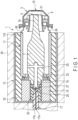
- the X-ray tube 1 of the first embodiment is a fixed anode type X-ray tube and comprises a vacuum enclosure 3, an anode target 5, a support 7, a cathode filament 9, an insulating enclosure 11, a tube container 13, a heat radiator 15, and a high voltage cable 17.
- the vacuum enclosure 3 maintains a vacuum inside and has a cylindrical shape with a distal end portion whose outer diameter gradually tapering down, which includes an output window 19 that transmits X-rays on a flat portion of a distal end surface thereof.
- the output window 19 is made of beryllium (Be), for example, as a material with low attenuation of X-rays.
- Be beryllium
- the anode target 5 is placed to oppose the output window 19, and the cathode filament 9 is placed on an outer circumferential side of the anode target 5. Note that a converging electrode 21 is provided between the anode target 5 and the cathode filament 9.
- a distal end portion 7a of the support 7 is located in a central portion of the vacuum enclosure 3, a distal end portion 7a of the support 7 is located.
- the distal end portion 7a of the support 7 is disposed on an inner circumferential side of the converging electrode 21 and supports the anode target 5 by the distal end.
- the other end portion 7b of the support 7 protrudes from the other end side of the insulating enclosure 11, and a joint member (an anode-side metal enclosure) 23 is brazed thereto.
- the insulating enclosure 11 and the support 7 jointed together in a sealed state by the joint member 23.
- a metal film 36 is formed on a distal end surface (one end surface) 11b of the insulating enclosure 11, and a cathode-side metal enclosure 24, which supports the cathode filament 9, is brazed to the metal film 36.
- an exhaust pipe 27 is provided to exhaust the inside of the vacuum enclosure 3 through an exhaust channel 25 formed inside the support 7, and further, a power feed section 29 is provided, to which the high voltage cable 17 is connected to apply high voltage to the anode target 5.
- the insulating heat radiator 15 has a female threaded portion, which is tightened to a male threaded portion formed on the other end portion 7b of the support 7, and one end surface thereof is brought into contact with the joint member 23.
- the heat radiator 15 is ceramics having high thermal conductivity characteristics of 20 W/m ⁇ K or higher and high voltage insulation of 10 kV/mm or higher, and when, for example, aluminum nitride is used, a high thermal conductivity of 90 W/m ⁇ K or higher can be achieved.
- the power feed section 29 includes a contact surface 29a with which the high voltage cable 17 is brought into contact, and the contact surface 29a is a flat surface.
- the high-voltage cable 17 is located on the inner circumferential side of the heat radiator 15 and is drawn out of the heat radiator 15.
- the high-voltage cable 17 is constituted by a core material 17a and a silicon resin-made coating material 17b that covers the core material 17a.
- a cable-side insulating material 32 is filled.
- the insulating enclosure 11, whose interior is vacuumed together with the vacuum enclosure 3, the other end portion 7b of the support 7, which protrudes from the insulating enclosure 11, a part of the heat radiator 15 and the like are accommodated in the tube container 13.
- the interior of the tube container 13 is filled with an insulating material 33 of the inner side of the tube.
- the tube inner-side insulating material 33 is filled between the tube container 13 and the insulating enclosure 11, the joint member 23 and the heat radiator 15.
- the cable side insulation material 32 and the tube inner-side insulation material 33 are, for example, potting materials such as of silicone resin.
- a cooling section 35 is arranged on the outer surface of the tube container 13.
- an air-cooling type, a liquid-cooling type, or a heat pipe type for example, can be selected according to the input of the X-ray tube 1, but the air-cooling type or the heat pipe type, which is easier to maintain and manage, is preferred.
- the cooling section may be a radiator.
- the heat radiator 15 is directly connected to the other end portion 7b of the support 7, and therefore the heat generated by the anode target 5 and transferred to the support 7 can be released more efficiently.
- the joint portion between the high-voltage cable 17 and the power feed section 29 will now be explained.
- the distal end surface 17c of the high-voltage cable 17 is a flat surface and is in contact with the contact surface 29a of the power feed section 29.
- a side surface 17d of the high-voltage cable 17 is formed into a tapered shape whose diameter gradually decreases towards a distal end surface 17c side.
- An angle R formed between the contact surface 29a of the power feed section 29 and the side surface 17d of the high voltage cable 17 is an acute angle, and the angle R should preferably be 10 to 80 degrees, more preferably, 20 to 60 degrees.
- the following advantage can be obtained. That is, when the cable-side insulation material 32 is filled between the side surface 17d of the high-voltage cable 17 and the power feed section 29 in the manufacturing process of the X-ray tube 1, the residual stress generated inside the cable-side insulation material 32 between the side surface 17d of the high-voltage cable 17 and the contact surface 29a of the power feed section 29 can be relaxed in a series of processing steps including injection of the cable side insulation material 32, curing by heating and cooling.
- the cracks, voids and exfoliation, which may occur inside the cable-side insulation material 32 can be suppressed, and thus the voltage withstanding performance at the joint portion between the high voltage cable 17 and the power feed section 29 can be maintained, thereby making it possible to obtain a highly reliable X-ray tube 1.
- the side surface 17d of the high-voltage cable 17 is simply formed into a tapered shape, and thus it can be easily achieved by cutting or the like.
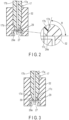
- the second embodiment shown in FIG. 3 is different from the first embodiment in that uneven portions 39 are formed on the side surface 17d of the high voltage cable 17 of the first embodiment shown in FIG. 2 .
- the uneven portions 39 are formed by sandblasting in the second embodiment, but may be formed by scraping or the like.
- the third embodiment shown in FIG. 4 is different from the first embodiment in that the side surface 17d continuous with the distal end surface 17c of the high voltage cable 17 of the first embodiment shown in FIG. 2 is formed into a circular arc shape.
- the angle R formed between the contact surface 29a of the power feed section 29 and the side surface 17d of the high voltage cable 17 can be made an acute angle even smaller than that of the first embodiment.
- the arc shape of the side surface 17d continuous with the distal end surface 17c can be easily formed by cutting.
- this invention is not limited to the above embodiments as it is, but can be embodied in the implementation stage by transforming the component elements to the extent not to depart from the gist thereof. Also, various inventions can be formed by appropriate combinations of the plurality of components disclosed in the above embodiments. For example, some components may be deleted from all the components shown in the embodiments.
- an uneven portion 39 may be formed on the side surface 17d in contact with the cable-side insulation material 32.
- adhesion with the cable-side insulation material 32 can be improved.
- the distal end surface 17c and the side surface 17d may as well be made into a hemispherical surface shape as a whole.
Landscapes
- X-Ray Techniques (AREA)
Abstract
Description
- Embodiments described herein relate generally to an X-ray tube.
- Generally, as X-ray tubes, fixed anode X-ray tubes are known.
- The fixed anode X-ray tubes comprise a vacuum enclosure, an anode target, a cathode filament, a power feed section, a high-voltage cable connected to the power feed section, and an insulating section which covers the power feed section and the high-voltage cable with insulating material. A flat portion at one end of the vacuum enclosure has an output window that transmits X-rays.
- The anode target is located inside the vacuum enclosure so as to oppose the output window. The cathode filament is located inside the vacuum enclosure and emits electrons to be irradiated onto the anode target.
- To the power feed section, the high-voltage cable that supplies high voltage to the anode target is connected, and the area around the power feed section and the high-voltage cable is covered by an insulating material.
- Patent Literature 1:
US 6,440,192 B - However, during the manufacturing process of X-ray tubes and during use in the market, defects such as cracks, voids (cavities), exfoliation and the like occur in the insulation material provided around the power feed section and the high-voltage cable, and thus, the performance of the voltage withstand of the X-ray tube deteriorates undesirably.
- The embodiments have been achieved in consideration of the above-provided points, and an object thereof is to provide an X-ray tube that can prevent a decrease in voltage holding capability.
- In order to solve the above problems, an X-ray tube of one embodiment includes a vacuum enclosure in which an output window which transmits X-rays is formed, an anode target provided in the vacuum enclosure so as to oppose the output window, a cathode filament provided in the vacuum enclosure, that emits electrons to be irradiated onto the anode target, a power feed section to which a high voltage cable is connected to supply high voltage to the anode target, and an insulating portion that covers the power feed section and the high-voltage cable with an insulating material, and the power feed section includes a contact surface with which a distal end surface of the high-voltage cable is brought into contact, and an angle formed by the contact surface and the side surface of the high-voltage cable is an acute angle.
-
-
FIG. 1 is a cross-sectional view schematically showing a configuration of an X-ray tube according to the first embodiment. -
FIG. 2 is a cross-sectional view focusing on a joint portion between the power feed section and the high-voltage cable shown inFIG. 1 and its surrounding area. -
FIG. 3 is a cross-sectional view of a portion corresponding to that ofFIG. 2 according to the second embodiment. -
FIG. 4 is a cross-sectional view of a portion corresponding to that ofFIG. 2 according to the third embodiment. - The X-ray tube of the first embodiment will be described in detail with reference to the accompanying drawings.
- As shown in
FIG. 1 , the X-ray tube 1 of the first embodiment is a fixed anode type X-ray tube and comprises avacuum enclosure 3, ananode target 5, asupport 7, a cathode filament 9, aninsulating enclosure 11, atube container 13, aheat radiator 15, and ahigh voltage cable 17. - The
vacuum enclosure 3 maintains a vacuum inside and has a cylindrical shape with a distal end portion whose outer diameter gradually tapering down, which includes anoutput window 19 that transmits X-rays on a flat portion of a distal end surface thereof. - The
output window 19 is made of beryllium (Be), for example, as a material with low attenuation of X-rays. - Inside the
vacuum enclosure 3, theanode target 5 is placed to oppose theoutput window 19, and the cathode filament 9 is placed on an outer circumferential side of theanode target 5. Note that a convergingelectrode 21 is provided between theanode target 5 and the cathode filament 9. - Further, in a central portion of the
vacuum enclosure 3, adistal end portion 7a of thesupport 7 is located. Thedistal end portion 7a of thesupport 7 is disposed on an inner circumferential side of the convergingelectrode 21 and supports theanode target 5 by the distal end. Theother end portion 7b of thesupport 7 protrudes from the other end side of theinsulating enclosure 11, and a joint member (an anode-side metal enclosure) 23 is brazed thereto. Thus, theinsulating enclosure 11 and thesupport 7 jointed together in a sealed state by thejoint member 23. - A
metal film 36 is formed on a distal end surface (one end surface) 11b of theinsulating enclosure 11, and a cathode-side metal enclosure 24, which supports the cathode filament 9, is brazed to themetal film 36. - On the end surface of the
other end portion 7b of thesupport 7, anexhaust pipe 27 is provided to exhaust the inside of thevacuum enclosure 3 through anexhaust channel 25 formed inside thesupport 7, and further, apower feed section 29 is provided, to which thehigh voltage cable 17 is connected to apply high voltage to theanode target 5. - The insulating
heat radiator 15 has a female threaded portion, which is tightened to a male threaded portion formed on theother end portion 7b of thesupport 7, and one end surface thereof is brought into contact with thejoint member 23. - The
heat radiator 15 is ceramics having high thermal conductivity characteristics of 20 W/m·K or higher and high voltage insulation of 10 kV/mm or higher, and when, for example, aluminum nitride is used, a high thermal conductivity of 90 W/m·K or higher can be achieved. - As shown in
FIG. 2 , thepower feed section 29 includes acontact surface 29a with which thehigh voltage cable 17 is brought into contact, and thecontact surface 29a is a flat surface. - As shown in
FIG. 1 , the high-voltage cable 17 is located on the inner circumferential side of theheat radiator 15 and is drawn out of theheat radiator 15. The high-voltage cable 17 is constituted by acore material 17a and a silicon resin-madecoating material 17b that covers thecore material 17a. - Between the high-
voltage cable 17 and theheat radiator 15, a cable-side insulating material 32 is filled. - The
insulating enclosure 11, whose interior is vacuumed together with thevacuum enclosure 3, theother end portion 7b of thesupport 7, which protrudes from theinsulating enclosure 11, a part of theheat radiator 15 and the like are accommodated in thetube container 13. The interior of thetube container 13 is filled with aninsulating material 33 of the inner side of the tube. In more detail, the tube inner-sideinsulating material 33 is filled between thetube container 13 and theinsulating enclosure 11, thejoint member 23 and theheat radiator 15. - Note that the cable
side insulation material 32 and the tube inner-side insulation material 33 are, for example, potting materials such as of silicone resin. - A
cooling section 35 is arranged on the outer surface of thetube container 13. For thiscooling section 35, an air-cooling type, a liquid-cooling type, or a heat pipe type, for example, can be selected according to the input of the X-ray tube 1, but the air-cooling type or the heat pipe type, which is easier to maintain and manage, is preferred. The cooling section may be a radiator. - By the impact of electrons on the
anode target 5, heat is generated, and the heat of theanode target 5 is transferred to thesupport 7, then dissipated and conducted through thejoint member 23 connected to theother end portion 7b of thesupport 7 to theinsulating enclosure 11, theinsulating materials heat radiator 15. Further, the heat is dissipated and conducted through theheat radiator 15 to theinsulating materials tube container 13 and the like. The heat conducted from theinsulating materials heat radiator 15 to thetube container 13 is released by thecooling section 35 that cools the outer surface of thetube container 13. In this embodiment, theheat radiator 15 is directly connected to theother end portion 7b of thesupport 7, and therefore the heat generated by theanode target 5 and transferred to thesupport 7 can be released more efficiently. - Here, the joint portion between the high-
voltage cable 17 and thepower feed section 29 will now be explained. As shown inFIG. 2 , thedistal end surface 17c of the high-voltage cable 17 is a flat surface and is in contact with thecontact surface 29a of thepower feed section 29. - A
side surface 17d of the high-voltage cable 17 is formed into a tapered shape whose diameter gradually decreases towards adistal end surface 17c side. - An angle R formed between the
contact surface 29a of thepower feed section 29 and theside surface 17d of thehigh voltage cable 17 is an acute angle, and the angle R should preferably be 10 to 80 degrees, more preferably, 20 to 60 degrees. - By joining the high-
voltage cable 17 and thepower feed section 29 together at an acute angle R, the following advantage can be obtained. That is, when the cable-side insulation material 32 is filled between theside surface 17d of the high-voltage cable 17 and thepower feed section 29 in the manufacturing process of the X-ray tube 1, the residual stress generated inside the cable-side insulation material 32 between theside surface 17d of the high-voltage cable 17 and thecontact surface 29a of thepower feed section 29 can be relaxed in a series of processing steps including injection of the cableside insulation material 32, curing by heating and cooling. - By relaxing the residual stress in the cable-
side insulation material 32, the cracks, voids and exfoliation, which may occur inside the cable-side insulation material 32 can be suppressed, and thus the voltage withstanding performance at the joint portion between thehigh voltage cable 17 and thepower feed section 29 can be maintained, thereby making it possible to obtain a highly reliable X-ray tube 1. - Further, according to this embodiment, the
side surface 17d of the high-voltage cable 17 is simply formed into a tapered shape, and thus it can be easily achieved by cutting or the like. - Other embodiments will be described below. In the embodiments described below, parts that have the same effects as those of the embodiment described above will be marked with the same symbols, and detailed descriptions of those parts will be omitted. The following descriptions will be provided for points that differ mainly from those of the above-provided embodiment.
- The second embodiment shown in
FIG. 3 is different from the first embodiment in thatuneven portions 39 are formed on theside surface 17d of thehigh voltage cable 17 of the first embodiment shown inFIG. 2 . - The
uneven portions 39 are formed by sandblasting in the second embodiment, but may be formed by scraping or the like. - According to this second embodiment, advantageous effects similar to those of the first embodiment described above can be achieved. In addition, with the
uneven portions 39 thus formed on the side surface of the high-voltage cable 17, the surface area where the high-voltage cable 17 is in contact with the cable-side insulation material 32 is increased, and the adhesiveness with the cable-side insulation material 32 can be improved. - The third embodiment shown in
FIG. 4 is different from the first embodiment in that theside surface 17d continuous with thedistal end surface 17c of thehigh voltage cable 17 of the first embodiment shown inFIG. 2 is formed into a circular arc shape. - According to this third embodiment, advantageous effects similar to those of the first embodiment described above can be achieved. In addition, with the
side surface 17d continuous with thedistal end surface 17c formed into an arc shape, the angle R formed between thecontact surface 29a of thepower feed section 29 and theside surface 17d of thehigh voltage cable 17 can be made an acute angle even smaller than that of the first embodiment. - The arc shape of the
side surface 17d continuous with thedistal end surface 17c can be easily formed by cutting. - Note that this invention is not limited to the above embodiments as it is, but can be embodied in the implementation stage by transforming the component elements to the extent not to depart from the gist thereof. Also, various inventions can be formed by appropriate combinations of the plurality of components disclosed in the above embodiments. For example, some components may be deleted from all the components shown in the embodiments.
- In the high-
voltage cable 17 of the third embodiment, as in the second embodiment, anuneven portion 39 may be formed on theside surface 17d in contact with the cable-side insulation material 32. In this case, as in the second embodiment, adhesion with the cable-side insulation material 32 can be improved. - Note that in the
high voltage cable 17 of the third embodiment, thedistal end surface 17c and theside surface 17d may as well be made into a hemispherical surface shape as a whole.
Claims (3)
- An X-ray tube comprising:a vacuum enclosure in which an output window which transmits X-rays is formed;an anode target provided in the vacuum enclosure so as to oppose the output window;a cathode filament provided in the vacuum enclosure, that emits electrons to be irradiated onto the anode target;a power feed section to which a high voltage cable is connected to supply high voltage to the anode target;an insulating portion that covers the power feed section and the high-voltage cable with an insulating material,whereinthe power feed section includes a contact surface with which a distal end surface of the high-voltage cable is brought into contact, andan angle formed by the contact surface and the side surface of the high-voltage cable is an acute angle.
- The X-ray tube according to claim 1, wherein the side surface of the high voltage cable is formed into a tapered shape, a diameter of which is gradually decreased on a side of the distal end surface.
- The X-ray tube according to claim 1 or 2, wherein
the side surface of the high voltage cable is formed into an uneven surface.
Applications Claiming Priority (2)
| Application Number | Priority Date | Filing Date | Title |
|---|---|---|---|
| JP2020211339A JP2022098027A (en) | 2020-12-21 | 2020-12-21 | X-ray tube |
| PCT/JP2021/019174 WO2022137592A1 (en) | 2020-12-21 | 2021-05-20 | X-ray tube |
Publications (2)
| Publication Number | Publication Date |
|---|---|
| EP4266345A1 true EP4266345A1 (en) | 2023-10-25 |
| EP4266345A4 EP4266345A4 (en) | 2024-11-13 |
Family
ID=82158887
Family Applications (1)
| Application Number | Title | Priority Date | Filing Date |
|---|---|---|---|
| EP21909753.2A Pending EP4266345A4 (en) | 2020-12-21 | 2021-05-20 | X-ray tube |
Country Status (6)
| Country | Link |
|---|---|
| US (1) | US12484135B2 (en) |
| EP (1) | EP4266345A4 (en) |
| JP (1) | JP2022098027A (en) |
| KR (1) | KR20230093334A (en) |
| CN (1) | CN116648770A (en) |
| WO (1) | WO2022137592A1 (en) |
Family Cites Families (15)
| Publication number | Priority date | Publication date | Assignee | Title |
|---|---|---|---|---|
| JPS50148974U (en) * | 1974-05-29 | 1975-12-10 | ||
| JPH04137372A (en) * | 1990-09-26 | 1992-05-12 | Toshiba Corp | High voltage member insulating structure |
| DE9313823U1 (en) | 1993-09-13 | 1993-11-11 | Patent-Treuhand-Gesellschaft für elektrische Glühlampen mbH, 81543 München | Electric lamp |
| JPH08236246A (en) * | 1995-02-28 | 1996-09-13 | Showa Electric Wire & Cable Co Ltd | Formation of connection part of cross-linked polyolefin-insulated cable |
| FR2761901B1 (en) | 1997-04-10 | 1999-05-14 | Valeo | METHOD FOR PRODUCING A FILTERING DEVICE AND FILTERING DEVICE IN PARTICULAR FOR AERATION AND / OR AIR CONDITIONING OF PREMISES OR VEHICLES |
| JPH1118240A (en) * | 1997-06-25 | 1999-01-22 | Mitsubishi Cable Ind Ltd | Clean room for assembling connection for power cable |
| JP4279994B2 (en) * | 2001-01-22 | 2009-06-17 | 株式会社東芝 | X-ray tube device |
| JP2007042434A (en) * | 2005-08-03 | 2007-02-15 | Toshiba Corp | X-ray tube |
| JP4850542B2 (en) * | 2006-03-10 | 2012-01-11 | 浜松ホトニクス株式会社 | Electron gun, energy beam generator, electron beam generator, and X-ray generator |
| JP5196872B2 (en) * | 2007-05-28 | 2013-05-15 | 株式会社東芝 | High voltage connector for X-ray tube |
| JP5039080B2 (en) * | 2009-03-24 | 2012-10-03 | 株式会社Ihiインフラシステム | Cable end tension releasing method and cable clamp device used for carrying out the method |
| JP2010244709A (en) * | 2009-04-01 | 2010-10-28 | Toshiba Corp | X-ray tube device |
| US8817950B2 (en) | 2011-12-22 | 2014-08-26 | Moxtek, Inc. | X-ray tube to power supply connector |
| DE102014015974B4 (en) * | 2014-10-31 | 2021-11-11 | Baker Hughes Digital Solutions Gmbh | Connection cable for reducing flashover-induced transient electrical signals between the acceleration section of an X-ray tube and a high-voltage source |
| JP6440192B2 (en) * | 2015-01-14 | 2018-12-19 | キヤノン電子管デバイス株式会社 | X-ray tube |
-
2020
- 2020-12-21 JP JP2020211339A patent/JP2022098027A/en active Pending
-
2021
- 2021-05-20 KR KR1020237018400A patent/KR20230093334A/en not_active Ceased
- 2021-05-20 WO PCT/JP2021/019174 patent/WO2022137592A1/en not_active Ceased
- 2021-05-20 EP EP21909753.2A patent/EP4266345A4/en active Pending
- 2021-05-20 CN CN202180085724.9A patent/CN116648770A/en active Pending
-
2023
- 2023-06-20 US US18/337,558 patent/US12484135B2/en active Active
Also Published As
| Publication number | Publication date |
|---|---|
| EP4266345A4 (en) | 2024-11-13 |
| CN116648770A (en) | 2023-08-25 |
| JP2022098027A (en) | 2022-07-01 |
| US20230337348A1 (en) | 2023-10-19 |
| WO2022137592A1 (en) | 2022-06-30 |
| US12484135B2 (en) | 2025-11-25 |
| KR20230093334A (en) | 2023-06-27 |
Similar Documents
| Publication | Publication Date | Title |
|---|---|---|
| US8761345B2 (en) | X-ray tube | |
| EP2547177B1 (en) | Radiation generating apparatus and radiation imaging apparatus | |
| EP0168641B1 (en) | X-ray tube | |
| US9373478B2 (en) | Radiation generating apparatus and radiation imaging apparatus | |
| JP2020523760A (en) | X-ray source and method of manufacturing X-ray source | |
| CN101952907B (en) | High voltage insulation device | |
| US11875965B2 (en) | X-ray tube | |
| US6798865B2 (en) | HV system for a mono-polar CT tube | |
| JP2015232944A (en) | X-ray tube device | |
| US12484135B2 (en) | X-ray tube | |
| US11756760B2 (en) | X-ray tube having an insulation body with a potted body | |
| JP2015230754A (en) | X-ray tube device | |
| US9728369B2 (en) | Two-part high voltage vacuum feed through for an electron tube | |
| JP2011108415A (en) | X-ray tube device and manufacturing method of x-ray tube device | |
| JP6440192B2 (en) | X-ray tube | |
| JP2010080347A (en) | Fixed anode x-ray tube device | |
| JP2010055891A (en) | Fixed positive electrode type x-ray tube device | |
| JP2006012591A (en) | Fixed anode x-ray tube device | |
| EP2873086B1 (en) | Cooling arrangement for x-ray generator | |
| JP2009289462A (en) | Fixed-anode x-ray tube device | |
| JP2015216041A (en) | X-ray tube apparatus and manufacturing method thereof | |
| JP2007042434A (en) | X-ray tube | |
| JP2021096951A (en) | Cathode structure | |
| JP2024036919A (en) | X-ray tube device | |
| JP2024003557A (en) | Method for manufacturing x-ray tube |
Legal Events
| Date | Code | Title | Description |
|---|---|---|---|
| STAA | Information on the status of an ep patent application or granted ep patent |
Free format text: STATUS: THE INTERNATIONAL PUBLICATION HAS BEEN MADE |
|
| PUAI | Public reference made under article 153(3) epc to a published international application that has entered the european phase |
Free format text: ORIGINAL CODE: 0009012 |
|
| STAA | Information on the status of an ep patent application or granted ep patent |
Free format text: STATUS: REQUEST FOR EXAMINATION WAS MADE |
|
| 17P | Request for examination filed |
Effective date: 20230619 |
|
| AK | Designated contracting states |
Kind code of ref document: A1 Designated state(s): AL AT BE BG CH CY CZ DE DK EE ES FI FR GB GR HR HU IE IS IT LI LT LU LV MC MK MT NL NO PL PT RO RS SE SI SK SM TR |
|
| DAV | Request for validation of the european patent (deleted) | ||
| DAX | Request for extension of the european patent (deleted) | ||
| A4 | Supplementary search report drawn up and despatched |
Effective date: 20241014 |
|
| RIC1 | Information provided on ipc code assigned before grant |
Ipc: H01J 35/08 20060101AFI20241008BHEP |