EP4266517A1 - Système de câble supraconducteur triphasé à redondance - Google Patents
Système de câble supraconducteur triphasé à redondance Download PDFInfo
- Publication number
- EP4266517A1 EP4266517A1 EP22305601.1A EP22305601A EP4266517A1 EP 4266517 A1 EP4266517 A1 EP 4266517A1 EP 22305601 A EP22305601 A EP 22305601A EP 4266517 A1 EP4266517 A1 EP 4266517A1
- Authority
- EP
- European Patent Office
- Prior art keywords
- superconducting cable
- phase
- coolant
- cryogenic
- envelopes
- Prior art date
- Legal status (The legal status is an assumption and is not a legal conclusion. Google has not performed a legal analysis and makes no representation as to the accuracy of the status listed.)
- Pending
Links
Images
Classifications
-
- H—ELECTRICITY
- H01—ELECTRIC ELEMENTS
- H01B—CABLES; CONDUCTORS; INSULATORS; SELECTION OF MATERIALS FOR THEIR CONDUCTIVE, INSULATING OR DIELECTRIC PROPERTIES
- H01B12/00—Superconductive or hyperconductive conductors, cables, or transmission lines
- H01B12/02—Superconductive or hyperconductive conductors, cables, or transmission lines characterised by their form
- H01B12/04—Single wire
-
- H—ELECTRICITY
- H02—GENERATION; CONVERSION OR DISTRIBUTION OF ELECTRIC POWER
- H02H—EMERGENCY PROTECTIVE CIRCUIT ARRANGEMENTS
- H02H9/00—Emergency protective circuit arrangements for limiting excess current or voltage without disconnection
- H02H9/02—Emergency protective circuit arrangements for limiting excess current or voltage without disconnection responsive to excess current
- H02H9/023—Current limitation using superconducting elements
-
- H—ELECTRICITY
- H01—ELECTRIC ELEMENTS
- H01B—CABLES; CONDUCTORS; INSULATORS; SELECTION OF MATERIALS FOR THEIR CONDUCTIVE, INSULATING OR DIELECTRIC PROPERTIES
- H01B12/00—Superconductive or hyperconductive conductors, cables, or transmission lines
- H01B12/16—Superconductive or hyperconductive conductors, cables, or transmission lines characterised by cooling
-
- H—ELECTRICITY
- H01—ELECTRIC ELEMENTS
- H01R—ELECTRICALLY-CONDUCTIVE CONNECTIONS; STRUCTURAL ASSOCIATIONS OF A PLURALITY OF MUTUALLY-INSULATED ELECTRICAL CONNECTING ELEMENTS; COUPLING DEVICES; CURRENT COLLECTORS
- H01R4/00—Electrically-conductive connections between two or more conductive members in direct contact, i.e. touching one another; Means for effecting or maintaining such contact; Electrically-conductive connections having two or more spaced connecting locations for conductors and using contact members penetrating insulation
- H01R4/58—Electrically-conductive connections between two or more conductive members in direct contact, i.e. touching one another; Means for effecting or maintaining such contact; Electrically-conductive connections having two or more spaced connecting locations for conductors and using contact members penetrating insulation characterised by the form or material of the contacting members
- H01R4/68—Connections to or between superconductive connectors
-
- H—ELECTRICITY
- H02—GENERATION; CONVERSION OR DISTRIBUTION OF ELECTRIC POWER
- H02G—INSTALLATION OF ELECTRIC CABLES OR LINES, OR OF COMBINED OPTICAL AND ELECTRIC CABLES OR LINES
- H02G15/00—Cable fittings
- H02G15/34—Cable fittings for cryogenic cables
-
- H—ELECTRICITY
- H02—GENERATION; CONVERSION OR DISTRIBUTION OF ELECTRIC POWER
- H02H—EMERGENCY PROTECTIVE CIRCUIT ARRANGEMENTS
- H02H7/00—Emergency protective circuit arrangements specially adapted for specific types of electric machines or apparatus or for sectionalised protection of cable or line systems, and effecting automatic switching in the event of an undesired change from normal working conditions
- H02H7/001—Emergency protective circuit arrangements specially adapted for specific types of electric machines or apparatus or for sectionalised protection of cable or line systems, and effecting automatic switching in the event of an undesired change from normal working conditions for superconducting apparatus, e.g. coils, lines, machines
-
- H—ELECTRICITY
- H02—GENERATION; CONVERSION OR DISTRIBUTION OF ELECTRIC POWER
- H02J—ELECTRIC POWER NETWORKS; CIRCUIT ARRANGEMENTS OR SYSTEMS FOR SUPPLYING OR DISTRIBUTING ELECTRIC POWER; SYSTEMS FOR STORING ELECTRIC ENERGY
- H02J3/00—Circuit arrangements for AC mains or AC distribution networks
- H02J3/36—Arrangements for transfer of electric power between AC networks via high-voltage DC [HVDC] links; Arrangements for transfer of electric power between generators and networks via HVDC links
-
- Y—GENERAL TAGGING OF NEW TECHNOLOGICAL DEVELOPMENTS; GENERAL TAGGING OF CROSS-SECTIONAL TECHNOLOGIES SPANNING OVER SEVERAL SECTIONS OF THE IPC; TECHNICAL SUBJECTS COVERED BY FORMER USPC CROSS-REFERENCE ART COLLECTIONS [XRACs] AND DIGESTS
- Y02—TECHNOLOGIES OR APPLICATIONS FOR MITIGATION OR ADAPTATION AGAINST CLIMATE CHANGE
- Y02E—REDUCTION OF GREENHOUSE GAS [GHG] EMISSIONS, RELATED TO ENERGY GENERATION, TRANSMISSION OR DISTRIBUTION
- Y02E40/00—Technologies for an efficient electrical power generation, transmission or distribution
- Y02E40/60—Superconducting electric elements or equipment; Power systems integrating superconducting elements or equipment
Definitions
- the present invention relates to superconducting cable systems, in particular to 3-phase superconducting cable systems in which conductors of each phase of the cable system run in separate cryostats.
- Low-temperature superconductors typically metallic superconductors
- High temperature superconductors typically ceramic superconductors
- LN2 liquid Nitrogen
- any phase conductor of 3-phase superconducting cables can be damaged at any time. This damage can be electrical, or hydraulic if there is a leak in the cryogenic envelope in which the coolant circulates. Repairs are time consuming, or in some cases not possible, so that components must be replaced. During this time, the entire 3-phase superconducting cable system cannot be operated.
- an object of the present invention to provide a superconducting cable system that can continue operation while one conductor or its cryogenic envelope is damaged or broken.
- a 3-phase superconducting cable system in accordance with a first aspect of the invention comprises four 1-phase superconducting cables, of which a first, a second and a third are electrically connected with a corresponding first, second and third electrical phase.
- Interrupting switches are arranged at respective first and second ends of a first, second and third of the 1-phase superconducting cables.
- First connecting switches and second connecting switches are connected at a first and a second end, respectively, of the fourth 1-phase superconducting cable in such a way, that a switchable connection between the first and second ends of the fourth superconducting cable and corresponding ends of each of the first, second and third superconducting cables exists.
- the interrupting switches and the first and second connecting switches are operable to selectively disconnect one of the first, second or third of the 1-phase superconducting cables from their respective current phase and to connect the fourth 1-phase superconducting cable to the previously disconnected current phase, effectively replacing the disconnected 1-phase superconducting cable.
- each of the four 1-phase superconducting cables runs in a separate cryogenic envelope, and each of the separate cryogenic envelopes has shut-off valves at the respective first and second ends.
- At least a first cooling system which feeds coolant into a first end of at least a first one of the four cryogenic envelopes, and receives coolant from a first end of at least a second one of the four cryogenic envelopes.
- the second ends of the cryogenic envelopes are connected to a coolant router which is adapted to receive coolant from at least one of the four cryogenic envelopes and to feed coolant into at least another one of the four cryogenic envelopes.
- a second cooling system which is adapted to receive coolant from the second ends of cryogenic envelopes coolant-fed by the first cooling system at their respective first ends, and which is adapted to feed coolant into the second ends of cryogenic envelopes, from which the first cooling unit receives coolant at their respective first ends.
- a spare coolant line is provided between first cooling system and the coolant router or the second cooling system, respectively.
- the spare coolant line preferably has a the same hydraulic cross section or hydraulic properties as the cryogenic envelope of a superconducting cable.
- each end of the four 1-phase superconducting cables is electrically shielded, and the shields are switchably connected to ground, at each respective end.
- a method of operating a 3-phase superconducting cable system in accordance with the first aspect of the invention comprises detecting a damage to one of the first, second or third superconducting cable. If such damage is detected, the interrupting switches at the first and second end of the damaged superconducting cable are operated, for disconnecting it from the associated electrical phase. At the same time, or in a close temporal context, the respective first and second connecting switches associated with the damaged superconducting cable are operated, for connecting the fourth superconducting cable to the disconnected electrical phase.
- the close temporal context may comprise connecting the fourth superconducting cable to the disconnected electrical phase prior to disconnecting the damaged superconducting cable.
- Disconnecting the damaged superconducting cable and connecting the fourth superconducting cable may comprise disconnecting and connecting the corresponding electrical shields.
- the coolant will flow through all of the cryogenic envelopes, preferably symmetrically distributed.
- the method further comprises closing the shut-off valves at both ends of the cryogenic envelope of the damaged superconducting cable.
- the damaged superconductor will then warm up and can be repaired or replaced.
- the method further comprises if properties of a coolant flowing out of the first cooling system and/or into the first cooling system meet or exceed predetermined limit values. If the limit values are not met the method further comprises connecting the first cooling system and the coolant router, or the first cooling system and the second cooling system via a spare coolant line.
- the limit values may relate to one or more of a minimum flow, a maximum coolant return temperature, or the like. This embodiment permits compensating for an asymmetric coolant flow caused by closing the shut-off valves at both ends of the cryogenic envelope of the damaged superconducting cable, which otherwise would be symmetrically distributed over the cryogenic envelopes of the four superconducting cables in case the required low temperatures cannot be maintained through the asymmetric coolant flow.
- the superconducting cable system presented hereinbefore permits uninterrupted operation when one of the cables is damaged.
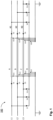
- FIG. 1 shows a schematic diagram of the electrical connections of an exemplary superconducting cable system 100.
- Phases L1 to L3 are connected to first ends of first, second and third superconducting cables A, B, and C via respective switches S1, S3, and S5.
- Switches S2, S4 and S6 at the second ends of the first, second and third superconducting cables A, B, and C permit connecting the phases L1 to L3 to conventional cables K1, K2 and K3, downstream of the superconducting cables A, B, and C.
- One of switches S7, S9, and S11 connects each of the phases L1 to L3 to a first end of a fourth superconducting cable D.
- Switches S8, S10, and S12 connect the second end of the fourth superconducting cable D to respective conventional cables K1, K2 and K3, downstream of switches S2, S4 and S6.
- Switches GS1, GS3, GS5, and GS7 connect respective electrical shields at the first end of the first through fourth superconducting cables A, B, C, and D to ground, and switches GS2, GS4, GS6, and GS8 connect respective electrical shields at the second end of the first through fourth superconducting cables A, B, C, and D to ground.
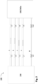
- FIG. 2 shows a schematic diagram of a cooling arrangement of the exemplary superconducting cable system 100.
- Shut-off valves V1, V3, V5, and V7 are provided at first ends of the cryogenic envelopes of the first through fourth superconducting cables A, B, C and D.
- the shut-off valves V1, V3, V5, and V7 connect the cryogenic envelopes to a first cooling system 200, which provides a coolant flow through two of the cryogenic envelopes, in the figure those of the superconducting cables A and B, and receives a coolant flow through two other of the cryogenic envelopes, in the figure those of the superconducting cables C and D.
- the coolant flow direction is indicated by the arrows.
- Shut-off valves V2, V4, V6, and V8 provided at second ends of the cryogenic envelopes of the first through fourth superconducting cables A, B, C and D are connected to a second cooling system 300 or to a coolant router 300a.
- the second cooling system 300 or the coolant router 300a receive a coolant flow from the first cooling system 200 through two of the cryogenic envelopes and return a coolant flow to the first cooling system 200 through two other of the cryogenic envelopes.
- the coolant flow is symmetric, as the cryogenic envelopes have identical identical hydraulic cross sections or hydraulic properties and two cryogenic envelopes carry coolant from the first cooling system 200 to the second cooling system 300 or the coolant router 300a, and two other cryogenic envelopes carry coolant from the second cooling system 300 or the coolant router 300a to the first cooling system 200.
- the required low temperature within the cryogenic envelopes may be maintained using only three cryogenic envelopes in an asymmetric way.
- the asymmetry may be compensated for by the spare coolant line R. It is to be noted that the spare coolant line R can operate in either direction.
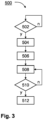
- FIG. 3 shows a flow diagram of an exemplary method of operating the exemplary superconducting cable system 100.
- a periodic or continuous damage detection is carried out and looped back in the "no"-branch of step 502.
- "yes"-branch of step 502 the corresponding interrupting switches S1, S2, S3, S4, S5, S6 at both ends of the damaged superconducting cable or its cryogenic envelope are operated, in step 504, for disconnecting it from the associated electrical phase (L1, L2, L3).
- the corresponding valves of the damaged superconducting cable or its cryogenic envelope are closed, allowing the superconducting cable to warm up and be accessible for repair or replacement.
- step 508 the respective first and second connecting switches associated with the damaged superconducting cable are closed, for connecting the fourth superconducting cable to the disconnected electrical phase.
- step 510 the method determines, continuously or periodically, if properties of a coolant flow out of the first cooling system 200 and/or into the first cooling system 200 meet or exceed predetermined limit values. In the positive case, "yes"-branch of step 510, the first cooling system 200 and the coolant router 300a, or the first cooling system 200 and the second cooling system 300, are connected, in step 512, via spare coolant line R.
Landscapes
- Physics & Mathematics (AREA)
- Condensed Matter Physics & Semiconductors (AREA)
- General Physics & Mathematics (AREA)
- Engineering & Computer Science (AREA)
- Power Engineering (AREA)
- Superconductors And Manufacturing Methods Therefor (AREA)
Priority Applications (2)
| Application Number | Priority Date | Filing Date | Title |
|---|---|---|---|
| EP22305601.1A EP4266517A1 (fr) | 2022-04-22 | 2022-04-22 | Système de câble supraconducteur triphasé à redondance |
| US18/138,023 US20230411045A1 (en) | 2022-04-22 | 2023-04-21 | 3-phase superconducting cable system with redundancy |
Applications Claiming Priority (1)
| Application Number | Priority Date | Filing Date | Title |
|---|---|---|---|
| EP22305601.1A EP4266517A1 (fr) | 2022-04-22 | 2022-04-22 | Système de câble supraconducteur triphasé à redondance |
Publications (1)
| Publication Number | Publication Date |
|---|---|
| EP4266517A1 true EP4266517A1 (fr) | 2023-10-25 |
Family
ID=81580602
Family Applications (1)
| Application Number | Title | Priority Date | Filing Date |
|---|---|---|---|
| EP22305601.1A Pending EP4266517A1 (fr) | 2022-04-22 | 2022-04-22 | Système de câble supraconducteur triphasé à redondance |
Country Status (2)
| Country | Link |
|---|---|
| US (1) | US20230411045A1 (fr) |
| EP (1) | EP4266517A1 (fr) |
Citations (3)
| Publication number | Priority date | Publication date | Assignee | Title |
|---|---|---|---|---|
| US20080190637A1 (en) * | 2007-02-09 | 2008-08-14 | Folts Douglas C | Fault Current Limiting HTS Cable and Method of Configuring Same |
| US20120236440A1 (en) * | 2011-03-16 | 2012-09-20 | Varian Semiconductor Equipment Associates, Inc. | Superconducting Fault Current Limiter System |
| US20120295792A1 (en) * | 2010-08-13 | 2012-11-22 | Mark Stemmle | Arrangement for electrically conductively connecting two electrical units |
-
2022
- 2022-04-22 EP EP22305601.1A patent/EP4266517A1/fr active Pending
-
2023
- 2023-04-21 US US18/138,023 patent/US20230411045A1/en active Pending
Patent Citations (3)
| Publication number | Priority date | Publication date | Assignee | Title |
|---|---|---|---|---|
| US20080190637A1 (en) * | 2007-02-09 | 2008-08-14 | Folts Douglas C | Fault Current Limiting HTS Cable and Method of Configuring Same |
| US20120295792A1 (en) * | 2010-08-13 | 2012-11-22 | Mark Stemmle | Arrangement for electrically conductively connecting two electrical units |
| US20120236440A1 (en) * | 2011-03-16 | 2012-09-20 | Varian Semiconductor Equipment Associates, Inc. | Superconducting Fault Current Limiter System |
Also Published As
| Publication number | Publication date |
|---|---|
| US20230411045A1 (en) | 2023-12-21 |
Similar Documents
| Publication | Publication Date | Title |
|---|---|---|
| AU2009298856B2 (en) | Electricity transmission cooling system | |
| CN101675566B (zh) | 并联高温超导故障限流器装置 | |
| KR101858632B1 (ko) | 두 개의 전기 유닛을 전도성 연결하기 위한 장치 | |
| Yazawa et al. | Design and test results of 6.6 kV high-Tc superconducting fault current limiter | |
| US20060283620A1 (en) | Method and apparatus for cooling a superconducting cable | |
| US10133242B2 (en) | Method of transmitting electrical energy | |
| Riemersma et al. | Application of superconducting technology to power transformers | |
| Meyerhoff | Superconducting power transmission | |
| US20110177954A1 (en) | Superconducting electricity transmission system | |
| GB2026776A (en) | Improvements in or relating to Superconducting Magnetic Systems | |
| US5859386A (en) | Superconductive electrical transmission line | |
| US20230411045A1 (en) | 3-phase superconducting cable system with redundancy | |
| CN114303209A (zh) | 用于超导磁体的电流引线 | |
| Telikapalli et al. | Hts technology driven shipboard power distribution architecture–cryogenics | |
| Dixon et al. | The 36-T series-connected hybrid magnet system design and integration | |
| Forsyth | Superconducting power transmission systems-the past and possibly the future | |
| JP4409745B2 (ja) | 送変電設備 | |
| Meyerhoff | Superconducting power transmission | |
| Lierl et al. | Superconducting magnet and cryogenic system of HERA | |
| Bai et al. | Design of cryogenic system for SCH magnets | |
| Bakhos et al. | Superconducting microgrid to support transmission between solar PV farms and data centers | |
| McAshan et al. | Cryogenic Systems for the Low Field RLHC Study Cases | |
| Heiberger et al. | Demonstration of a 67 kA vapor-cooled current lead with improved thermal efficiency | |
| Feher et al. | Commissioning of the Low-$\beta $ Triplets of the Large Hadron Collider | |
| Manahan et al. | LLNL superconducting magnets test facility |
Legal Events
| Date | Code | Title | Description |
|---|---|---|---|
| STAA | Information on the status of an ep patent application or granted ep patent |
Free format text: STATUS: THE APPLICATION HAS BEEN PUBLISHED |
|
| PUAI | Public reference made under article 153(3) epc to a published international application that has entered the european phase |
Free format text: ORIGINAL CODE: 0009012 |
|
| AK | Designated contracting states |
Kind code of ref document: A1 Designated state(s): AL AT BE BG CH CY CZ DE DK EE ES FI FR GB GR HR HU IE IS IT LI LT LU LV MC MK MT NL NO PL PT RO RS SE SI SK SM TR |
|
| STAA | Information on the status of an ep patent application or granted ep patent |
Free format text: STATUS: REQUEST FOR EXAMINATION WAS MADE |
|
| 17P | Request for examination filed |
Effective date: 20240425 |
|
| RBV | Designated contracting states (corrected) |
Designated state(s): AL AT BE BG CH CY CZ DE DK EE ES FI FR GB GR HR HU IE IS IT LI LT LU LV MC MK MT NL NO PL PT RO RS SE SI SK SM TR |