EP4267422B1 - Système de commande de distribution de puissance pour véhicule électrique et procédé de diagnostic associé - Google Patents
Système de commande de distribution de puissance pour véhicule électrique et procédé de diagnostic associé Download PDFInfo
- Publication number
- EP4267422B1 EP4267422B1 EP22702943.6A EP22702943A EP4267422B1 EP 4267422 B1 EP4267422 B1 EP 4267422B1 EP 22702943 A EP22702943 A EP 22702943A EP 4267422 B1 EP4267422 B1 EP 4267422B1
- Authority
- EP
- European Patent Office
- Prior art keywords
- current
- switched
- limiting path
- limiting
- output voltage
- Prior art date
- Legal status (The legal status is an assumption and is not a legal conclusion. Google has not performed a legal analysis and makes no representation as to the accuracy of the status listed.)
- Active
Links
Images


Classifications
-
- B—PERFORMING OPERATIONS; TRANSPORTING
- B60—VEHICLES IN GENERAL
- B60L—PROPULSION OF ELECTRICALLY-PROPELLED VEHICLES; SUPPLYING ELECTRIC POWER FOR AUXILIARY EQUIPMENT OF ELECTRICALLY-PROPELLED VEHICLES; ELECTRODYNAMIC BRAKE SYSTEMS FOR VEHICLES IN GENERAL; MAGNETIC SUSPENSION OR LEVITATION FOR VEHICLES; MONITORING OPERATING VARIABLES OF ELECTRICALLY-PROPELLED VEHICLES; ELECTRIC SAFETY DEVICES FOR ELECTRICALLY-PROPELLED VEHICLES
- B60L3/00—Electric devices on electrically-propelled vehicles for safety purposes; Monitoring operating variables, e.g. speed, deceleration or energy consumption
- B60L3/04—Cutting off the power supply under fault conditions
-
- B—PERFORMING OPERATIONS; TRANSPORTING
- B60—VEHICLES IN GENERAL
- B60L—PROPULSION OF ELECTRICALLY-PROPELLED VEHICLES; SUPPLYING ELECTRIC POWER FOR AUXILIARY EQUIPMENT OF ELECTRICALLY-PROPELLED VEHICLES; ELECTRODYNAMIC BRAKE SYSTEMS FOR VEHICLES IN GENERAL; MAGNETIC SUSPENSION OR LEVITATION FOR VEHICLES; MONITORING OPERATING VARIABLES OF ELECTRICALLY-PROPELLED VEHICLES; ELECTRIC SAFETY DEVICES FOR ELECTRICALLY-PROPELLED VEHICLES
- B60L3/00—Electric devices on electrically-propelled vehicles for safety purposes; Monitoring operating variables, e.g. speed, deceleration or energy consumption
- B60L3/0023—Detecting, eliminating, remedying or compensating for drive train abnormalities, e.g. failures within the drive train
- B60L3/0038—Detecting, eliminating, remedying or compensating for drive train abnormalities, e.g. failures within the drive train relating to sensors
-
- B—PERFORMING OPERATIONS; TRANSPORTING
- B60—VEHICLES IN GENERAL
- B60L—PROPULSION OF ELECTRICALLY-PROPELLED VEHICLES; SUPPLYING ELECTRIC POWER FOR AUXILIARY EQUIPMENT OF ELECTRICALLY-PROPELLED VEHICLES; ELECTRODYNAMIC BRAKE SYSTEMS FOR VEHICLES IN GENERAL; MAGNETIC SUSPENSION OR LEVITATION FOR VEHICLES; MONITORING OPERATING VARIABLES OF ELECTRICALLY-PROPELLED VEHICLES; ELECTRIC SAFETY DEVICES FOR ELECTRICALLY-PROPELLED VEHICLES
- B60L3/00—Electric devices on electrically-propelled vehicles for safety purposes; Monitoring operating variables, e.g. speed, deceleration or energy consumption
- B60L3/0023—Detecting, eliminating, remedying or compensating for drive train abnormalities, e.g. failures within the drive train
- B60L3/0046—Detecting, eliminating, remedying or compensating for drive train abnormalities, e.g. failures within the drive train relating to electric energy storage systems, e.g. batteries or capacitors
-
- B—PERFORMING OPERATIONS; TRANSPORTING
- B60—VEHICLES IN GENERAL
- B60L—PROPULSION OF ELECTRICALLY-PROPELLED VEHICLES; SUPPLYING ELECTRIC POWER FOR AUXILIARY EQUIPMENT OF ELECTRICALLY-PROPELLED VEHICLES; ELECTRODYNAMIC BRAKE SYSTEMS FOR VEHICLES IN GENERAL; MAGNETIC SUSPENSION OR LEVITATION FOR VEHICLES; MONITORING OPERATING VARIABLES OF ELECTRICALLY-PROPELLED VEHICLES; ELECTRIC SAFETY DEVICES FOR ELECTRICALLY-PROPELLED VEHICLES
- B60L3/00—Electric devices on electrically-propelled vehicles for safety purposes; Monitoring operating variables, e.g. speed, deceleration or energy consumption
- B60L3/0023—Detecting, eliminating, remedying or compensating for drive train abnormalities, e.g. failures within the drive train
- B60L3/0069—Detecting, eliminating, remedying or compensating for drive train abnormalities, e.g. failures within the drive train relating to the isolation, e.g. ground fault or leak current
-
- B—PERFORMING OPERATIONS; TRANSPORTING
- B60—VEHICLES IN GENERAL
- B60L—PROPULSION OF ELECTRICALLY-PROPELLED VEHICLES; SUPPLYING ELECTRIC POWER FOR AUXILIARY EQUIPMENT OF ELECTRICALLY-PROPELLED VEHICLES; ELECTRODYNAMIC BRAKE SYSTEMS FOR VEHICLES IN GENERAL; MAGNETIC SUSPENSION OR LEVITATION FOR VEHICLES; MONITORING OPERATING VARIABLES OF ELECTRICALLY-PROPELLED VEHICLES; ELECTRIC SAFETY DEVICES FOR ELECTRICALLY-PROPELLED VEHICLES
- B60L3/00—Electric devices on electrically-propelled vehicles for safety purposes; Monitoring operating variables, e.g. speed, deceleration or energy consumption
- B60L3/12—Recording operating variables ; Monitoring of operating variables
-
- B—PERFORMING OPERATIONS; TRANSPORTING
- B60—VEHICLES IN GENERAL
- B60L—PROPULSION OF ELECTRICALLY-PROPELLED VEHICLES; SUPPLYING ELECTRIC POWER FOR AUXILIARY EQUIPMENT OF ELECTRICALLY-PROPELLED VEHICLES; ELECTRODYNAMIC BRAKE SYSTEMS FOR VEHICLES IN GENERAL; MAGNETIC SUSPENSION OR LEVITATION FOR VEHICLES; MONITORING OPERATING VARIABLES OF ELECTRICALLY-PROPELLED VEHICLES; ELECTRIC SAFETY DEVICES FOR ELECTRICALLY-PROPELLED VEHICLES
- B60L50/00—Electric propulsion with power supplied within the vehicle
- B60L50/50—Electric propulsion with power supplied within the vehicle using propulsion power supplied by batteries or fuel cells
- B60L50/60—Electric propulsion with power supplied within the vehicle using propulsion power supplied by batteries or fuel cells using power supplied by batteries
-
- B—PERFORMING OPERATIONS; TRANSPORTING
- B60—VEHICLES IN GENERAL
- B60L—PROPULSION OF ELECTRICALLY-PROPELLED VEHICLES; SUPPLYING ELECTRIC POWER FOR AUXILIARY EQUIPMENT OF ELECTRICALLY-PROPELLED VEHICLES; ELECTRODYNAMIC BRAKE SYSTEMS FOR VEHICLES IN GENERAL; MAGNETIC SUSPENSION OR LEVITATION FOR VEHICLES; MONITORING OPERATING VARIABLES OF ELECTRICALLY-PROPELLED VEHICLES; ELECTRIC SAFETY DEVICES FOR ELECTRICALLY-PROPELLED VEHICLES
- B60L2240/00—Control parameters of input or output; Target parameters
- B60L2240/40—Drive Train control parameters
- B60L2240/54—Drive Train control parameters related to batteries
- B60L2240/547—Voltage
-
- B—PERFORMING OPERATIONS; TRANSPORTING
- B60—VEHICLES IN GENERAL
- B60L—PROPULSION OF ELECTRICALLY-PROPELLED VEHICLES; SUPPLYING ELECTRIC POWER FOR AUXILIARY EQUIPMENT OF ELECTRICALLY-PROPELLED VEHICLES; ELECTRODYNAMIC BRAKE SYSTEMS FOR VEHICLES IN GENERAL; MAGNETIC SUSPENSION OR LEVITATION FOR VEHICLES; MONITORING OPERATING VARIABLES OF ELECTRICALLY-PROPELLED VEHICLES; ELECTRIC SAFETY DEVICES FOR ELECTRICALLY-PROPELLED VEHICLES
- B60L2270/00—Problem solutions or means not otherwise provided for
- B60L2270/20—Inrush current reduction, i.e. avoiding high currents when connecting the battery
-
- Y—GENERAL TAGGING OF NEW TECHNOLOGICAL DEVELOPMENTS; GENERAL TAGGING OF CROSS-SECTIONAL TECHNOLOGIES SPANNING OVER SEVERAL SECTIONS OF THE IPC; TECHNICAL SUBJECTS COVERED BY FORMER USPC CROSS-REFERENCE ART COLLECTIONS [XRACs] AND DIGESTS
- Y02—TECHNOLOGIES OR APPLICATIONS FOR MITIGATION OR ADAPTATION AGAINST CLIMATE CHANGE
- Y02T—CLIMATE CHANGE MITIGATION TECHNOLOGIES RELATED TO TRANSPORTATION
- Y02T10/00—Road transport of goods or passengers
- Y02T10/60—Other road transportation technologies with climate change mitigation effect
- Y02T10/70—Energy storage systems for electromobility, e.g. batteries
Definitions
- the present technology relates to a power delivery control system for an electric vehicle and to a diagnostic method therefor.
- Electric vehicles including hybrid vehicles, are becoming increasingly prevalent. Many of these vehicles comprise a large-capacity battery (or a number of battery cells effectively forming a battery), one or more electric motors operatively connected to a drivetrain, at least one power converter for adapting DC power from the battery to the specific needs of the electric motor(s), and a motor control module (MCM) controlling the power converter for driving the electric vehicle.
- a power converter may for example comprise an inverter controlled by the MCM for converting DC power from the battery to multiphase AC power delivered to an electric motor.
- the MCM controls the inverter for delivering an appropriate amount of power to the electric motor according, for example, to a position of an accelerator control of the vehicle.
- a large capacitor (or a large capacitor bank) is integrally included in the inverter, in order to compensate for reactive currents occurring in the operation of the inverter.
- Power contactors are provided between the battery and the load, the load comprising the inverter including the capacitor, and the electric motor. These power contactors are open when the vehicle is not in use, and closed when starting and operating the vehicle. Such power contactors are sturdy and are designed for withstanding the high voltage of the battery and the large current flowing between the battery and the load, for example under heavy acceleration of the vehicle. Output current levels delivered by the battery to the load may be high, sometimes over 100 amperes.
- these contactors may fail, especially when they have gone through a large number of opening and closing cycles.
- the power contactors may fail when the current level is important for an extended period.
- the power contactors may fail when they open while the current level is important, as this action may cause arcing on the contactors. Arcing may also result from bouncing of the power contactors upon closing. As a result, some power contactors may experience unintended welding and remain closed when they should be open.
- JP 2020/202646 discloses a power supply system including: a positive-electrode main contactor and a positive-electrode precharge contactor that are disposed to a positive electrode power line of a high-voltage battery in parallel to each other; a negative-electrode main contactor and a negative-electrode precharge contactor that are disposed to a negative-electrode power line of the high-voltage battery in parallel to each other; and an ECU for, when starting connection between the high-voltage battery and a load circuit, closing either one of the positive-electrode and negative-electrode main contactors after pre-charging a smoothing capacitor by closing the positive-electrode and negative-electrode precharge contactors, and then closing the other
- the present technology introduces a diagnostic method and a power delivery control system for an electric system comprising a battery and a power stage of a vehicle receiving power from the battery when power contactors therebetween are closed. Pre-charge functions are provided for initially applying a current-limited voltage from the battery to the power stage before applying a non-current-limited voltage from the battery to the power stage.
- a first pre-charge is tested between a first polarity of the battery and a first polarity of the power stage.
- a second pre-charge is then tested between a second polarity of the battery and a second polarity of the power stage. None of the first and second pre-charge tests is expected to lead to an increase of voltage on the power stage. Should the power stage voltage increase, failure of a power contactor may have been detected and a starting sequence for the electric system is aborted. On the condition that the power stage voltage does not increase in the course of the first and second pre-charge tests, an actual precharge of the power stage is performed and the power stage voltage is expected to increase.
- the diagnostic is favorable and power may be delivered to the power stage by closing the power contactors.
- the electric system may be part of the powertrain of an electric or hybrid vehicle, for example a car, a bus, a snowmobile, a motorcycle, an off-road vehicle, a kart, a boat, a drone, and the like.
- an electric or hybrid vehicle for example a car, a bus, a snowmobile, a motorcycle, an off-road vehicle, a kart, a boat, a drone, and the like.
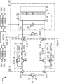
- FIG. 1 is a schematic diagram of an electric system 1 that may for example be installed in an electric (or hybrid) vehicle.
- the electric system 1 comprises a battery 10 for powering a power stage 20 of the vehicle via a contactor module 100 controlled by a motor control module (MCM) 200.
- MCM motor control module
- the battery 10 (or a plurality of batteries forming a battery bank) may be a high-voltage battery rated, for example and without limitation, at 60 volts or more. In an example application, the battery 10 may provide 350 volts at up to 40 kW, which translates to an output current of up to 114 amperes.
- Some electric vehicles may have batteries capable of delivering even more power, through higher voltages and/or higher current levels.
- the power stage 20 comprises an inverter 26 for the electric vehicle, the inverter 26 converting DC power received from the battery 10 to AC power provided to an electric motor 28 for operating the electric vehicle.
- the inverter 26 also comprises a capacitor 24 (or a plurality of capacitors forming a capacitor bank) connected to positive and negative polarities of the of the power stage 20, being thus in parallel with a power switch assembly 22.
- the power switch assembly 22 comprises a plurality of power switches (not shown) that convert DC power to AC power.
- the contactor module 100 includes an input 105 (which may also be called an input lead or an input port) connectable to a positive polarity of the battery 10, and another input 110 connectable to a negative polarity of the battery 10.
- the contactor module 100 also includes an output 115 (which may also be called an output lead or an output port) connectable to the positive polarity of the power stage 20, and another output 120 connectable to the negative polarity of the power stage 20.
- power is delivered from the battery 10 to the power stage 20 via a switched non-current-limiting path 125 extending between the input 105 and the output 110, and via a switched non-current-limiting path 130 extending between the input 110 and the output 120.
- the switched non-current-limiting path 125 may be established by closing a power contactor 135 and the switched non-current-limiting path 130 may be established by closing a power contactor 140.
- the power contactors 135 and 140 are therefore both open when the electric system 1 is not in use, and both closed when the electric system 1 is used, for example, to power the electric vehicle.
- an output voltage of the contactor module 100 between the outputs 115 and 120 is substantially equal to a voltage of the battery 10, with only insignificant voltage drops in the various components of the contactor module 100. This output voltage is thus applied on the power stage 20 of the vehicle and is present on the capacitor 24.
- the contactor module 100 also comprises a switched current-limiting path 150 that extends between the input 105 and the output 110, being therefore mounted in parallel with the switched non-current-limiting path 125.
- the contactor module 100 further comprises a switched current-limiting path 170 that extends between the input 115 and the output 120, being therefore mounted in parallel with the switched non-current-limiting path 130.
- the switched current-limiting path 150 has a resistor 155 in series with a switch 160
- the switched current-limiting path 170 has a resistor 175 in series with a switch 180.
- the resistors 155 and 175 may each have a 200 ohms resistance.
- each of the resistors 155 and 175 may be substituted with an inductance (not shown) alone or in combination with a power transistor (not shown) and a solid-state relay (not shown), a power transistor (not shown) may be gradually turned on using pulse width modulation.
- each of the switched current-limiting path 150, the switched current-limiting path 170, the switched non-current limiting path 125 and the switched non-current limiting path 130 is a normally open device, so each of these paths is open and non-conductive when the electric system 1 is inactive.
- the capacitor 24 may be pre-charged in a gradual fashion in order to avoid such potential damage.
- the inrush current may be limited by opening at least one of the switched non-current-limiting paths 125 and 130, for example by opening at least one of the power contactors 135 and 140, and by closing at least one of switched current-limiting paths 150 or 170 mounted in parallel with the open one of the switched non-current-limiting paths 125, 130, so that the current flowing between the battery 10 and the power stage 20 flows through at least one of the switched current-limiting paths 150 or 170, in which the resistor 155 or 175 limits the value of the current.
- a current may flow from a positive terminal 12 of the battery 10, through the resistor 155, the closed switch 160, the power stage 20 (including the capacitor 24), and the closed power contactor 140, returning to a negative terminal 14 of the battery 10.
- the resistor 155 should normally limit a flow of current to a safe level within this circuit, allowing to pre-charge the capacitor 24 at a gradual rate.
- the switched current-limiting path 150 may be understood as a pre-charge circuit for the capacitor 24.
- the resistor 155 will be placed in parallel with the effectively closed switched non-current-limiting path 125 and there will be no significant resistive path to reduce the inrush current flowing from the battery 10 to the power stage 20, as the battery 10 will be connected to power stage 20 at a time when it is expected to be disconnected.
- the present technology introduces a diagnostic sequence that may be executed upon starting the electric system 1 for detecting failure of one of the switched current-limiting paths 125 or 130, in particular a failure of one of the power contactors 135 or 140.
- Embodiments of the present technology further detect failure of one or the switches 160 or 180 and may further implement a self-diagnosis of the failure detection.
- the diagnostic sequence is not dependent on any particular implementation of the switched current-limiting paths 150 and 170 or on any particular implementation of the switched non-current-limiting paths 125 and 130.
- a power delivery control system comprises the contactor module 100, the MCM 200 and a voltage sensor 210, for example a voltmeter.
- the voltage sensor 210 is connected to the outputs 115 and 120 to provide an output voltage of the contactor module 100.
- the power delivery control system selectively delivers power from the battery 10 to the power stage 20 in response to a command for a start procedure received by the MCM 200.
- the MCM 200 controls operations of the switched non-current-limiting paths 125 and 130 and of the switched current-limiting paths 150 and 170 of the contactor module 100.
- the MCM 200 may also control operation of the power stage 20 of the electric vehicle.
- the MCM 200 may receive the command for the start procedure for the electric system 1 and for the vehicle from a start button 290 ( Figure 4 ) or from a start key for the vehicle. In response to the command for the start procedure, the MCM 200 may first obtain a measurement of a voltage of the battery 10 from a voltage sensor 16, for example another voltmeter, and act upon this command on the condition that the voltage of the battery 10 is deemed sufficient to operate the electrical system 1.
- the MCM 200 controls a plurality of relays operatively connected to the connector module 100.
- a first relay comprises the switch 160 actuated by a coil 220 energized by the MCM 200.
- a second relay comprises the switch 180 actuated by a coil 230 energized by the MCM 200.
- a third relay comprises the power contactor 135 actuated by a coil 240.
- a fourth relay comprises the power contactor 140 actuated by a coil 250.
- the switches 160 and 180 as well as the power contactors 135 and 140 are normally open and are therefore non-conductive when their respective coils are not energized, closing, and becoming conductive when their respective coils are energized by the MCM 200.
- normally open switches 160 and 180 and the use of normally open power contactors 135 and 140 may prevent accidentally maintaining contact between the battery 10 and the power stage 20 after shutdown of the electric system 1.
- use of dual-coil latching relays having one coil for closing and another coil for opening their contactors is also contemplated.
- the MCM 200 implements a logic for actuating the power contactors 135 and 140 as well as the switches 160 and 180 according to measurements of the output voltage of the contactor module 100 provided by the voltage sensor 210.
- the output voltage of the contactor module 100 is also a voltage applied on the capacitor 24 and on the inverter 26.
- the reported voltage may be positive or negative. Consequently, the MCM 200 may consider the magnitude of the output voltage for controlling the contactor module 100.
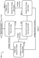
- This logic is illustrated as a simplified diagnostic sequence 300 in Figure 2 . Prior to the start of the sequence, all current-limiting and non-current limiting paths of the contactor module 100 are expected to be open and non-conductive. The diagnostic sequence 300 is intended to determine whether any one of these paths may have previously failed and are actually closed and conductive.
- Operation 310 comprises receiving, at the MCM 200, a command for a start procedure for the electric system 1.
- the non-current-limiting paths 125 and 130 and the current-limiting paths 150 and 170 should all be open. If any one of the power contactors 135 and 140 or the switches 160 and 180 is not a normally open device, the MCM 200 may cause their opening by selectively energizing and/or de-energizing their respective coils 240, 250, 220 and/or 230 before receiving the command for the start procedure, for example when shutting down the electric system 1.
- a pre-charge test of the power stage 20, for example a pre-charge test of the capacitor 24, is executed at operation 320.
- the MCM 200 closes either one of the current-limiting paths 150 or 170.
- the MCM 200 may first close the current-limiting path 150 by closing the switch 160. Once the switch 160 is closed, the MCM 200 considers a value of the output voltage of the contactor module 100 provided by the voltage sensor 210.
- both the current-limiting path 170 and the non-current-limiting 130 are open and non-conductive, no current may flow between the battery 10 and the power stage 20, and the measured output voltage should normally be lower than a low voltage threshold.
- This low voltage threshold may be somewhat greater than 0 volt, as some residual charges may be present in the capacitor 24, but should be significantly lower than a nominal operating voltage of the electric system 1. If, however, the output voltage reported by the voltage sensor 210 increases over time and exceeds the low voltage threshold, some current may be flowing between the battery 10 and the power stage 20. This may be caused, for example, by the power contactor 140 being welded and conducting, or by the switch 180 having failed to open.
- the MCM 200 may detect which one of the power contactor 140 or the switch 180 is closed, at a time when it should normally be open, based on a rate of increase of the output voltage. If the power contactor 140 is welded closed, the rate of increase of the output voltage corresponds to a relation between a capacitance of the capacitor 24 and the resistance of the resistor 155. If the switch 180 has failed to open and the power contactor 140 is properly open, the rate of increase of the output voltage corresponds to a relation between the capacitance of the capacitor 24 and the sum of the resistances of the resistors 155 and 175. The output voltage increases more rapidly if the power contactor 140 has failed because of the lower resistance in the electric system 1 at the time.
- the MCM 200 may therefore analyse successive voltage measurements reported by the voltage sensor 210 to determine which of the switches 160 or 180 or which of the power contactors 135 or 140 may have failed.
- the value R should be infinite in operations 320 and 340 if all components of the contactor module 100 operate properly.
- the MCM 200 may observe the rate of increase of the output voltage to determine ⁇ . Given the known value C of the capacitor 24, the MCM 200 may calculate the value R and thereby determine whether the current is flowing through one of both or none of the resistors 155 and 175 in the course of operations 320, 340 and 350.
- an output voltage increase at operation 320 indicates that the pre-charge test of operation 320 has failed, so the diagnostic sequence 300 moves to operation 330 where the diagnostic is marked as having failed in the MCM 200.
- the current-limiting path 150 is opened, in this example by opening the switch 160 and the diagnostic sequence 300 ends.
- the diagnostic sequence 300 moves to operation 340, in which the MCM 200 initiates another pre-charge test of the capacitor 24 by opening the current-limiting path 150, and closing the other the current-limiting path 170, by closing the switch 180 in the present example.
- the MCM 200 considers once again a value of the output voltage of the contactor module 100 provided by the voltage sensor 210.
- Operation 340 is equivalent to operation 320 and may eventually lead to detection of failures of the current-limiting path 150 or of the non-current limiting path 125, in which case the diagnostic sequence 300 may also move to operation 330 and be terminated.
- the diagnostic sequence 300 moves to operation 350 in which both current-limiting paths 150 and 170 are closed, by closing both switches 160 and 180, to enable an actual pre-charge of the power stage 20, i.e. of the capacitor 24.
- Current should normally flow from the positive terminal 12 of the battery 10, through the resistor 155, the closed switch 160, the power stage 20 (pre-charging the capacity 24), the closed switch 160 and the resistor 175, returning to the negative terminal 14 of the battery 10.
- Resistances of the resistors 155 and 175 may be selected, for a given known capacitance of the capacitor 24, so that the current does not exceed a maximum current threshold in order to avoid damage to the electric system 1.
- the maximum current threshold may be determined as a function of a rated power of the electric motor 28.
- the resistances of the resistors 155 and 175 may also be selected so that an operating voltage threshold greater than the low voltage threshold, for example and without limitation 80% of the nominal operating voltage of the electric system 1, is reached within a short time, for example and without limitation 0.8 seconds.
- the MCM 200 is therefore expected to receive, from the voltage sensor 210, successive voltage measurements showing a gradual increase up to close to the output voltage of the battery 10. If the output voltage increases as expected at operation 350, the diagnostic sequence 300 arrives at a positive outcome and the diagnostic sequence 300 ends at operation 360, in which the diagnostic is marked as successful in the MCM 200.
- the MCM 200 may disable the pre-charge of the power stage 20 (i.e. of the capacitor 24) on both the positive and negative sides by de-energizing the coils 220 and 230 to open the switches 160 and 180.
- the MCM 200 closes the power contactors 135 and 140 to allow delivering power from the battery 10 to the power stage 20.
- the electric system 1 may now be put in operation.
- the MCM 200 may now control the power switch assembly 22 to operate the vehicle.
- the diagnostic sequence 300 is considered having failed and the sequence terminates at operation 330.
- One possible reason for this failed outcome at operation 350 may include a failure of the voltage sensor 210 that may fail to detect a normal output voltage increase at operation 350 or that may have failed to detect an abnormal output voltage increase at operation 320 or 340.
- Another possible reason for this failed outcome at operation 350 may include a failure of one of the switches 160 or 180, which may have failed to close at operations 320, 340 or 350.
- Execution of the diagnostic sequence 300 may be unnecessary if the output voltage of the contactor module 100 meets or exceeds an early restart voltage threshold when the MCM 200 receives the command for the start procedure. This may be the case, for example and without limitation, when the command is received soon after shutdown of the electric system 1, as the capacitor 24 may have conserved sufficient charges for the output voltage reaching the early restart voltage threshold. In this situation, closing both the non-current-limiting paths 125 and 130 should not cause a large inrush current, given a low difference between the voltage of the battery 10 and the output voltage of the contactor module 100, which is also the voltage on the capacitor 24.
- the early restart voltage threshold may be equal to the operating voltage threshold.
- the power stage 20 may be configured to discharge the capacitor 24 when the electric system 1 is shutdown, the rate of discharge of the capacitor 24 being according to the needs of a particular implementation.
- use of the term 'early' in 'early restart voltage threshold' may relate to receiving the command for the start procedure within seconds or minutes of a shutdown of the electric system 1.
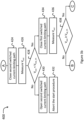
- Figures 3a , 3b and 3c illustrate a sequence 400 including operations of a diagnostic method for the electric system 1.
- the sequence 400 comprises a plurality of operations, some of which may be executed in variable order, some of the operations possibly being executed concurrently, some of the operations being optional.
- the operations of the sequence 400 are controlled by the MCM 200.
- the sequence 400 will be described in the following paragraphs considering an example in which a first pre-charge test of the capacitor 24 is executed by closing the switch 160 of the current-limiting path 150, a second pre-charge test of the capacitor 24 being then executed by closing the switch 180 of the current-limiting path 170.
- the sequence 400 may also be executed in the opposite order.
- the sequence 400 begins at operation 402, shown on Figure 3a , when a command for a start procedure is received.
- the output voltage V out of the contactor module 100 is measured at operation 404.
- both non-current limiting paths 125 and 130 are closed to allow delivery of power from the battery 10 to the power stage 20, by closing both power contactors 135 and 140 at operation 408, and the electric system 1 is placed in operation at operation 410.
- the sequence 400 continues at operation 412 where the current-limiting path 150 is closed by closing the switch 160.
- the output voltage V out of the contactor module 100 is measured at operation 414.
- operation 416 if the output voltage V out meets or exceeds the low voltage threshold V low_th , either the power contactor 140 of the switched non-current-limiting path 130 or the switch 180 of the current-limiting path 170 is determined to be closed when it should normally be open.
- the sequence 400 continues at operation 418 in which the first current-limiting path 150 that was closed at operation 412 is opened.
- operation 416 may comprise evaluating a rate of increase of the output voltage V out .
- the power contactor 140 is determined to be closed. If the rate of increase of the output voltage is consistent with the value of the capacitor 24 in relation with a series combination of the resistors 155 and 175, the switch 180 is determined to be closed. In any case, after operation 418, the start procedure is aborted at operation 420.
- the current-limiting path 150 that was closed at operation 412 is opened at operation 422 and, continuing on Figure 3b , the current-limiting path 170 is closed at operation 424.
- the output voltage V out of the contactor module 100 is measured again at operation 426.
- the sequence 400 continues at operation 430 in which the current-limiting path 170 that was closed at operation 424 is opened.
- operation 426 may comprise evaluating a rate of increase of the output voltage V out . To this end, if the rate of increase of the output voltage is consistent with the value of the capacitor 24 in relation with the resistance of the resistor 175, the power contactor 135 is determined to be closed. If the rate of increase of the output voltage is consistent with the value of the capacitor 24 in relation with a series combination of the resistors 155 and 175, the switch 160 is determined to be closed. In any case, after operation 430, and the start procedure is aborted at operation 432.
- the first current-limiting path 150 or 170 is closed again at operation 434.
- the second current-limiting path 150 or 170 that was closed at operation 424 is still closed, so current may flow between the battery 10 and the power stage 20 via the two current-limiting paths 150 and 170 to pre-charge the capacitor 24.
- the output voltage V out is measured once more at operation 436.
- the measurements of the output voltage V out at operations 404, 414, 426 and/or 432 may have been incorrect, for example due to a failure of the voltage sensor 210.
- both current-limiting paths 150 and 170 are opened at operation 440 and the start procedure is aborted at operation 442.
- both non-current limiting paths 125 and 130 are closed at operation 444, by closing both power contactors 135 and 140, to allow current to flow without restriction between the battery 10 and the power stage 20.
- Both non-current limiting paths 150 and 170 are opened at operation 446, for example to avoid continued energizing of the coils 220 and 230 by the MCM 200.
- the electric system 1 is then operated at operation 448.
- a shutdown command may be received at operation 450.
- both non-current-limiting paths are opened at operation 452 to stop delivery of power from the battery 10 to the power stage 20 by opening both contactors 135, 140.
- Operations of the sequences 300 and 400 that are executed by the MCM 200 may be configured to be processed by one or more processors, the one or more processors being coupled to a memory.
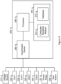
- Figure 4 is a block diagram of MCM 200 according to an embodiment.
- the MCM 200 of Figure 4 comprises a processor or a plurality of cooperating processors (represented as a single processor 260 for simplicity), a memory device or a plurality of memory devices (represented as a single memory device 270 for simplicity), an input/output device or a plurality of input/output devices (represented as an input/output device 280 for simplicity). Separate input and output devices may be present instead of the input/output device 280.
- the processor 260 is operatively connected to the memory device 270 and to the input/output device 280.
- the input/output device 280 receives a command to start the electric system 1 from a start button 290 (or from a start key or a similar device) and reports receipt of this command to the processor 260.
- the input/output device 280 also receives measurements of the output voltage of the contactor module 100 from the voltage sensor 210 and reports these measurements to the processor 260 that, in turn, controls operation of the contactor module 100.
- This control of the contactor module 100 is effected when the processor 260 causes the input/output device 280 to energize and de-energize the coils 220, 230, 240 and 250 as appropriate to close and open the switches 160 and 180 and of the power contactors 135 and 140.
- the input/output device 200 may comprise amplifier/buffers (not show) that provide sufficient current at appropriate voltages for energizing the coils 220, 230, 240 and 250.
- the processor 260 may also communicate with the power stage 20, via the input/output device 280, providing control instructions and receiving feedback signals for operating the electric system 1, for operating the vehicle.
- the memory device 270 has a database 272 for storing data which may include, for example, the above-mentioned low voltage threshold, operating voltage threshold, maximum current threshold, time range for reaching the operating voltage threshold, the early restart voltage threshold, and the like, that are used by the processor 260.
- the memory device 270 has a non-transitory computer-readable medium 274 for storing code instructions that are executable by the processor 260 to perform the operations of the sequences 300 and 400.
- the processor 260 may execute the code instructions stored in the non-transitory computer-readable medium 274 for:
- processor 260 may execute the code instructions stored in the non-transitory computer-readable medium 274 for:
- the processor 260 may further execute the code instructions stored in the non-transitory computer-readable medium 274 for receiving, via the input/output device 280, a shutdown command from the start button 290 and for opening any one of the first and second non-current-limiting paths 125 and 130 and of the current-limiting paths 150 and 170 that may be closed at a time when the shutdown command is received.
Landscapes
- Engineering & Computer Science (AREA)
- Power Engineering (AREA)
- Life Sciences & Earth Sciences (AREA)
- Sustainable Development (AREA)
- Sustainable Energy (AREA)
- Transportation (AREA)
- Mechanical Engineering (AREA)
- Electric Propulsion And Braking For Vehicles (AREA)
Claims (15)
- Système de commande de distribution de puissance (1) configuré pour distribuer sélectivement de la puissance depuis une batterie (10) à un étage de puissance (20) d'un véhicule, le système de commande de distribution de puissance comprenant :un module contacteur (100), comprenant :un premier chemin commuté sans limitation de courant (125) pouvant être connecté entre une première polarité (12) de la batterie et une première polarité (+) de l'étage de puissance du véhicule,un premier chemin commuté de limitation de courant (150) monté en parallèle avec le premier chemin commuté sans limitation de courant,un second chemin commuté sans limitation de courant (130) pouvant être connecté entre une seconde polarité (14) de la batterie et une seconde polarité (-) de l'étage de puissance du véhicule,un second chemin commuté de limitation de courant (170) monté en parallèle avec le second chemin commuté sans limitation de courant,un capteur de tension (210) configuré pour mesurer une tension de sortie (Vout) du module contacteur entre la première et la second polarité de l'étage de puissance du véhicule ; etun module de commande de moteur (200) connecté de manière fonctionnelle aux premier et second chemins commutés sans limitation de courant, aux premier et second chemins commutés de limitation de courant, et au capteur de tension, le module de commande de moteur étant configuré pour :a) initier une procédure de démarrage en réponse à la réception d'un ordre (402) pour la procédure de démarrage,b) après a), pendant la procédure de démarrage, fermer (412) sélectivement le premier chemin commuté de limitation de courant,c) après b), pendant la procédure de démarrage, en réponse à une amplitude de la tension de sortie (Vout) étant inférieure à un premier seuil de tension (Vlow_th), ouvrir (422) le premier chemin commuté de limitation de courant et fermer (424) le second chemin commuté de limitation de courant,d) après c), pendant la procédure de démarrage, en réponse à l'amplitude de la tension de sortie étant inférieure au premier seuil de tension, fermer (434) le premier chemin commuté de limitation de courant,e) après d), pendant la procédure de démarrage, en réponse à l'amplitude de la tension de sortie augmentant pour atteindre ou dépasser un second seuil de tension (Vop_th) supérieur au premier seuil de tension, fermant (444) les premier et second chemins commutés sans limitation de courant.
- Système selon la revendication 1, dans lequel le module contacteur (100) comprend en outre :une première entrée (105) configurée pour être connectée électriquement à la première polarité de la batterie ;une seconde entrée (110) configurée pour être connectée électriquement à la seconde polarité de la batterie ;une première sortie (115) configurée pour être connectée électriquement à la première polarité de l'étage de puissance du véhicule ; etune seconde sortie (120) configurée pour être connectée électriquement à la seconde polarité de l'étage de puissance du véhicule ;dans lequel :le premier chemin commuté sans limitation de courant et le premier chemin commuté de limitation de courant s'étendent entre la première entrée et la première sortie du module contacteur,le second chemin commuté sans limitation de courant et le second chemin commuté de limitation de courant s'étendent entre la seconde entrée et la seconde sortie du module contacteur, etle capteur de tension est configuré pour mesurer la tension de sortie du module contacteur entre les première et seconde sorties du module contacteur.
- Système selon la revendication 1, dans lequel le module de commande de moteur est en outre configuré pour :abandonner (420, 432) la procédure de démarrage à l'opération c) ou d) en réponse à l'amplitude de la tension de sortie atteignant ou dépassant le premier seuil de tension, etabandonner (442) la procédure de démarrage à l'opération e) en réponse à l'amplitude de la tension de sortie n'atteignant pas ou ne dépassant pas le second seuil de tension.
- Système selon la revendication 1, dans lequel le module de commande de moteur est en outre configuré pour ouvrir chacun du premier chemin commuté de limitation de courant, du second chemin commuté de limitation de courant, du premier chemin commuté sans limitation de courant et du second chemin commuté sans limitation de courant avant de recevoir l'ordre pour la procédure de démarrage.
- Système selon la revendication 1, comprenant en outre :un condensateur (24) connecté aux première et seconde polarités de l'étage de puissance du véhicule ;dans lequel :chacun du premier chemin commuté de limitation de courant, du second chemin commuté de limitation de courant, du premier chemin commuté sans limitation de courant et du second chemin commuté sans limitation de courant est normalement ouvert ;le premier chemin commuté de limitation de courant est un premier circuit de précharge pour le condensateur ;le second chemin commuté de limitation de courant est un second circuit de précharge pour le condensateur ;le premier chemin commuté de limitation de courant comprend un premier commutateur (160) connecté en série avec une première résistance (155) ;le second chemin commuté de limitation de courant comprend un second commutateur (180) connecté en série avec une seconde résistance (175) ;les résistances des première et seconde résistances sont sélectionnées en fonction d'une capacité du condensateur de sorte qu'un courant circulant entre la batterie et le condensateur en fonctionnement d) soit inférieur ou égal à un seuil de courant maximum ; et
le module de commande de moteur est en outre configuré pour :entre les opérations b) et c), déterminer que le second commutateur est fermé si la tension de sortie augmente à un rythme correspondant à une relation entre la capacité du condensateur et une somme des résistances des première et seconde résistances ;entre les opérations b) et c), déterminer que le second chemin commuté sans limitation de courant est fermé si la tension de sortie augmente à un rythme correspondant à une relation entre la capacité du condensateur et la résistance de la première résistance ;entre les opérations c) et d), détecter que le premier commutateur est fermé si la tension de sortie augmente au rythme correspondant à une relation entre la capacité du condensateur et la somme des résistances des première et seconde résistances ; etentre les opérations c) et d), détecter que le premier chemin commuté sans limitation de courant est fermé si la tension de sortie augmente à un rythme correspondant à une relation entre la capacité du condensateur et la résistance de la seconde résistance. - Système selon la revendication 1, dans lequel le module de commande de moteur est en outre configuré pour ouvrir les premier et second chemins commutés de limitation de courant après avoir fermé les premier et second chemins commutés sans limitation de courant.
- Système selon la revendication 1, dans lequel le module de commande de moteur est en outre configuré pour :vérifier la tension de sortie après l'opération a) et avant l'opération b) ;exécuter l'opération b) en réponse à la tension de sortie mesurée après l'opération a) étant inférieure à un seuil de tension de redémarrage anticipé ; etfermer les premier et second chemins commutés sans limitation de courant en réponse à la tension de sortie mesurée après l'opération a) étant égale ou supérieure au seuil de tension de redémarrage anticipé.
- Système selon la revendication 1, dans lequel le module de commande de moteur est en outre configuré pour :recevoir un ordre d'arrêt (450) ; etouvrir (452) l'un quelconque du premier chemin commuté sans limitation de courant, du second chemin commuté sans limitation de courant, du premier chemin commuté de limitation de courant et du second chemin commuté de limitation de courant qui est fermé à un temps de réception de l'ordre d'arrêt.
- Procédé de diagnostic pour un système électrique comprenant un étage de puissance d'un véhicule, le procédé comprenant :a) l'initiation d'une procédure de démarrage en réponse à la réception, au niveau du système électrique, d'un ordre pour la procédure de démarrage ;b) après a), pendant la procédure de démarrage, fermer sélectivement un premier chemin commuté de limitation de courant connectant une première polarité d'une batterie à une première polarité d'un étage de puissance du véhicule du système électrique ;c) après b), pendant la procédure de démarrage, si une amplitude d'une tension de sortie entre la première polarité de l'étage de puissance du véhicule et une seconde polarité de l'étage de puissance du véhicule est inférieure à un premier seuil de tension, ouvrir le premier chemin commuté de limitation de courant et fermer un second chemin commuté de limitation de courant connectant une seconde polarité de la batterie à la seconde polarité de l'étage de puissance du véhicule ;d) après c), pendant la procédure de démarrage, si l'amplitude de la tension de sortie est inférieure au premier seuil de tension, fermer le premier chemin commuté de limitation de courant ;e) après d), pendant la procédure de démarrage, si l'amplitude de la tension de sortie augmente pour atteindre ou dépasser un second seuil de tension supérieur au premier seuil de tension, fermer un premier chemin sans limitation de courant parallèle au premier chemin de limitation de courant et fermer un second chemin commuté sans limitation de courant parallèle au premier chemin de limitation de courant.
- Procédé selon la revendication 9, comprenant en outre :l'abandon de la procédure de démarrage lors de l'opération c) ou d) en réponse à l'amplitude de la tension de sortie atteignant ou dépassant le premier seuil de tension, etl'abandon de la procédure de démarrage lors de l'opération e) en réponse à l'amplitude de la tension de sortie n'atteignant pas ou ne dépassant pas le second seuil de tension.
- Procédé selon la revendication 16, dans lequel :chacun du premier chemin commuté de limitation de courant, du second chemin commuté de limitation de courant, du premier chemin commuté sans limitation de courant et du second chemin commuté sans limitation de courant est normalement ouvert ;un condensateur est connecté aux première et seconde polarités de l'étage de puissance du véhicule ;la fermeture des premier et second chemins commutés de limitation de courant précharge le condensateur ;la fermeture du premier chemin commuté de limitation de courant comprend la fermeture d'un premier commutateur connecté en série avec une première résistance ;la fermeture du second chemin commuté de limitation de courant comprend la fermeture d'un second commutateur connecté en série avec une seconde résistance ; etles résistances des première et seconde résistances sont sélectionnées en fonction d'une capacité du condensateur de sorte qu'un courant circulant entre la batterie et le condensateur en fonctionnement d) est inférieur ou égal à un seuil de courant maximum ;
le procédé comprenant en outre :entre les opérations b) et c), déterminer que le second commutateur est fermé si la tension de sortie augmente à un rythme correspondant à une relation entre la capacité du condensateur et une somme des résistances des première et seconde résistances ;entre les opérations b) et c), déterminer que le second chemin commuté sans limitation de courant est fermé si la tension de sortie augmente à un rythme correspondant à une relation entre la capacité du condensateur et la résistance de la première résistance ;entre les opérations c) et d), détecter que le premier commutateur est fermé si la tension de sortie augmente au rythme correspondant à une relation entre la capacité du condensateur et la somme des résistances des première et seconde résistances ; etentre les opérations c) et d), détecter que le premier chemin commuté sans limitation de courant est fermé si la tension de sortie augmente à un rythme correspondant à une relation entre la capacité du condensateur et la résistance de la seconde résistance. - Procédé selon la revendication 9, comprenant en outre l'ouverture de chacun du premier chemin commuté de limitation de courant, du second chemin commuté de limitation de courant, du premier chemin commuté sans limitation de courant et du second chemin commuté sans limitation de courant avant de recevoir l'ordre pour la procédure de démarrage.
- Procédé selon la revendication 9, comprenant en outre l'ouverture des premier et second chemins commutés de limitation de courant après la fermeture des premier et second chemins commutés sans limitation de courant.
- Procédé selon la revendication 9, comprenant en outre :vérifier la tension de sortie après l'opération a) et avant l'opération b) ;exécuter l'opération b) en réponse à la tension de sortie mesurée après l'opération a) étant inférieure à un seuil de tension de redémarrage anticipé ; etfermer les premier et second chemins commutés sans limitation de courant en réponse à la tension de sortie mesurée après l'opération a) étant égale ou supérieure au seuil de tension de redémarrage anticipé.
- Procédé selon la revendication 9, comprenant en outre :la réception d'un ordre d'arrêt au niveau du système électrique ; etl'ouverture de l'un quelconque du premier chemin commuté sans limitation de courant, du second chemin commuté sans limitation de courant, du premier chemin commuté de limitation de courant et du second chemin commuté de limitation de courant qui est fermé à un temps de réception de l'ordre d'arrêt.
Applications Claiming Priority (2)
| Application Number | Priority Date | Filing Date | Title |
|---|---|---|---|
| US202163143466P | 2021-01-29 | 2021-01-29 | |
| PCT/EP2022/052074 WO2022162159A1 (fr) | 2021-01-29 | 2022-01-28 | Système de commande de distribution de puissance pour véhicule électrique et procédé de diagnostic associé |
Publications (3)
| Publication Number | Publication Date |
|---|---|
| EP4267422A1 EP4267422A1 (fr) | 2023-11-01 |
| EP4267422C0 EP4267422C0 (fr) | 2024-06-19 |
| EP4267422B1 true EP4267422B1 (fr) | 2024-06-19 |
Family
ID=80222440
Family Applications (1)
| Application Number | Title | Priority Date | Filing Date |
|---|---|---|---|
| EP22702943.6A Active EP4267422B1 (fr) | 2021-01-29 | 2022-01-28 | Système de commande de distribution de puissance pour véhicule électrique et procédé de diagnostic associé |
Country Status (4)
| Country | Link |
|---|---|
| US (1) | US20240083253A1 (fr) |
| EP (1) | EP4267422B1 (fr) |
| CA (1) | CA3206689A1 (fr) |
| WO (1) | WO2022162159A1 (fr) |
Families Citing this family (3)
| Publication number | Priority date | Publication date | Assignee | Title |
|---|---|---|---|---|
| US12485981B2 (en) | 2021-03-24 | 2025-12-02 | Polaris Industries Inc. | Electric recreational vehicle |
| JP7652101B2 (ja) * | 2022-02-08 | 2025-03-27 | トヨタ自動車株式会社 | 充放電装置、車両、および、充放電装置の制御方法 |
| US20240425004A1 (en) * | 2023-06-23 | 2024-12-26 | Mtd Products Inc | Power distribution module |
Family Cites Families (6)
| Publication number | Priority date | Publication date | Assignee | Title |
|---|---|---|---|---|
| EP1032964A2 (fr) * | 1997-11-17 | 2000-09-06 | Lifestyle Technologies | Systeme d'alimentation polyvalent |
| US6295215B1 (en) * | 2000-04-06 | 2001-09-25 | Powerware Corporation | AC power supply apparatus with economy mode and methods of operation thereof |
| JP4539431B2 (ja) * | 2005-05-11 | 2010-09-08 | トヨタ自動車株式会社 | 電源制御装置 |
| EP3943335B1 (fr) * | 2016-11-30 | 2024-05-15 | Bombardier Recreational Products Inc. | Procédé d'excitation d'un système électrique |
| US10476262B2 (en) * | 2017-03-24 | 2019-11-12 | Ford Global Technologies, Llc | Dual-bus battery precharge circuit |
| JP7177005B2 (ja) * | 2019-06-10 | 2022-11-22 | 本田技研工業株式会社 | 電源システム及びその制御方法 |
-
2022
- 2022-01-28 WO PCT/EP2022/052074 patent/WO2022162159A1/fr not_active Ceased
- 2022-01-28 EP EP22702943.6A patent/EP4267422B1/fr active Active
- 2022-01-28 CA CA3206689A patent/CA3206689A1/fr active Pending
- 2022-01-28 US US18/263,165 patent/US20240083253A1/en active Pending
Also Published As
| Publication number | Publication date |
|---|---|
| EP4267422A1 (fr) | 2023-11-01 |
| US20240083253A1 (en) | 2024-03-14 |
| WO2022162159A1 (fr) | 2022-08-04 |
| EP4267422C0 (fr) | 2024-06-19 |
| CA3206689A1 (fr) | 2022-08-04 |
Similar Documents
| Publication | Publication Date | Title |
|---|---|---|
| EP4267422B1 (fr) | Système de commande de distribution de puissance pour véhicule électrique et procédé de diagnostic associé | |
| CN109975695B (zh) | 电系统和诊断电系统中的功率继电器的功能能力的方法 | |
| CN102844670B (zh) | 用于机动车的高压系统和用于诊断机动车高压系统的方法 | |
| US8866441B2 (en) | Interlock mechanism for a multiple battery pack | |
| CN102729828B (zh) | 电源装置及其控制方法 | |
| US20130278273A1 (en) | Method and device for detecting short circuit | |
| JP4156668B2 (ja) | 電気アクチュエータ駆動段を試験する方法および回路 | |
| CN101427335A (zh) | 电源控制装置及继电器的异常检测方法 | |
| JP2020137334A (ja) | プリチャージ制御装置 | |
| KR102663546B1 (ko) | 차량의 고전압 직류 링크 커패시터의 프리차지 방법 및 시스템 | |
| KR101795319B1 (ko) | 차량의 고전압 시스템의 퓨즈 단선 검출 시스템 및 방법 | |
| WO2015008509A1 (fr) | Dispositif de commande de source d'alimentation et procédé de détection d'anomalie de relais | |
| JP2020099112A (ja) | プリチャージ制御装置 | |
| JP5994652B2 (ja) | 車両用電源制御装置 | |
| JP4604485B2 (ja) | 電源系統の異常検知装置 | |
| JP4529851B2 (ja) | 電源回路の異常検知装置 | |
| WO2013150825A1 (fr) | Alimentation électrique et procédé de détection d'anomalie d'alimentation électrique | |
| JP2017093008A (ja) | コンタクタ故障判定装置およびコンタクタ故障判定方法 | |
| JP2006238509A (ja) | 電動車輌の制御装置、電動車輌の制御方法、プログラム及びコンピュータ可読記録媒体 | |
| JP7391482B2 (ja) | 地絡検出装置 | |
| US20260094779A1 (en) | In-vehicle power supply device | |
| JP6385530B1 (ja) | スイッチ診断装置及びスイッチ診断方法 | |
| CN120359682A (zh) | 电变流器、电驱动及充电系统以及用于检查电变流器中开关元件的方法 | |
| US20250070588A1 (en) | Partial pre-charge of the high voltage system | |
| JP7799936B2 (ja) | 車載用電源装置 |
Legal Events
| Date | Code | Title | Description |
|---|---|---|---|
| STAA | Information on the status of an ep patent application or granted ep patent |
Free format text: STATUS: UNKNOWN |
|
| STAA | Information on the status of an ep patent application or granted ep patent |
Free format text: STATUS: THE INTERNATIONAL PUBLICATION HAS BEEN MADE |
|
| PUAI | Public reference made under article 153(3) epc to a published international application that has entered the european phase |
Free format text: ORIGINAL CODE: 0009012 |
|
| STAA | Information on the status of an ep patent application or granted ep patent |
Free format text: STATUS: REQUEST FOR EXAMINATION WAS MADE |
|
| 17P | Request for examination filed |
Effective date: 20230728 |
|
| AK | Designated contracting states |
Kind code of ref document: A1 Designated state(s): AL AT BE BG CH CY CZ DE DK EE ES FI FR GB GR HR HU IE IS IT LI LT LU LV MC MK MT NL NO PL PT RO RS SE SI SK SM TR |
|
| GRAP | Despatch of communication of intention to grant a patent |
Free format text: ORIGINAL CODE: EPIDOSNIGR1 |
|
| STAA | Information on the status of an ep patent application or granted ep patent |
Free format text: STATUS: GRANT OF PATENT IS INTENDED |
|
| DAV | Request for validation of the european patent (deleted) | ||
| DAX | Request for extension of the european patent (deleted) | ||
| INTG | Intention to grant announced |
Effective date: 20240116 |
|
| GRAS | Grant fee paid |
Free format text: ORIGINAL CODE: EPIDOSNIGR3 |
|
| GRAA | (expected) grant |
Free format text: ORIGINAL CODE: 0009210 |
|
| STAA | Information on the status of an ep patent application or granted ep patent |
Free format text: STATUS: THE PATENT HAS BEEN GRANTED |
|
| AK | Designated contracting states |
Kind code of ref document: B1 Designated state(s): AL AT BE BG CH CY CZ DE DK EE ES FI FR GB GR HR HU IE IS IT LI LT LU LV MC MK MT NL NO PL PT RO RS SE SI SK SM TR |
|
| REG | Reference to a national code |
Ref country code: GB Ref legal event code: FG4D |
|
| RIN1 | Information on inventor provided before grant (corrected) |
Inventor name: HOESSLE, FLORIAN Inventor name: WOLFSEGGER, SIMON Inventor name: WESENAUER, SEVERIN |
|
| REG | Reference to a national code |
Ref country code: CH Ref legal event code: EP |
|
| REG | Reference to a national code |
Ref country code: DE Ref legal event code: R096 Ref document number: 602022004049 Country of ref document: DE |
|
| U01 | Request for unitary effect filed |
Effective date: 20240717 |
|
| U07 | Unitary effect registered |
Designated state(s): AT BE BG DE DK EE FI FR IT LT LU LV MT NL PT SE SI Effective date: 20240725 |
|
| PG25 | Lapsed in a contracting state [announced via postgrant information from national office to epo] |
Ref country code: HR Free format text: LAPSE BECAUSE OF FAILURE TO SUBMIT A TRANSLATION OF THE DESCRIPTION OR TO PAY THE FEE WITHIN THE PRESCRIBED TIME-LIMIT Effective date: 20240619 |
|
| PG25 | Lapsed in a contracting state [announced via postgrant information from national office to epo] |
Ref country code: GR Free format text: LAPSE BECAUSE OF FAILURE TO SUBMIT A TRANSLATION OF THE DESCRIPTION OR TO PAY THE FEE WITHIN THE PRESCRIBED TIME-LIMIT Effective date: 20240920 |
|
| PG25 | Lapsed in a contracting state [announced via postgrant information from national office to epo] |
Ref country code: NO Free format text: LAPSE BECAUSE OF FAILURE TO SUBMIT A TRANSLATION OF THE DESCRIPTION OR TO PAY THE FEE WITHIN THE PRESCRIBED TIME-LIMIT Effective date: 20240919 Ref country code: HR Free format text: LAPSE BECAUSE OF FAILURE TO SUBMIT A TRANSLATION OF THE DESCRIPTION OR TO PAY THE FEE WITHIN THE PRESCRIBED TIME-LIMIT Effective date: 20240619 Ref country code: GR Free format text: LAPSE BECAUSE OF FAILURE TO SUBMIT A TRANSLATION OF THE DESCRIPTION OR TO PAY THE FEE WITHIN THE PRESCRIBED TIME-LIMIT Effective date: 20240920 Ref country code: RS Free format text: LAPSE BECAUSE OF FAILURE TO SUBMIT A TRANSLATION OF THE DESCRIPTION OR TO PAY THE FEE WITHIN THE PRESCRIBED TIME-LIMIT Effective date: 20240919 |
|
| PG25 | Lapsed in a contracting state [announced via postgrant information from national office to epo] |
Ref country code: PL Free format text: LAPSE BECAUSE OF FAILURE TO SUBMIT A TRANSLATION OF THE DESCRIPTION OR TO PAY THE FEE WITHIN THE PRESCRIBED TIME-LIMIT Effective date: 20240619 |
|
| PG25 | Lapsed in a contracting state [announced via postgrant information from national office to epo] |
Ref country code: IS Free format text: LAPSE BECAUSE OF FAILURE TO SUBMIT A TRANSLATION OF THE DESCRIPTION OR TO PAY THE FEE WITHIN THE PRESCRIBED TIME-LIMIT Effective date: 20241019 |
|
| PG25 | Lapsed in a contracting state [announced via postgrant information from national office to epo] |
Ref country code: CZ Free format text: LAPSE BECAUSE OF FAILURE TO SUBMIT A TRANSLATION OF THE DESCRIPTION OR TO PAY THE FEE WITHIN THE PRESCRIBED TIME-LIMIT Effective date: 20240619 |
|
| PG25 | Lapsed in a contracting state [announced via postgrant information from national office to epo] |
Ref country code: RO Free format text: LAPSE BECAUSE OF FAILURE TO SUBMIT A TRANSLATION OF THE DESCRIPTION OR TO PAY THE FEE WITHIN THE PRESCRIBED TIME-LIMIT Effective date: 20240619 Ref country code: SK Free format text: LAPSE BECAUSE OF FAILURE TO SUBMIT A TRANSLATION OF THE DESCRIPTION OR TO PAY THE FEE WITHIN THE PRESCRIBED TIME-LIMIT Effective date: 20240619 |
|
| PG25 | Lapsed in a contracting state [announced via postgrant information from national office to epo] |
Ref country code: ES Free format text: LAPSE BECAUSE OF FAILURE TO SUBMIT A TRANSLATION OF THE DESCRIPTION OR TO PAY THE FEE WITHIN THE PRESCRIBED TIME-LIMIT Effective date: 20240619 Ref country code: SM Free format text: LAPSE BECAUSE OF FAILURE TO SUBMIT A TRANSLATION OF THE DESCRIPTION OR TO PAY THE FEE WITHIN THE PRESCRIBED TIME-LIMIT Effective date: 20240619 |
|
| PG25 | Lapsed in a contracting state [announced via postgrant information from national office to epo] |
Ref country code: SM Free format text: LAPSE BECAUSE OF FAILURE TO SUBMIT A TRANSLATION OF THE DESCRIPTION OR TO PAY THE FEE WITHIN THE PRESCRIBED TIME-LIMIT Effective date: 20240619 Ref country code: SK Free format text: LAPSE BECAUSE OF FAILURE TO SUBMIT A TRANSLATION OF THE DESCRIPTION OR TO PAY THE FEE WITHIN THE PRESCRIBED TIME-LIMIT Effective date: 20240619 Ref country code: RO Free format text: LAPSE BECAUSE OF FAILURE TO SUBMIT A TRANSLATION OF THE DESCRIPTION OR TO PAY THE FEE WITHIN THE PRESCRIBED TIME-LIMIT Effective date: 20240619 Ref country code: PL Free format text: LAPSE BECAUSE OF FAILURE TO SUBMIT A TRANSLATION OF THE DESCRIPTION OR TO PAY THE FEE WITHIN THE PRESCRIBED TIME-LIMIT Effective date: 20240619 Ref country code: IS Free format text: LAPSE BECAUSE OF FAILURE TO SUBMIT A TRANSLATION OF THE DESCRIPTION OR TO PAY THE FEE WITHIN THE PRESCRIBED TIME-LIMIT Effective date: 20241019 Ref country code: ES Free format text: LAPSE BECAUSE OF FAILURE TO SUBMIT A TRANSLATION OF THE DESCRIPTION OR TO PAY THE FEE WITHIN THE PRESCRIBED TIME-LIMIT Effective date: 20240619 Ref country code: CZ Free format text: LAPSE BECAUSE OF FAILURE TO SUBMIT A TRANSLATION OF THE DESCRIPTION OR TO PAY THE FEE WITHIN THE PRESCRIBED TIME-LIMIT Effective date: 20240619 |
|
| U20 | Renewal fee for the european patent with unitary effect paid |
Year of fee payment: 4 Effective date: 20250127 |
|
| PLBE | No opposition filed within time limit |
Free format text: ORIGINAL CODE: 0009261 |
|
| STAA | Information on the status of an ep patent application or granted ep patent |
Free format text: STATUS: NO OPPOSITION FILED WITHIN TIME LIMIT |
|
| 26N | No opposition filed |
Effective date: 20250320 |
|
| REG | Reference to a national code |
Ref country code: CH Ref legal event code: PL |
|
| PG25 | Lapsed in a contracting state [announced via postgrant information from national office to epo] |
Ref country code: MC Free format text: LAPSE BECAUSE OF FAILURE TO SUBMIT A TRANSLATION OF THE DESCRIPTION OR TO PAY THE FEE WITHIN THE PRESCRIBED TIME-LIMIT Effective date: 20240619 |
|
| PG25 | Lapsed in a contracting state [announced via postgrant information from national office to epo] |
Ref country code: CH Free format text: LAPSE BECAUSE OF NON-PAYMENT OF DUE FEES Effective date: 20250131 |
|
| PG25 | Lapsed in a contracting state [announced via postgrant information from national office to epo] |
Ref country code: IE Free format text: LAPSE BECAUSE OF NON-PAYMENT OF DUE FEES Effective date: 20250128 |
|
| U20 | Renewal fee for the european patent with unitary effect paid |
Year of fee payment: 5 Effective date: 20260126 |