EP4267789B1 - Wäschetrocknungsgerät mit betriebsmodus zur umgebungsluftentfeuchtung - Google Patents
Wäschetrocknungsgerät mit betriebsmodus zur umgebungsluftentfeuchtung Download PDFInfo
- Publication number
- EP4267789B1 EP4267789B1 EP20839116.9A EP20839116A EP4267789B1 EP 4267789 B1 EP4267789 B1 EP 4267789B1 EP 20839116 A EP20839116 A EP 20839116A EP 4267789 B1 EP4267789 B1 EP 4267789B1
- Authority
- EP
- European Patent Office
- Prior art keywords
- air
- filter
- laundry
- seat
- drying
- Prior art date
- Legal status (The legal status is an assumption and is not a legal conclusion. Google has not performed a legal analysis and makes no representation as to the accuracy of the status listed.)
- Active
Links
Images





Classifications
-
- D—TEXTILES; PAPER
- D06—TREATMENT OF TEXTILES OR THE LIKE; LAUNDERING; FLEXIBLE MATERIALS NOT OTHERWISE PROVIDED FOR
- D06F—LAUNDERING, DRYING, IRONING, PRESSING OR FOLDING TEXTILE ARTICLES
- D06F58/00—Domestic laundry dryers
- D06F58/20—General details of domestic laundry dryers
-
- D—TEXTILES; PAPER
- D06—TREATMENT OF TEXTILES OR THE LIKE; LAUNDERING; FLEXIBLE MATERIALS NOT OTHERWISE PROVIDED FOR
- D06F—LAUNDERING, DRYING, IRONING, PRESSING OR FOLDING TEXTILE ARTICLES
- D06F58/00—Domestic laundry dryers
- D06F58/20—General details of domestic laundry dryers
- D06F58/22—Lint collecting arrangements
Definitions
- the solution according to embodiments of the present invention generally relates to household and/or professional laundry treating appliances configured for performing drying operations (e.g. , laundry washing/drying machines and drying machines, hereinafter both referred to as “laundry drying appliances” or simply “laundry appliances” for the sake of conciseness).
- laundry drying appliances e.g. , laundry washing/drying machines and drying machines, hereinafter both referred to as “laundry drying appliances” or simply “laundry appliances” for the sake of conciseness).
- Laundry appliances (such as laundry washing/drying machines and drying machines) configured to dry laundry generally comprise a laundry chamber configured for housing a laundry load (including articles such as clothes and other textiles) and for causing drying air circulating therethrough to remove moisture from the laundry load.
- a laundry chamber configured for housing a laundry load (including articles such as clothes and other textiles) and for causing drying air circulating therethrough to remove moisture from the laundry load.
- DE3710615 discloses a washing and drying machine with a drawer receptacle provided in the upper housing region.
- a washing-agent flush-in tray is inserted into the drawer receptacle, and when it is to operate as a laundry drier, the washing-agent flush-in tray is taken out of the drawer receptacle and replaced by a lint separator.
- EP2843100 discloses a laundry washing/drying appliance comprising a laundry chamber for containing laundry to be washed/dried, an air circulation system adapted to cyclically circulate drying air through the laundry chamber during a drying process, and a washing products dispensing conduit adapted to dispense washing products into the laundry chamber during a washing process. An amount of drying air within the laundry chamber is allowed to leave the air circulation system during the drying process.
- a class of laundry appliances provides to dry the laundry load inside the laundry chamber by circulating drying air through the laundry chamber in a substantially closed air circuit.
- This air circuit provides that (damp) air leaving the laundry chamber is passed through a demoisturizing unit, where it is demoisturized, and then through a heating unit, where it is heated up to form dry and hot air that is then fed again inside the laundry chamber for evaporating moisture from the laundry load.
- Laundry appliances are known whose operation is configured to be switched between a standard "laundry drying mode” directed to dry laundry inside the laundry chamber and an "ambient air dehumidification mode” directed to remove humidity from the room wherein the laundry drying appliance is located.
- EP2684994 discloses a dryer having a dryer housing comprising a housing front face for supplying objects to a drying chamber, and a processing air channel for guiding processing air and located inside the housing.
- An exhaust air duct guides exhaust air from the chamber.
- the face comprises a recess region, where an adapter and another adapter are insertable into the recess region.
- a normal drying process of the objects in the chamber is carried out during utilization of the former adapter.
- a space containing the dryer is dehumidified during utilization of the latter adapter.
- the Applicant has found that the known laundry appliances capable of selectively drying laundry inside the laundry chamber or removing humidity from the room wherein the laundry drying appliance is located are affected by drawbacks.
- EP2684994 is not efficient, because of the increased complexity due to the requirement of using two different adapters to be selectively inserted in a dedicated recess area.
- this solution is affected by the further disadvantage of forcing the user to find a place where storing either of the two adapters which is not in use.
- An aspect of the solution according to one or more embodiments of the invention relates to a laundry drying appliance.
- the laundry appliance comprises a cabinet.
- the laundry appliance further comprises a laundry chamber rotatably enclosed within the cabinet for containing laundry to be dried.
- the laundry appliance further comprises a drying air flow system for passing said air through the laundry chamber, said drying air flow system comprising an air demoisturizing unit configured to demoisturize said air.
- the laundry appliance further comprises a filter seat arranged within the drying flow system for removably receiving an air filter.
- the air filter is movable from a first position wherein it is inserted into said filter seat to filter drying air leaving the laundry chamber, to a second position wherein it is removed from said filter seat and detached from the appliance and viceversa;
- the laundry drying appliance is configured to operate in a laundry dryer mode when the air filter is in the first position, and in an ambient air dehumidification mode to dehumidify air in the ambient outside the cabinet when the air filter is said second position.
- the laundry drying appliance further comprises a movable wall system arranged within said filter seat and operable, by moving said air filter from one to the other of said first and second positions, to configure the drying air flow system such that:
- Said movable wall system is configured so that, when the air filter is in said second position, the operation of the movable wall system causes the volume of the filter seat to be split in:
- the movable wall system is advantageously adapted to accordingly configure the drying air flow system of the laundry appliance by simply inserting or removing the air filter unit from the filter seat, without having to be forced to manage different dedicated adapters.
- the proposed solution does not require the provision of a dedicated opening in the casing of the laundry appliance for accessing the drying air flow in order to change its configuration, because in the proposed solution said configuration can be easily performed by accessing the drying air flow through the filter seat.
- the movable wall system comprises first and second wall members pivotally coupled to the filter seat and configured to be rotated between:
- the movable wall system comprises first and second wall members pivotally coupled to the filter seat and configured to be rotated between:
- the filter seat comprises a seat opening provided between said ceiling portion and said floor portion to receive the air filter therein.
- the second wall member of the movable wall system comprises said air introduction opening and air exhausting opening formed thereon to partly obstructing the seat opening when the air filter is in the second position.
- said first wall member and said second wall member are configured to be rotated from the unfolded position to the folded position when said air filter element is being inserted in the filter seat through said seat opening to reach said first position.
- said first wall member forms an angle comprised between 90° and 115° with respect to the ceiling portion of the filter seat when the first wall member is in the unfolded position.
- said second wall member comprises a profiled member on a first face of the second wall member facing inside the filter seat when the second wall member is in the unfolded position.
- said profiled member is configured as a cam of a cam system comprising a follower provided as a profiled edge of the first wall member, so that the rotation of the second wall member toward the folded position causes a corresponding rotation of the first wall member toward the folded position.
- said profiled member of said second wall member has a chamfered shape protruding from said first face of the second wall member.
- said profiled member of said second wall member has a shape substantially corresponding to an oblique triangular prism.
- said second wall member comprises at least one elastic element biased in such a way that the second wall member is rotated from the folded position to the unfolded position when the filter element is being extracted from the filter seat.
- said drying air flow system comprises an air heating unit configured to heat up air demoisturized by the demoisturizing unit.
- said air demoisturizing unit comprises an evaporation unit and said air heating unit comprises a condenser unit, of a heat pump system.
- said air demoisturizing unit comprises an evaporation unit and said air heating unit comprises a condenser unit, of a heat pump system which is designed for condensing an amount of moisture ranging from 8 liters/day to 12 liters/day from an ambient at 32°C and 80% of relative humidity. Said 'day' being intended as a time of 24 hours.
- said heat pump system is designed for condensing an amount of moisture ranging from 9 liters/day to 11 liters/day from an ambient at 32°C and 80% of relative humidity. Said 'day' being intended as a time of 24 hours.
- said air demoisturizing unit comprises an air/air heat exchanger unit and said air heating unit comprises an heating resistor.
- said air demoisturizing unit comprises an air/water exchanger unit and said air heating unit comprises an heating resistor.
- said cabinet comprises sidewalls and a box-like structure acting as worktop arranged on the sidewalls so as to close the inner volume of the cabinet from above.
- said air demoisturizing unit comprises an evaporation unit and said air heating unit comprises a condenser unit, of a heat pump system and the evaporation unit and/or the condenser unit is/are arranged within a volume of a box-like structure acting as worktop arranged on cabinet sidewalls so as to close the inner volume of the cabinet from above, said box-like structure having an height ranging from 2 cm to 8 cm and a width and/or a length ranging from 45 cm to 65 cm.
- said box-like structure is formed by walls having a thickness ranging from 0,1 cm to 1 cm.
- said box-like structure comprising an air duct forming part of said drying air flow system, said filter seat being arranged within the air duct for removably receiving the air filter therein.
- said box-like structure comprises:
- Another aspect of the present invention relates to a worktop configured to form the top wall of a laundry drying appliance cabinet by being arranged on sidewalls thereof so as to close the inner volume of the cabinet from above.
- the worktop comprises:
- the worktop comprises a movable wall system arranged within said filter seat, said movable wall system being operable by moving the air filter from one to the other of said first and second positions to configure the air duct such that:
- the proposed worktop comprising the movable wall system can be easily installed in a standard laundry drying appliance by simply replacing the old worktop with the proposed one.
- a standard laundry appliance can be enriched with the possibility of operating in an ambient air dehumidification operative mode without having to modify the component housed in the cabinet.
- said air duct is further provided with an air heating unit configured to heat up air demoisturized by the demoisturizing unit.
- said upper wall comprises a removable portion located at the movable wall system for accessing said movable wall system.
- said movable wall system is at least partially coupled to said removable portion of the upper wall.
- Another aspect of the present invention relates to a method to operate a laundry drying appliance in a laundry dryer mode so as to dry laundry contained in the laundry chamber, or in an ambient air dehumidification mode to dehumidify air in the ambient outside the cabinet of the appliance.
- the method comprises:
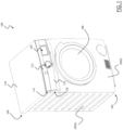
- Figure 1 is a perspective view of a laundry appliance 100 wherein concepts according to embodiments of the present invention can be applied.
- the laundry appliance 100 illustrated in Figure 1 is a laundry washing/drying machine configured to wash and dry laundry.
- the concepts of the present invention may be applied to other kinds of laundry appliances capable of drying laundry, such as in case the laundry appliance 100 is a drying machine configured only to dry laundry.
- the laundry appliance 100 comprises a cabinet 105, for example a substantially parallepiped-shaped cabinet 105, having a front wall 105(1), two side walls 105(s) (only one visible in Figure 1 ), and a bottom wall (not visible in Figure 1 ).
- a cabinet 105 for example a substantially parallepiped-shaped cabinet 105, having a front wall 105(1), two side walls 105(s) (only one visible in Figure 1 ), and a bottom wall (not visible in Figure 1 ).
- the cabinet 105 encloses an inner compartment housing a laundry chamber (not visible in Figure 1 ) for containing laundry to be treated (e.g ., dried and/or washed) and accessible through an access door 108 (shown in closed configuration).
- the laundry chamber is rotatably enclosed within the cabinet 105, so that it can rotate with respect to the latter for promoting tumbling of laundry.
- the laundry chamber is a rotatable drum.
- the laundry chamber is a rotatable drum housed in a washing tub (not visible in the figures).
- the washing tub is not provided.
- the laundry appliance 100 comprises a drying air flow system for passing air through the laundry chamber.
- the laundry appliance 100 comprises a box-like structure 109 acting as a (e.g. , ready-to-mount) worktop (hereinafter simply referred to as "worktop”) arranged on the side walls 105(s) so as to close the inner volume of the cabinet 105 from above.
- the worktop 109 may be advantageously covered by a covering panel 110 for aesthetical purposes.
- a portion of the drying air flow system for passing air through the laundry chamber is housed inside the worktop 109.
- the laundry appliance 100 comprises a filter seat 111 configured for removably receiving a removable air filter unit 112.
- the air filter unit 112 is configured in such a way that, when it is inserted in the filter seat 111, (damp) air coming from the laundry chamber is expediently filtered from fluff.
- the filter seat 111 is located at a front portion of the worktop 109.
- the laundry appliance 100 further comprises a drawer 115 for containing one or more laundry treatment agents (or, concisely, treatment agents), such as liquid and powder treatment agents including, but not limited to, washing detergents, rinsing detergents, bleaches and softeners.
- the drawer 115 is configured to slide into a drawer seat 118, preferably provided on a top part of the front wall 105(1) of the cabinet 105, between an extracted position and a retracted position (shown in Figure 1 ).
- the drawer 115 is not provided.
- the laundry appliance 100 further comprises a user interface 120, the user interface 120 being preferably provided on a top part of the front wall 105(f) of the cabinet 105.
- the laundry appliance 100 is configured to operate in two different operative modes, and particularly in:
- the operation of the laundry appliance 100 can be switched between the laundry dryer operative mode and the ambient air dehumidification operative mode based on the position of the air filter unit 112, particularly with respect to the filter seat 111.
- the laundry appliance 100 when the air filter unit 112 is in a first position wherein it is inserted into the filter seat 111, the laundry appliance 100 is configured to operate in the laundry dryer operative mode.
- the laundry appliance 100 when the air filter unit 112 is in a second position wherein it is removed from the filter seat 111 and detached from the laundry appliance 100, the laundry appliance 100 is configured to operate in the ambient air dehumidification operative mode.
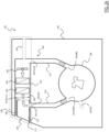
- Figure 2A conceptually shows how the drying air flow system of the laundry appliance 100 - identified with reference 204 - is configured according to an embodiment of the present invention when the laundry appliance 100 is in the laundry dryer operative mode, i.e. , when the air filter unit 112 is inserted in the filter seat 111.
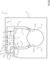
- Figure 2B conceptually shows how the drying air flow system 204 is configured according to an embodiment of the present invention when the laundry appliance 100 is in the ambient air dehumidification operative mode, i.e., when the air filter unit 112 is removed from the filter seat 111 and detached from the laundry appliance 100.
- laundry to be dried is expected to be located inside the laundry chamber - the laundry chamber being identified in Figures 2A and 2B with reference 206.
- the laundry chamber 206 is expected to be empty.
- the drying air flow system 204 is configured to circulate drying air in a substantially closed air circuit through the laundry chamber 206 (containing laundry to be dried) and the air filter unit 112.
- the air flow system 204 comprises a main air duct 210, a delivery air duct 212 and a return air duct 214.
- the delivery air duct 212 is fluidly connected to an input opening IN(206) of the laundry chamber 206 for supplying it with drying air.
- the return air duct 214 is fluidly connected to an output opening OUT(206) of the laundry chamber 206 for taking moisture-laden air (damp air) derived from the laundry drying process.
- the main air duct 210 is provided between (and connecting) the delivery air duct 212 and the return air duct 214.
- the return air duct 214 is fluidly connected to an air inlet aperture IN(210) of the main air duct 210 for introducing in the main air duct 210 damp air coming from the laundry chamber 206.
- the delivery air duct 212 is fluidly connected to an air outlet aperture OUT(210) of the main air duct 210 for receiving drying air to be provided to the laundry chamber 206.
- the main air duct 210 is comprised in the worktop 109.
- the filter seat 111 is housed in the main air duct 210.
- the filter seat 111 comprises between a filter seat ceiling portion and a filter seat floor portion a seat opening 216 configured to receive the air filter unit 112.
- the filter unit 112 closes the seat opening 216, preventing a fluid communication between the inner volume of the filter seat 111 and the ambient outside the laundry appliance 100.
- the inner volume of the filter seat 111 is in fluid communication with the ambient outside the laundry appliance 100 through the seat opening 216.
- the filter seat 111 comprises an air input IN(111) for receiving air and an air output OUT(111) for exhausting air.
- the air input IN(111) and the air output OUT(111) are in fluid communication with the inner volume of the filter seat 111.
- air filter unit 112 When the air filter unit 112 is inserted in the filter seat 111, air received from the air input IN(111) is filtered so that fluff is trapped within the air filter unit 112 body.
- air exhausted through the air output OUT(111) advantageously does not include (or at least includes a reduced amount) of said fluff.
- the air input IN(111) is in fluid communication with the air inlet aperture IN(210) of the main air duct 210, in such a way to allow air coming from the laundry chamber 206 reaching the inner volume of the filter seat 111.
- the air input IN(111) and the air inlet aperture IN(210) coincides.
- the air flow system 204 comprises an air demoisturizing unit 220 configured to demoisturize air.
- the demoisturizing unit 220 is housed in the main air duct 210.
- the air demoisturizing unit 220 is arranged in the main air duct 210 downstream the filter seat 111. In this way, the demoisturizing unit 220 is configured to receive, and demosisturize, air exhausted from the air output OUT(111).
- the air flow system 204 comprises an air heating unit 230 configured to heat up air.
- the air heating unit 230 is housed in the main air duct 210.
- the air heating unit 230 is downstream the air demoisturizing unit 220. In this way, the air heating unit 230 is configured to receive, and heat up, air that has been demoistured by the air demoisturizing unit 220.
- the air demoisturizing unit 220 comprises an evaporation unit and said air heating unit 230 comprises a condenser unit, of a heat pump system.
- Said heat pump system further comprises a compressor, an expansion valve and a piping arrangement connected thereto so as to drive a refrigerant fluid through the evaporation unit and the condenser unit.
- the air demoisturizing unit 220 comprises an air/air heat exchanger unit and the air heating unit 230 comprises a heating resistor.
- said air/air heat exchanger unit may comprise a first path wherein a cooling air flow circulates and a second path, which has no fluid communication with the first path, wherein air exhausted from the air output OUT(111) circulates.
- the cooling air flow can consist in a forced flow of air taken from the ambient surrounding the laundry drying appliance 100.
- the heating resistor can be an electric resistor.
- the air demoisturizing unit 220 comprises an air/water exchanger unit and the air heating unit 230 comprises a heating resistor.
- said air/water exchanger unit may comprise a water delivery device that provides for a cool surface in thermal contact with air exhausted from the air output OUT(111).
- water provided to said air/water exchanger unit can be supplied by water mains which the laundry drying appliance 100 is fluidly connected to.
- the air flow system 204 comprises a motor-driven fan 240 configured to promote air circulation through the air flow system 204 and the laundry chamber 206 (and through the air filter unit 112 when inserted in the filter seat 111 ).
- the fan 240 is housed in the main air duct 210, for example between the air heating unit 230 and the air outlet aperture OUT(210). It is understood that the fan 240 may be provided in different positions of the main air duct 210 or generally of the air flow system 204, provided that it is arranged to promote air circulation through the air flow system 204 and the laundry chamber 206.
- the fan 240 may have its air inlet arranged at the air outlet aperture OUT(210) and its air outlet in fluid communication with the input opening IN(206) of the laundry chamber 206.
- the fan 240 may be a centrifugal fan.
- the heating resistor can be an electric resistor.
- a further filter element 250 is advantageously provided in the air flow system 204, such as inside the main air duct 210, for example between the air output OUT(111) of the filter seat 111 and the air demoisturizing unit 220.
- a secondary air duct 254 may be provided to cause cooler ambient air be mixed with the drying air.
- said secondary air duct 254 may be in fluid communication with the main air duct 210, for example between the fan 240 and the air outlet aperture OUT(210).
- the laundry chamber 206 may be provided with a secondary output opening OUT(S) configured to allow an amount of damp air within the laundry chamber 206 to be vented outside.
- the laundry appliance 100 further comprises a movable wall system 260 arranged within the filter seat 111 and operable, by moving the air filter unit 112 from a position wherein it is inserted into the filter seat 111 to a position wherein it is removed from the filter seat 111 and detached from the laundry appliance 100, and vice versa, to configure the drying air flow system 204.
- a movable wall system 260 arranged within the filter seat 111 and operable, by moving the air filter unit 112 from a position wherein it is inserted into the filter seat 111 to a position wherein it is removed from the filter seat 111 and detached from the laundry appliance 100, and vice versa, to configure the drying air flow system 204.
- the movable wall system 260 is adapted to configure the drying air flow system 204 to circulate drying air in a substantially closed air circuit through the laundry chamber 206 and the air filter unit 112 when the air filter unit 112 is inserted into the filter seat 111 (as illustrated in Figure 2A ).
- the movable wall system 260 is adapted to configure the drying air flow system 204 to put the laundry chamber 206 in fluid communication with the ambient outside the cabinet 105 by means of an air introduction opening IN(260) and an air exhausting opening OUT(260) provided by the movable wall system 260 when the air filter unit 112 is removed from the filter seat 111 and detached from the laundry appliance 100 (see Figure 2B ).
- the movable wall system 260 is configured to split the inner volume of the filter seat 111 in two volume portions when the air filter unit 112 is removed from the filter seat 111 and detached from the laundry appliance 100, and particularly in:
- the air introduction opening IN(260) and the air exhausting opening OUT(260) are in fluid communication with the ambient outside the cabinet 105 through the seat opening 216.
- the movable wall system 260 comprises wall members pivotally coupled to the filter seat 111. According to an embodiment of the present invention, said wall members are pivotally coupled to the ceiling portion of the filter seat 111.
- said wall members may be pivotally coupled to a floor portion 405 (See Figure 4A ) of the filter seat 111.
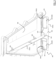
- the movable wall system 260 comprises a first wall member 310(1) and a second wall member 310(2) pivotally coupled to the ceiling portion 305 of the filter seat 111.
- the first wall member 310(1) is pivotally coupled to the ceiling portion 305 by means of two hinge elements 320
- the second wall member 310(2) is pivotally coupled to the ceiling portion 305 by means of further two hinge elements 325. It is understood that similar considerations apply in case the first wall member 310(1) and/or the second wall member 310(2) is/are pivotally coupled to the ceiling portion 305 with a different number of hinge elements or with a different kind of coupling elements.
- the concepts of the present invention can be applied to cases in which the first wall member 310(1) and/or the second wall member 310(2) is/are coupled to a different portion of the filter seat 111, such as the floor portion or the side portions of the filter seat 111.
- the first wall member 310(1) and the second wall member 310(2) are configured to be rotated between:
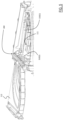
- Figure 4A corresponds to the case in which the air filter unit 112 is located inside the filter seat 111 ( i.e. , when the air filter unit 112 is in the first position), the air filter unit 112 has not been depicted in said figure for the sake of clarity.
- the air introduction opening IN(260) and the air exhausting opening OUT(260) are located on the second wall member 310(2).
- the second wall member 310(2) when the first wall member 310(1) and the second wall member 310(2) are in the unfolded position, the second wall member 310(2) is arranged to obstruct the seat opening 216.
- the obstruction of the seat opening 216 by the second wall member 310(2) when the latter is in the unfolded position is only partial, because air is advantageously allowed to pass through the air introduction opening IN(260) and the air exhausting opening OUT(260).
- the first wall member 310(1) and the second wall member 310(2) are configured to be rotated from the unfolded position to the folded position when the air filter unit 112 is being inserted in the filter seat 111 through the seat opening 216.
- a profiled member 510 is provided on the face of the second wall member 310(2) facing inside the filter seat 111 when the second wall member 310(2) is in the unfolded position (said face being identified in the figures with reference 520 ).
- the profiled member 510 is configured as a cam of a cam system comprising a follower provided as a profiled edge (identified in the figures with reference 530 ) of the first wall member 310(1).
- a rotation of the second wall member 310(2) toward the ceiling portion 305 ( i.e., toward the folded position) caused by a push of the air filter unit 112 while being inserted in the filter seat 111 causes a corresponding rotation of the first wall member 310(1) toward the ceiling portion 305 ( i.e., toward the folded position).
- first wall member 310(1) and a second wall member 310(2) are pivotally coupled to a floor portion 405 of the filter seat 111
- a rotation of the second wall member 310(2) toward the floor portion 405 ( i.e., toward the folded position) caused by a push of the air filter unit 112 while being inserted in the filter seat 111 causes a corresponding rotation of the first wall member 310(1) toward the floor portion 405 ( i.e., toward the folded position).
- one or more elastic biasing elements are provided (in the embodiment of the invention illustrated in Figure 3 , two biasing elements, identified with references 330(1) and 330(2)) and configured to cause the second wall member 310(2) to rotate from the folded position to the unfolded position when the air filter unit 112 is being extracted from the filter seat 111.
- the biasing elements 330(1), 330(2) may be springs biased in such a way that the second wall member 310(2) is rotated from the folded position to the unfolded position when the air filter unit 112 is being extracted from the filter seat 111.
- Such configuration of one or more elastic biasing elements may be provided also in an embodiment wherein the first wall member 310(1) and a second wall member 310(2) are pivotally coupled to a floor portion 405 of the filter seat 111
- the switching between the laundry dryer operative mode and the ambient air dehumidification operative mode of the laundry appliance 100 can be easily performed in a very efficient way.
- the movable wall system 260 according to the embodiments of the present invention is advantageously adapted to accordingly configure the drying air flow system 204 of the laundry appliance 100 by simply switching the wall members 310(1) and 310(2) between the folded and unfolded positions, with said switching that is carried out by simply inserting or removing the air filter unit 112 from the filter seat 111.
- Figure 6A is an enlarged plan view of the second wall member 310(2) according to an embodiment of the resent invention.
- Figure 6B is a sectional view of a portion of the second wall member 310(2) taken along the section line B-B of Figure 6A
- Figure 6C is a sectional view of the second wall member 310(2) taken along the section line C-C of Figure 6A .
- the profiled member 510 of the second wall member 310(2) has a chamfered shape protruding from the face 520.
- the profiled member 510 is advantageously shaped to have a profile such to promote the mutual sliding between the profiled member 510 of the second wall member 310(2) and the profiled edge 530 of the first wall member 310(1) when the second wall member 310(2) moves.
- the movement of the second wall member 310(2) being caused by the air filter unit 112 when being inserted in the filter seat 111 for passing from the unfolded to the folded position, or by the biasing elements 330(1) and 330(2) when the air filter unit 112 is removed from the filter seat 111 for passing from the folded to the unfolded position.
- the profiled member 510 has a shape substantially corresponding to an oblique triangular prism.
- similar considerations apply in case the profiled member 510 has a different shape, provided that it is suitable to promote the mutual sliding between the profiled member 510 of the second wall member 310(2) and the profiled edge 530 of the first wall member 310(1) when the second wall member 310(2) moves avoiding, or at least reducing, jamming occurrences.
- the first wall member 310(1) and particularly its size and position, is set in such a way that the first wall member 310(1) forms an angle ⁇ (visible in Figure 3 ) comprised between 90° and 115° with respect to the ceiling portion 305 when the first wall member 310(1) is in the unfolded position and preferably touches the floor portion 405 of the filter seat 111.
- ⁇ visible in Figure 3
- the angle ⁇ may be advantageously set higher than 90°, so that the first wall member 310(1) is not perpendicular to the floor portion 405 of the filter seat 111 when in the unfolded position.
- this is advantageously obtained by setting the height H of the first wall member 310(1), i.e., the length thereof perpendicular to its rotation axis, greater than the distance between the ceiling portion 305 and the floor portion 405 of the filter seat 111.
- a portion of the drying air flow system 204, and particularly the main air duct 210 and the filter seat 111, are housed in the volume enclosed by the box-like shaped worktop 109 (see Figures 1 , 2A , 2B ).
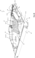
- FIG. 7A is a perspective view of an exemplary worktop 109 embodiment removed from the laundry appliance 100 and without the covering panel 110.
- the worktop 109 defines a box-like structure formed by an upper wall 705, a lower wall 740 (visible in Figure 7B ), and a plurality of lateral walls 708 arranged substantially perpendicularly to the upper wall 705 and to the lower wall 740 so as to form a worktop inner volume.
- Figures 7B and 7C are perspective views of the worktop 109 - from behind and from front, respectively - without the upper wall 705 according to an embodiment of the present invention.
- the worktop 109 is shaped and sized so as to define the main air duct 210 and a number of housing sections adapted to house corresponding components of the air flow system 204 included in the main air duct 210.
- the worktop 109 comprises a demoisturizing housing section 720 for housing the air demoisturizing unit 220 and a heating housing section 730 for housing the air heating unit 230 (see also Figures 2A and 2B ).
- the ceiling portion 305 of the filter seat 111 is defined by a portion of the upper wall 705 of the worktop 109.
- the floor portion 405 of the filter seat 111 is defined by a portion of the lower wall 740 of the worktop 109.
- the upper wall 705 of the worktop 109 is advantageously provided with a removable portion, identified in Figure 7A with reference 750, located at, e.g. , above, the movable wall system 260 for allowing an easy access to the movable wall system 260.
- the movable wall system 260 is at least partially coupled to said removable portion 750 of the upper wall 705, in such a way to allow an extraction of the movable wall system 260 from the worktop 109.
- the extraction of the movable wall system 260 from the worktop 109 may be carried out after having removed the covering panel 110 from the worktop 109, or after having removed a corresponding removable portion (not illustrated) of the covering panel 110 aligned with the removable portion 750 of the upper wall 705.
- the concepts of the present invention can be directly applied in those cases in which ( e.g. , portions of) the main air duct 210 and/or the filter seat 111 are not housed inside the volume enclosed by the worktop 109, but rather they are located outside the worktop 109, such as for example in different positions within the cabinet 105 of the laundry appliance 100.
Landscapes
- Engineering & Computer Science (AREA)
- Textile Engineering (AREA)
- Drying Of Solid Materials (AREA)
Claims (15)
- Waschguttrocknungsgerät (100), umfassend:- ein Gehäuse (105),- eine Waschgutkammer (206), die drehbar in dem Gehäuse eingeschlossen ist, zur Aufnahme von zu trocknendem Waschgut,- ein Trocknungsluftströmungssystem (204) zum Leiten der Luft durch die Waschgutkammer, wobei das Trocknungsluftströmungssystem eine Luftentfeuchtungseinheit (220) umfasst, die zur Entfeuchtung der Luft ausgelegt ist,- einen Filtersitz (111), der in dem Trocknungsströmungssystem angeordnet ist, um einen Luftfilter (112) entfernbar aufzunehmen,- wobei der Luftfilter aus einer ersten Position, in der er in den Filtersitz eingesetzt ist, um die Waschgutkammer verlassende Trocknungsluft zu filtern, in eine zweite Position, in der er von dem Filtersitz entfernt und von dem Gerät gelöst ist, und umgekehrt bewegbar ist,- wobei das Waschguttrocknungsgerät dazu ausgestaltet ist, in einem Waschguttrocknermodus zu arbeiten, wenn sich der Luftfilter in der ersten Position befindet, und in einem Umgebungsluftentfeuchtungsmodus, um Luft in der Umgebung außerhalb des Gehäuses zu entfeuchten, wenn sich der Luftfilter in der zweiten Position befindet,dadurch gekennzeichnet, dass:das Waschguttrocknungsgerät ferner ein bewegliches Wandsystem (260) umfasst, das in dem Filtersitz (111) angeordnet und durch Bewegen des Luftfilters (112) aus einer in die andere der ersten und der zweiten Position dahingehend betätigbar ist, das Trocknungsluftströmungssystem (204) so zu konfigurieren, dass:- das Trocknungsluftströmungssystem dazu ausgestaltet ist, Trocknungsluft in einem im Wesentlichen geschlossenen Luftkreislauf durch die Waschgutkammer und den Luftfilter zu zirkulieren, wenn sich der Luftfilter (112) in der ersten Position befindet, und- die Waschgutkammer durch eine Lufteinführöffnung (IN(260)) und eine Luftauslassöffnung (OUT(260)), die durch das bewegliche Wandsystem in dem Filtersitz bereitgestellt werden, mit der Umgebung außerhalb des Gehäuses in Fluidverbindung gebracht wird, wenn sich der Filter (112) in der zweiten Position befindet,wobei das bewegliche Wandsystem (260) so ausgestaltet ist, dass durch die Betätigung des beweglichen Wandsystems, wenn sich der Luftfilter (112) in der zweiten Position befindet, veranlasst wird, dass das Volumen des Filtersitzes (111) aufgeteilt wird in:- einen ersten Volumenabschnitt (270), der die Lufteinführöffnung (IN(260)) umfasst und Luft von der Umgebung außerhalb des Gehäuses zu der Waschgutkammer (206) leitet, und- einen zweiten Volumenabschnitt (280), der die Luftauslassöffnung (OUT(260)) umfasst und Luft aus der Waschgutkammer zur Umgebung außerhalb des Gehäuses leitet, und zwar im Wesentlichen ohne Mischen mit Luft, die in dem ersten Volumenabschnitt strömt.
- Waschguttrocknungsgerät (100) nach Anspruch 1, wobei das bewegliche Wandsystem (260) ein erstes und ein zweites Wandglied (310(1), 310(2)) umfasst, die schwenkbar an den Filtersitz (111) gekoppelt und dazu ausgelegt sind, zwischen Folgendem gedreht zu werden:- einer zusammengeklappten Position, in der das erste und das zweite Wandglied durch den Luftfilter im Wesentlichen zu einem Deckenabschnitt (305) des Filtersitzes hin gehalten werden, wenn sich der Luftfilter in der ersten Position befindet, und- einer ausgeklappten Position, in der das erste und das zweite Wandglied von dem Deckenabschnitt herabhängen und sich zu einem Bodenabschnitt (405) des Filtersitzes hin erstrecken, wenn sich der Luftfilter in der zweiten Position befindet.
- Waschguttrocknungsgerät (100) nach Anspruch 2, wobei:- der Filtersitz (111) eine Sitzöffnung (216) umfasst, die zwischen dem Deckenabschnitt und dem Bodenabschnitt vorgesehen ist, um den Luftfilter darin aufzunehmen,- das zweite Wandglied (310(2)) des beweglichen Wandsystems (260) die Lufteinführöffnung (IN (260)) und die Luftauslassöffnung (OUT(260)) umfasst, die daran ausgebildet sind, um die Sitzöffnung teilweise zu versperren, wenn sich der Luftfilter (112) in der zweiten Position befindet.
- Waschguttrocknungsgerät (100) nach Anspruch 3, wobei das erste Wandglied (310(1)) und das zweite Wandglied (310(2)) dazu ausgestaltet sind, aus der ausgeklappten Position in die zusammengeklappte Position gedreht zu werden, wenn der Luftfilter (112) durch die Sitzöffnung (216) in den Filtersitz (111) eingeführt wird, um die erste Position zu erreichen.
- Waschguttrocknungsgerät (100) nach einem der Ansprüche 2 bis 4, wobei das zweite Wandglied (310(2)) ein profiliertes Glied (510) an einer ersten Fläche des zweiten Wandglieds umfasst, das in den Filtersitz (111) weist, wenn sich das zweite Wandglied in der ausgeklappten Position befindet, wobei das profilierte Glied als ein Nocken eines Nockensystems ausgestaltet ist, das einen Mitnehmer umfasst, der als ein profilierter Rand (530) des ersten Wandglieds (310(1)) vorgesehen ist, so dass durch die Drehung des zweiten Wandglieds in die zusammengeklappte Position hin eine entsprechende Drehung des ersten Wandglieds zu der zusammengeklappten Position hin veranlasst wird.
- Waschguttrocknungsgerät (100) nach Anspruch 5, wobei das zweite Wandglied (310(2)) mindestens ein elastisches Element (330(1), 330(2)) umfasst, das derart vorgespannt ist, dass das zweite Wandglied aus der zusammengeklappten Position in die ausgeklappte Position gedreht wird, wenn das Filterelement (112) aus dem Filtersitz (111) herausgezogen wird.
- Waschguttrocknungsgerät (100) nach einem der vorhergehenden Ansprüche, wobei das Trocknungsluftströmungssystem (204) eine Luftheizeinheit (230) umfasst, die dazu ausgelegt ist, durch die Entfeuchtungseinheit (220) entfeuchtete Luft zu erhitzen.
- Waschguttrocknungsgerät (100) nach Anspruch 7, wobei:- die Luftentfeuchtungseinheit (220) eine Verdampfungseinheit und die Luftheizeinheit (230) eine Kondensatoreinheit eines Wärmepumpensystems umfasst, oder- die Luftentfeuchtungseinheit (220) eine Luft/Luft-Wärmetauschereinheit und die Luftheizeinheit (230) einen Heizwiderstand umfasst, oder- die Luftentfeuchtungseinheit (220) eine Luft/Wasser-Tauschereinheit und die Luftheizeinheit (230) einen Heizwiderstand umfasst.
- Waschguttrocknungsgerät (100) nach einem der vorhergehenden Ansprüche, wobei der Gehäuse (105) Seitenwände (105(s)) und eine kastenartige Struktur (109) umfasst, die als eine auf den Seitenwänden angeordnete Arbeitsplatte wirkt, um das Innenvolumen des Gehäuses von oben zu verschließen, wobei die kastenartige Struktur einen Luftkanal (210) umfasst, der einen Teil des Trocknungsluftströmungssystems (204) bildet, wobei der Filtersitz (111) in dem Luftkanal zum entfernbaren Aufnehmen des Luftfilters (112) darin angeordnet ist.
- Waschguttrocknungsgerät (100) nach Anspruch 9, wenn abhängig von Anspruch 2, wobei die kastenartige Struktur (109) Folgendes umfasst:- eine obere Wand (705), die den Deckenabschnitt (305) des Filtersitzes (111) definiert,- eine untere Wand, die den Bodenabschnitt (405) des Filtersitzes definiert.
- Arbeitsplatte (109), die dazu ausgestaltet ist, die obere Wand eines Waschguttrocknungsgerätgehäuses (105) zu bilden, indem sie auf den Seitenwänden (105(s)) davon angeordnet ist, um das Innenvolumen des Gehäuses von oben zu schließen, wobei die Arbeitsplatte Folgendes umfasst:- eine kastenartige Struktur, die durch eine obere Wand (705), eine untere Wand und eine Vielzahl von Seitenwänden (708) gebildet wird, die im Wesentlichen senkrecht zu der oberen und der unteren Wand angeordnet sind, um ein Arbeitsplatteninnenvolumen zu bilden,- einen Luftkanal (210), der in dem Arbeitsplatteninnenvolumen angeordnet und mit einer Luftentfeuchtungseinheit (220) versehen ist, die zum Entfeuchten von in dem Luftkanal zirkulierender Luft ausgestaltet ist,- eine Lufteintrittsöffnung (IN(210)) zum Einführen von Luft in den Luftkanal und eine Luftaustrittsöffnung (OUT(210)) zum Ablassen von Luft aus dem Luftkanal,- einen Luftfiltersitz (111), der in Fluidverbindung mit dem Luftkanal angeordnet und zur Aufnahme eines Luftfilters (112) darin ausgeführt ist,- wobei der Luftfilter (112) aus einer ersten Position, in der er in den Filtersitz eingeführt ist, in eine zweite Position, in der der Luftfilter aus dem Filtersitz entfernt und von dem Gerät gelöst ist, und umgekehrt bewegbar ist,gekennzeichnet durch
ein bewegliches Wandsystem (260), das in dem Filtersitz angeordnet ist, wobei das bewegliche Wandsystem durch Bewegen des Luftfilters von einer in die andere der ersten und der zweiten Position betätigbar ist, um den Luftkanal so auszugestalten, dass:a) wenn sich der Luftfilter in der ersten Position befindet:- die Lufteintrittsöffnung (IN(210)) mittels des Luftfilters in Fluidverbindung mit der Austrittsöffnung (OUT(210)) gebracht wird,- die durch die Lufteintrittsöffnung (IN(210)) in den Luftkanal eintretende Luft mittels des Luftkanals durch den Luftfilter hindurch auf die Luftaustrittsöffnung (OUT(210)) zu getrieben wird,b) wenn sich der Luftfilter in der zweiten Position befindet:- die Lufteintrittsöffnung (IN(210)) und die Luftaustrittsöffnung (OUT(210)) mittels einer Lufteinführöffnung (IN(260)) und einer Luftauslassöffnung (OUT(260)), die durch das bewegliche Wandsystem (260) in dem Filtersitz bereitgestellt sind, mit der Umgebung außerhalb des Arbeitsplatteninnenvolumens in Fluidverbindung gebracht werden,- Luft, die durch die Lufteintrittsöffnung (IN(210)) in den Luftkanal eintritt, durch die Luftauslassöffnung (OUT(260)) zur Umgebung außerhalb des Arbeitsplatteninnenvolumens abgeführt wird,- die Luftaustrittsöffnung (OUT(210)) mit Luft versorgt wird, die von der Umgebung außerhalb des Arbeitsplatteninnenvolumens durch die Lufteinführöffnung (IN(260)) kommt, und zwar im Wesentlichen ohne Mischen mit Luft, die durch die Lufteinlassöffnung in den Luftkanal eintritt und durch die Luftauslassöffnung (OUT(260)) zur Umgebung außerhalb des Arbeitsplatteninnenvolumens abgeführt wird. - Arbeitsplatte (109) nach Anspruch 11, wobei der Luftkanal (210) ferner mit einer Luftheizeinheit (230) versehen ist, die dazu ausgestaltet ist, durch die Entfeuchtungseinheit (220) entfeuchtete Luft zu erhitzen.
- Arbeitsplatte (109) nach Anspruch 11 oder 12, wobei die obere Wand (705) einen entfernbaren Abschnitt (750) umfasst, der sich an dem beweglichen Wandsystem (260) zum Zugriff auf das bewegliche Wandsystem befindet.
- Arbeitsplatte (109) nach Anspruch 13, wobei das bewegliche Wandsystem (260) mindestens teilweise an den entfernbaren Abschnitt (750) der oberen Wand (705) gekoppelt ist.
- Verfahren zum Betreiben eines Waschguttrocknungsgeräts (100) nach einem der Ansprüche 1 bis 10 in einem Waschguttrocknermodus, um in der Waschgutkammer (206) enthaltenes Waschgut zu trocknen, oder in einem Umgebungsluftentfeuchtungsmodus, um Luft in der Umgebung außerhalb des Gehäuses (105) des Geräts zu entfeuchten, wobei das Verfahren Folgendes umfasst:- Bereitstellen des Luftfilters (112) in der ersten Position, wodurch das Trocknungsluftströmungssystem (204) zum Zirkulieren von Trocknungsluft in einem im Wesentlichen geschlossenen Luftkreislauf durch die Waschgutkammer ausgestaltet wird, oder- Bereitstellen des Luftfilters (112) in der zweiten Position, wodurch die Waschgutkammer mittels der Lufteinführöffnung (IN(260)) und der Luftauslassöffnung (OUT(260)), die durch das bewegliche Wandsystem (260) in dem Filtersitz (111) bereitgestellt sind, mit der Umgebung außerhalb des Gehäuses in Fluidverbindung gebracht wird.
Applications Claiming Priority (1)
| Application Number | Priority Date | Filing Date | Title |
|---|---|---|---|
| PCT/EP2020/087943 WO2022144070A1 (en) | 2020-12-28 | 2020-12-28 | Laundry drying appliance with ambient air dehumidification operation mode |
Publications (2)
| Publication Number | Publication Date |
|---|---|
| EP4267789A1 EP4267789A1 (de) | 2023-11-01 |
| EP4267789B1 true EP4267789B1 (de) | 2024-12-18 |
Family
ID=74175866
Family Applications (1)
| Application Number | Title | Priority Date | Filing Date |
|---|---|---|---|
| EP20839116.9A Active EP4267789B1 (de) | 2020-12-28 | 2020-12-28 | Wäschetrocknungsgerät mit betriebsmodus zur umgebungsluftentfeuchtung |
Country Status (2)
| Country | Link |
|---|---|
| EP (1) | EP4267789B1 (de) |
| WO (1) | WO2022144070A1 (de) |
Families Citing this family (2)
| Publication number | Priority date | Publication date | Assignee | Title |
|---|---|---|---|---|
| EP4556619A4 (de) * | 2022-08-10 | 2025-10-22 | Lg Electronics Inc | Vorrichtung zur behandlung von kleidungsstücken |
| CN117329139A (zh) * | 2023-08-03 | 2024-01-02 | 珠海格力电器股份有限公司 | 双吸离心风机、烘干系统及衣物处理设备 |
Family Cites Families (6)
| Publication number | Priority date | Publication date | Assignee | Title |
|---|---|---|---|---|
| DE3710615A1 (de) * | 1987-03-31 | 1988-10-20 | Bosch Siemens Hausgeraete | Zum waschen und trocknen eingerichtete waeschebehandlungsmaschine |
| GB2262595B (en) * | 1991-12-16 | 1996-01-31 | Merloni Elettrodomestici Spa | Laundry washing and drying machine |
| JP2007319458A (ja) * | 2006-06-01 | 2007-12-13 | Matsushita Electric Ind Co Ltd | 洗濯乾燥機 |
| DE102008043176B4 (de) * | 2008-10-24 | 2021-08-26 | BSH Hausgeräte GmbH | Trockner mit Wärmepumpe, Verfahren zu seinem Betrieb und Verfahren zur Klimatisierung eines Raumes |
| DE102012212162A1 (de) | 2012-07-11 | 2014-01-16 | BSH Bosch und Siemens Hausgeräte GmbH | Trockner mit Wärmepumpe mit zusätzlicher Eignung für eine Raumentfeuchtung sowie Verfahren zu dessen Betrieb |
| EP2843100B1 (de) * | 2013-08-30 | 2017-08-09 | Electrolux Appliances Aktiebolag | Waschtrockner mit Wasserfilter |
-
2020
- 2020-12-28 WO PCT/EP2020/087943 patent/WO2022144070A1/en not_active Ceased
- 2020-12-28 EP EP20839116.9A patent/EP4267789B1/de active Active
Also Published As
| Publication number | Publication date |
|---|---|
| EP4267789A1 (de) | 2023-11-01 |
| WO2022144070A1 (en) | 2022-07-07 |
Similar Documents
| Publication | Publication Date | Title |
|---|---|---|
| US9903067B2 (en) | Laundry machine | |
| EP2870283B1 (de) | Wäschetrockner | |
| CN105492681B (zh) | 具有防过热系统的洗衣设备 | |
| EP2870284B1 (de) | Wäschetrockner | |
| KR102052373B1 (ko) | 의류처리장치 | |
| EP2423376B1 (de) | Wäschebehandlungsmaschine | |
| EP2843103B1 (de) | Gerät zum trocknen von wäsche mit zusätzlichem entfuslungsfiter | |
| KR102201868B1 (ko) | 의류건조기 | |
| KR20150009326A (ko) | 의류 건조장치 | |
| EP4267789B1 (de) | Wäschetrocknungsgerät mit betriebsmodus zur umgebungsluftentfeuchtung | |
| KR20230063654A (ko) | 건조 겸용 세탁기 | |
| KR20120022364A (ko) | 세탁장치 | |
| KR20220069779A (ko) | 건조기 | |
| WO2014177432A1 (en) | Heat pump laundry treatment apparatus | |
| KR101319881B1 (ko) | 복합 의류 처리 장치 | |
| AU2018274956A1 (en) | Laundry Dryer Apparatus | |
| KR102017695B1 (ko) | 의류처리장치 | |
| EP2843112B1 (de) | Wäschetrockner mit Drehtrommel | |
| US12404622B2 (en) | Clothes treating apparatus | |
| US12516466B2 (en) | Laundry appliance filter with biasing elements | |
| US12398501B2 (en) | Laundry appliance drainage | |
| CN1936155A (zh) | 滚筒式洗衣干衣机 | |
| KR20230105205A (ko) | 필터 조립체 및 이를 포함하는 세탁기 | |
| US12460343B2 (en) | Laundry appliance filter assembly retention latch | |
| US20250341039A1 (en) | Laundry appliance air filter with labyrinth seal |
Legal Events
| Date | Code | Title | Description |
|---|---|---|---|
| STAA | Information on the status of an ep patent application or granted ep patent |
Free format text: STATUS: UNKNOWN |
|
| STAA | Information on the status of an ep patent application or granted ep patent |
Free format text: STATUS: THE INTERNATIONAL PUBLICATION HAS BEEN MADE |
|
| PUAI | Public reference made under article 153(3) epc to a published international application that has entered the european phase |
Free format text: ORIGINAL CODE: 0009012 |
|
| STAA | Information on the status of an ep patent application or granted ep patent |
Free format text: STATUS: REQUEST FOR EXAMINATION WAS MADE |
|
| 17P | Request for examination filed |
Effective date: 20230728 |
|
| AK | Designated contracting states |
Kind code of ref document: A1 Designated state(s): AL AT BE BG CH CY CZ DE DK EE ES FI FR GB GR HR HU IE IS IT LI LT LU LV MC MK MT NL NO PL PT RO RS SE SI SK SM TR |
|
| DAV | Request for validation of the european patent (deleted) | ||
| DAX | Request for extension of the european patent (deleted) | ||
| GRAP | Despatch of communication of intention to grant a patent |
Free format text: ORIGINAL CODE: EPIDOSNIGR1 |
|
| STAA | Information on the status of an ep patent application or granted ep patent |
Free format text: STATUS: GRANT OF PATENT IS INTENDED |
|
| INTG | Intention to grant announced |
Effective date: 20240515 |
|
| P01 | Opt-out of the competence of the unified patent court (upc) registered |
Free format text: CASE NUMBER: APP_36549/2024 Effective date: 20240619 |
|
| GRAJ | Information related to disapproval of communication of intention to grant by the applicant or resumption of examination proceedings by the epo deleted |
Free format text: ORIGINAL CODE: EPIDOSDIGR1 |
|
| STAA | Information on the status of an ep patent application or granted ep patent |
Free format text: STATUS: REQUEST FOR EXAMINATION WAS MADE |
|
| GRAP | Despatch of communication of intention to grant a patent |
Free format text: ORIGINAL CODE: EPIDOSNIGR1 |
|
| STAA | Information on the status of an ep patent application or granted ep patent |
Free format text: STATUS: GRANT OF PATENT IS INTENDED |
|
| INTC | Intention to grant announced (deleted) | ||
| INTG | Intention to grant announced |
Effective date: 20240923 |
|
| GRAS | Grant fee paid |
Free format text: ORIGINAL CODE: EPIDOSNIGR3 |
|
| GRAA | (expected) grant |
Free format text: ORIGINAL CODE: 0009210 |
|
| STAA | Information on the status of an ep patent application or granted ep patent |
Free format text: STATUS: THE PATENT HAS BEEN GRANTED |
|
| AK | Designated contracting states |
Kind code of ref document: B1 Designated state(s): AL AT BE BG CH CY CZ DE DK EE ES FI FR GB GR HR HU IE IS IT LI LT LU LV MC MK MT NL NO PL PT RO RS SE SI SK SM TR |
|
| REG | Reference to a national code |
Ref country code: CH Ref legal event code: EP |
|
| REG | Reference to a national code |
Ref country code: DE Ref legal event code: R096 Ref document number: 602020043469 Country of ref document: DE |
|
| REG | Reference to a national code |
Ref country code: IE Ref legal event code: FG4D |
|
| REG | Reference to a national code |
Ref country code: LT Ref legal event code: MG9D |
|
| PG25 | Lapsed in a contracting state [announced via postgrant information from national office to epo] |
Ref country code: HR Free format text: LAPSE BECAUSE OF FAILURE TO SUBMIT A TRANSLATION OF THE DESCRIPTION OR TO PAY THE FEE WITHIN THE PRESCRIBED TIME-LIMIT Effective date: 20241218 |
|
| PG25 | Lapsed in a contracting state [announced via postgrant information from national office to epo] |
Ref country code: FI Free format text: LAPSE BECAUSE OF FAILURE TO SUBMIT A TRANSLATION OF THE DESCRIPTION OR TO PAY THE FEE WITHIN THE PRESCRIBED TIME-LIMIT Effective date: 20241218 |
|
| PG25 | Lapsed in a contracting state [announced via postgrant information from national office to epo] |
Ref country code: BG Free format text: LAPSE BECAUSE OF FAILURE TO SUBMIT A TRANSLATION OF THE DESCRIPTION OR TO PAY THE FEE WITHIN THE PRESCRIBED TIME-LIMIT Effective date: 20241218 |
|
| PG25 | Lapsed in a contracting state [announced via postgrant information from national office to epo] |
Ref country code: NO Free format text: LAPSE BECAUSE OF FAILURE TO SUBMIT A TRANSLATION OF THE DESCRIPTION OR TO PAY THE FEE WITHIN THE PRESCRIBED TIME-LIMIT Effective date: 20250318 |
|
| REG | Reference to a national code |
Ref country code: NL Ref legal event code: MP Effective date: 20241218 |
|
| PG25 | Lapsed in a contracting state [announced via postgrant information from national office to epo] |
Ref country code: GR Free format text: LAPSE BECAUSE OF FAILURE TO SUBMIT A TRANSLATION OF THE DESCRIPTION OR TO PAY THE FEE WITHIN THE PRESCRIBED TIME-LIMIT Effective date: 20250319 Ref country code: LV Free format text: LAPSE BECAUSE OF FAILURE TO SUBMIT A TRANSLATION OF THE DESCRIPTION OR TO PAY THE FEE WITHIN THE PRESCRIBED TIME-LIMIT Effective date: 20241218 |
|
| PG25 | Lapsed in a contracting state [announced via postgrant information from national office to epo] |
Ref country code: RS Free format text: LAPSE BECAUSE OF FAILURE TO SUBMIT A TRANSLATION OF THE DESCRIPTION OR TO PAY THE FEE WITHIN THE PRESCRIBED TIME-LIMIT Effective date: 20250318 |
|
| PG25 | Lapsed in a contracting state [announced via postgrant information from national office to epo] |
Ref country code: NL Free format text: LAPSE BECAUSE OF FAILURE TO SUBMIT A TRANSLATION OF THE DESCRIPTION OR TO PAY THE FEE WITHIN THE PRESCRIBED TIME-LIMIT Effective date: 20241218 |
|
| REG | Reference to a national code |
Ref country code: AT Ref legal event code: MK05 Ref document number: 1752313 Country of ref document: AT Kind code of ref document: T Effective date: 20241218 |
|
| PG25 | Lapsed in a contracting state [announced via postgrant information from national office to epo] |
Ref country code: SM Free format text: LAPSE BECAUSE OF FAILURE TO SUBMIT A TRANSLATION OF THE DESCRIPTION OR TO PAY THE FEE WITHIN THE PRESCRIBED TIME-LIMIT Effective date: 20241218 |
|
| PG25 | Lapsed in a contracting state [announced via postgrant information from national office to epo] |
Ref country code: PL Free format text: LAPSE BECAUSE OF FAILURE TO SUBMIT A TRANSLATION OF THE DESCRIPTION OR TO PAY THE FEE WITHIN THE PRESCRIBED TIME-LIMIT Effective date: 20241218 |
|
| PG25 | Lapsed in a contracting state [announced via postgrant information from national office to epo] |
Ref country code: ES Free format text: LAPSE BECAUSE OF FAILURE TO SUBMIT A TRANSLATION OF THE DESCRIPTION OR TO PAY THE FEE WITHIN THE PRESCRIBED TIME-LIMIT Effective date: 20241218 |
|
| PG25 | Lapsed in a contracting state [announced via postgrant information from national office to epo] |
Ref country code: IS Free format text: LAPSE BECAUSE OF FAILURE TO SUBMIT A TRANSLATION OF THE DESCRIPTION OR TO PAY THE FEE WITHIN THE PRESCRIBED TIME-LIMIT Effective date: 20250418 |
|
| PG25 | Lapsed in a contracting state [announced via postgrant information from national office to epo] |
Ref country code: PT Free format text: LAPSE BECAUSE OF FAILURE TO SUBMIT A TRANSLATION OF THE DESCRIPTION OR TO PAY THE FEE WITHIN THE PRESCRIBED TIME-LIMIT Effective date: 20250421 |
|
| PG25 | Lapsed in a contracting state [announced via postgrant information from national office to epo] |
Ref country code: EE Free format text: LAPSE BECAUSE OF FAILURE TO SUBMIT A TRANSLATION OF THE DESCRIPTION OR TO PAY THE FEE WITHIN THE PRESCRIBED TIME-LIMIT Effective date: 20241218 |
|
| PG25 | Lapsed in a contracting state [announced via postgrant information from national office to epo] |
Ref country code: RO Free format text: LAPSE BECAUSE OF FAILURE TO SUBMIT A TRANSLATION OF THE DESCRIPTION OR TO PAY THE FEE WITHIN THE PRESCRIBED TIME-LIMIT Effective date: 20241218 Ref country code: AT Free format text: LAPSE BECAUSE OF FAILURE TO SUBMIT A TRANSLATION OF THE DESCRIPTION OR TO PAY THE FEE WITHIN THE PRESCRIBED TIME-LIMIT Effective date: 20241218 |
|
| PG25 | Lapsed in a contracting state [announced via postgrant information from national office to epo] |
Ref country code: SK Free format text: LAPSE BECAUSE OF FAILURE TO SUBMIT A TRANSLATION OF THE DESCRIPTION OR TO PAY THE FEE WITHIN THE PRESCRIBED TIME-LIMIT Effective date: 20241218 |
|
| PG25 | Lapsed in a contracting state [announced via postgrant information from national office to epo] |
Ref country code: CZ Free format text: LAPSE BECAUSE OF FAILURE TO SUBMIT A TRANSLATION OF THE DESCRIPTION OR TO PAY THE FEE WITHIN THE PRESCRIBED TIME-LIMIT Effective date: 20241218 |
|
| PG25 | Lapsed in a contracting state [announced via postgrant information from national office to epo] |
Ref country code: IT Free format text: LAPSE BECAUSE OF FAILURE TO SUBMIT A TRANSLATION OF THE DESCRIPTION OR TO PAY THE FEE WITHIN THE PRESCRIBED TIME-LIMIT Effective date: 20241218 |
|
| REG | Reference to a national code |
Ref country code: CH Ref legal event code: PL |
|
| PG25 | Lapsed in a contracting state [announced via postgrant information from national office to epo] |
Ref country code: LU Free format text: LAPSE BECAUSE OF NON-PAYMENT OF DUE FEES Effective date: 20241228 |
|
| PG25 | Lapsed in a contracting state [announced via postgrant information from national office to epo] |
Ref country code: SE Free format text: LAPSE BECAUSE OF FAILURE TO SUBMIT A TRANSLATION OF THE DESCRIPTION OR TO PAY THE FEE WITHIN THE PRESCRIBED TIME-LIMIT Effective date: 20241218 |
|
| PG25 | Lapsed in a contracting state [announced via postgrant information from national office to epo] |
Ref country code: MC Free format text: LAPSE BECAUSE OF FAILURE TO SUBMIT A TRANSLATION OF THE DESCRIPTION OR TO PAY THE FEE WITHIN THE PRESCRIBED TIME-LIMIT Effective date: 20241218 |
|
| REG | Reference to a national code |
Ref country code: DE Ref legal event code: R097 Ref document number: 602020043469 Country of ref document: DE |
|
| REG | Reference to a national code |
Ref country code: BE Ref legal event code: MM Effective date: 20241231 |
|
| PG25 | Lapsed in a contracting state [announced via postgrant information from national office to epo] |
Ref country code: DK Free format text: LAPSE BECAUSE OF FAILURE TO SUBMIT A TRANSLATION OF THE DESCRIPTION OR TO PAY THE FEE WITHIN THE PRESCRIBED TIME-LIMIT Effective date: 20241218 |
|
| PG25 | Lapsed in a contracting state [announced via postgrant information from national office to epo] |
Ref country code: BE Free format text: LAPSE BECAUSE OF NON-PAYMENT OF DUE FEES Effective date: 20241231 |
|
| PG25 | Lapsed in a contracting state [announced via postgrant information from national office to epo] |
Ref country code: CH Free format text: LAPSE BECAUSE OF NON-PAYMENT OF DUE FEES Effective date: 20241231 |
|
| PG25 | Lapsed in a contracting state [announced via postgrant information from national office to epo] |
Ref country code: IE Free format text: LAPSE BECAUSE OF NON-PAYMENT OF DUE FEES Effective date: 20241228 |
|
| PLBE | No opposition filed within time limit |
Free format text: ORIGINAL CODE: 0009261 |
|
| STAA | Information on the status of an ep patent application or granted ep patent |
Free format text: STATUS: NO OPPOSITION FILED WITHIN TIME LIMIT |
|
| 26N | No opposition filed |
Effective date: 20250919 |
|
| PGFP | Annual fee paid to national office [announced via postgrant information from national office to epo] |
Ref country code: GB Payment date: 20251223 Year of fee payment: 6 |
|
| PGFP | Annual fee paid to national office [announced via postgrant information from national office to epo] |
Ref country code: FR Payment date: 20251223 Year of fee payment: 6 |
|
| PGFP | Annual fee paid to national office [announced via postgrant information from national office to epo] |
Ref country code: DE Payment date: 20251229 Year of fee payment: 6 |