EP4267864B1 - Doppelschichtige bremsscheibe aus nickelfreiem stahl und herstellungsverfahren - Google Patents
Doppelschichtige bremsscheibe aus nickelfreiem stahl und herstellungsverfahren Download PDFInfo
- Publication number
- EP4267864B1 EP4267864B1 EP21844409.9A EP21844409A EP4267864B1 EP 4267864 B1 EP4267864 B1 EP 4267864B1 EP 21844409 A EP21844409 A EP 21844409A EP 4267864 B1 EP4267864 B1 EP 4267864B1
- Authority
- EP
- European Patent Office
- Prior art keywords
- technique
- base layer
- steel
- braking
- braking band
- Prior art date
- Legal status (The legal status is an assumption and is not a legal conclusion. Google has not performed a legal analysis and makes no representation as to the accuracy of the status listed.)
- Active
Links
Images




Classifications
-
- F—MECHANICAL ENGINEERING; LIGHTING; HEATING; WEAPONS; BLASTING
- F16—ENGINEERING ELEMENTS AND UNITS; GENERAL MEASURES FOR PRODUCING AND MAINTAINING EFFECTIVE FUNCTIONING OF MACHINES OR INSTALLATIONS; THERMAL INSULATION IN GENERAL
- F16D—COUPLINGS FOR TRANSMITTING ROTATION; CLUTCHES; BRAKES
- F16D65/00—Parts or details
- F16D65/02—Braking members; Mounting thereof
- F16D65/12—Discs; Drums for disc brakes
- F16D65/127—Discs; Drums for disc brakes characterised by properties of the disc surface; Discs lined with friction material
-
- C—CHEMISTRY; METALLURGY
- C23—COATING METALLIC MATERIAL; COATING MATERIAL WITH METALLIC MATERIAL; CHEMICAL SURFACE TREATMENT; DIFFUSION TREATMENT OF METALLIC MATERIAL; COATING BY VACUUM EVAPORATION, BY SPUTTERING, BY ION IMPLANTATION OR BY CHEMICAL VAPOUR DEPOSITION, IN GENERAL; INHIBITING CORROSION OF METALLIC MATERIAL OR INCRUSTATION IN GENERAL
- C23C—COATING METALLIC MATERIAL; COATING MATERIAL WITH METALLIC MATERIAL; SURFACE TREATMENT OF METALLIC MATERIAL BY DIFFUSION INTO THE SURFACE, BY CHEMICAL CONVERSION OR SUBSTITUTION; COATING BY VACUUM EVAPORATION, BY SPUTTERING, BY ION IMPLANTATION OR BY CHEMICAL VAPOUR DEPOSITION, IN GENERAL
- C23C10/00—Solid state diffusion of only metal elements or silicon into metallic material surfaces
- C23C10/02—Pretreatment of the material to be coated
-
- C—CHEMISTRY; METALLURGY
- C23—COATING METALLIC MATERIAL; COATING MATERIAL WITH METALLIC MATERIAL; CHEMICAL SURFACE TREATMENT; DIFFUSION TREATMENT OF METALLIC MATERIAL; COATING BY VACUUM EVAPORATION, BY SPUTTERING, BY ION IMPLANTATION OR BY CHEMICAL VAPOUR DEPOSITION, IN GENERAL; INHIBITING CORROSION OF METALLIC MATERIAL OR INCRUSTATION IN GENERAL
- C23C—COATING METALLIC MATERIAL; COATING MATERIAL WITH METALLIC MATERIAL; SURFACE TREATMENT OF METALLIC MATERIAL BY DIFFUSION INTO THE SURFACE, BY CHEMICAL CONVERSION OR SUBSTITUTION; COATING BY VACUUM EVAPORATION, BY SPUTTERING, BY ION IMPLANTATION OR BY CHEMICAL VAPOUR DEPOSITION, IN GENERAL
- C23C10/00—Solid state diffusion of only metal elements or silicon into metallic material surfaces
- C23C10/18—Solid state diffusion of only metal elements or silicon into metallic material surfaces using liquids, e.g. salt baths, liquid suspensions
- C23C10/20—Solid state diffusion of only metal elements or silicon into metallic material surfaces using liquids, e.g. salt baths, liquid suspensions only one element being diffused
- C23C10/22—Metal melt containing the element to be diffused
-
- C—CHEMISTRY; METALLURGY
- C23—COATING METALLIC MATERIAL; COATING MATERIAL WITH METALLIC MATERIAL; CHEMICAL SURFACE TREATMENT; DIFFUSION TREATMENT OF METALLIC MATERIAL; COATING BY VACUUM EVAPORATION, BY SPUTTERING, BY ION IMPLANTATION OR BY CHEMICAL VAPOUR DEPOSITION, IN GENERAL; INHIBITING CORROSION OF METALLIC MATERIAL OR INCRUSTATION IN GENERAL
- C23C—COATING METALLIC MATERIAL; COATING MATERIAL WITH METALLIC MATERIAL; SURFACE TREATMENT OF METALLIC MATERIAL BY DIFFUSION INTO THE SURFACE, BY CHEMICAL CONVERSION OR SUBSTITUTION; COATING BY VACUUM EVAPORATION, BY SPUTTERING, BY ION IMPLANTATION OR BY CHEMICAL VAPOUR DEPOSITION, IN GENERAL
- C23C10/00—Solid state diffusion of only metal elements or silicon into metallic material surfaces
- C23C10/60—After-treatment
-
- C—CHEMISTRY; METALLURGY
- C23—COATING METALLIC MATERIAL; COATING MATERIAL WITH METALLIC MATERIAL; CHEMICAL SURFACE TREATMENT; DIFFUSION TREATMENT OF METALLIC MATERIAL; COATING BY VACUUM EVAPORATION, BY SPUTTERING, BY ION IMPLANTATION OR BY CHEMICAL VAPOUR DEPOSITION, IN GENERAL; INHIBITING CORROSION OF METALLIC MATERIAL OR INCRUSTATION IN GENERAL
- C23C—COATING METALLIC MATERIAL; COATING MATERIAL WITH METALLIC MATERIAL; SURFACE TREATMENT OF METALLIC MATERIAL BY DIFFUSION INTO THE SURFACE, BY CHEMICAL CONVERSION OR SUBSTITUTION; COATING BY VACUUM EVAPORATION, BY SPUTTERING, BY ION IMPLANTATION OR BY CHEMICAL VAPOUR DEPOSITION, IN GENERAL
- C23C24/00—Coating starting from inorganic powder
- C23C24/08—Coating starting from inorganic powder by application of heat or pressure and heat
-
- C—CHEMISTRY; METALLURGY
- C23—COATING METALLIC MATERIAL; COATING MATERIAL WITH METALLIC MATERIAL; CHEMICAL SURFACE TREATMENT; DIFFUSION TREATMENT OF METALLIC MATERIAL; COATING BY VACUUM EVAPORATION, BY SPUTTERING, BY ION IMPLANTATION OR BY CHEMICAL VAPOUR DEPOSITION, IN GENERAL; INHIBITING CORROSION OF METALLIC MATERIAL OR INCRUSTATION IN GENERAL
- C23C—COATING METALLIC MATERIAL; COATING MATERIAL WITH METALLIC MATERIAL; SURFACE TREATMENT OF METALLIC MATERIAL BY DIFFUSION INTO THE SURFACE, BY CHEMICAL CONVERSION OR SUBSTITUTION; COATING BY VACUUM EVAPORATION, BY SPUTTERING, BY ION IMPLANTATION OR BY CHEMICAL VAPOUR DEPOSITION, IN GENERAL
- C23C24/00—Coating starting from inorganic powder
- C23C24/08—Coating starting from inorganic powder by application of heat or pressure and heat
- C23C24/082—Coating starting from inorganic powder by application of heat or pressure and heat without intermediate formation of a liquid in the layer
-
- C—CHEMISTRY; METALLURGY
- C23—COATING METALLIC MATERIAL; COATING MATERIAL WITH METALLIC MATERIAL; CHEMICAL SURFACE TREATMENT; DIFFUSION TREATMENT OF METALLIC MATERIAL; COATING BY VACUUM EVAPORATION, BY SPUTTERING, BY ION IMPLANTATION OR BY CHEMICAL VAPOUR DEPOSITION, IN GENERAL; INHIBITING CORROSION OF METALLIC MATERIAL OR INCRUSTATION IN GENERAL
- C23C—COATING METALLIC MATERIAL; COATING MATERIAL WITH METALLIC MATERIAL; SURFACE TREATMENT OF METALLIC MATERIAL BY DIFFUSION INTO THE SURFACE, BY CHEMICAL CONVERSION OR SUBSTITUTION; COATING BY VACUUM EVAPORATION, BY SPUTTERING, BY ION IMPLANTATION OR BY CHEMICAL VAPOUR DEPOSITION, IN GENERAL
- C23C24/00—Coating starting from inorganic powder
- C23C24/08—Coating starting from inorganic powder by application of heat or pressure and heat
- C23C24/082—Coating starting from inorganic powder by application of heat or pressure and heat without intermediate formation of a liquid in the layer
- C23C24/085—Coating with metallic material, i.e. metals or metal alloys, optionally comprising hard particles, e.g. oxides, carbides or nitrides
-
- C—CHEMISTRY; METALLURGY
- C23—COATING METALLIC MATERIAL; COATING MATERIAL WITH METALLIC MATERIAL; CHEMICAL SURFACE TREATMENT; DIFFUSION TREATMENT OF METALLIC MATERIAL; COATING BY VACUUM EVAPORATION, BY SPUTTERING, BY ION IMPLANTATION OR BY CHEMICAL VAPOUR DEPOSITION, IN GENERAL; INHIBITING CORROSION OF METALLIC MATERIAL OR INCRUSTATION IN GENERAL
- C23C—COATING METALLIC MATERIAL; COATING MATERIAL WITH METALLIC MATERIAL; SURFACE TREATMENT OF METALLIC MATERIAL BY DIFFUSION INTO THE SURFACE, BY CHEMICAL CONVERSION OR SUBSTITUTION; COATING BY VACUUM EVAPORATION, BY SPUTTERING, BY ION IMPLANTATION OR BY CHEMICAL VAPOUR DEPOSITION, IN GENERAL
- C23C24/00—Coating starting from inorganic powder
- C23C24/08—Coating starting from inorganic powder by application of heat or pressure and heat
- C23C24/082—Coating starting from inorganic powder by application of heat or pressure and heat without intermediate formation of a liquid in the layer
- C23C24/085—Coating with metallic material, i.e. metals or metal alloys, optionally comprising hard particles, e.g. oxides, carbides or nitrides
- C23C24/087—Coating with metal alloys or metal elements only
-
- C—CHEMISTRY; METALLURGY
- C23—COATING METALLIC MATERIAL; COATING MATERIAL WITH METALLIC MATERIAL; CHEMICAL SURFACE TREATMENT; DIFFUSION TREATMENT OF METALLIC MATERIAL; COATING BY VACUUM EVAPORATION, BY SPUTTERING, BY ION IMPLANTATION OR BY CHEMICAL VAPOUR DEPOSITION, IN GENERAL; INHIBITING CORROSION OF METALLIC MATERIAL OR INCRUSTATION IN GENERAL
- C23C—COATING METALLIC MATERIAL; COATING MATERIAL WITH METALLIC MATERIAL; SURFACE TREATMENT OF METALLIC MATERIAL BY DIFFUSION INTO THE SURFACE, BY CHEMICAL CONVERSION OR SUBSTITUTION; COATING BY VACUUM EVAPORATION, BY SPUTTERING, BY ION IMPLANTATION OR BY CHEMICAL VAPOUR DEPOSITION, IN GENERAL
- C23C28/00—Coating for obtaining at least two superposed coatings either by methods not provided for in a single one of groups C23C2/00 - C23C26/00 or by combinations of methods provided for in subclasses C23C and C25C or C25D
- C23C28/30—Coatings combining at least one metallic layer and at least one inorganic non-metallic layer
-
- C—CHEMISTRY; METALLURGY
- C23—COATING METALLIC MATERIAL; COATING MATERIAL WITH METALLIC MATERIAL; CHEMICAL SURFACE TREATMENT; DIFFUSION TREATMENT OF METALLIC MATERIAL; COATING BY VACUUM EVAPORATION, BY SPUTTERING, BY ION IMPLANTATION OR BY CHEMICAL VAPOUR DEPOSITION, IN GENERAL; INHIBITING CORROSION OF METALLIC MATERIAL OR INCRUSTATION IN GENERAL
- C23C—COATING METALLIC MATERIAL; COATING MATERIAL WITH METALLIC MATERIAL; SURFACE TREATMENT OF METALLIC MATERIAL BY DIFFUSION INTO THE SURFACE, BY CHEMICAL CONVERSION OR SUBSTITUTION; COATING BY VACUUM EVAPORATION, BY SPUTTERING, BY ION IMPLANTATION OR BY CHEMICAL VAPOUR DEPOSITION, IN GENERAL
- C23C28/00—Coating for obtaining at least two superposed coatings either by methods not provided for in a single one of groups C23C2/00 - C23C26/00 or by combinations of methods provided for in subclasses C23C and C25C or C25D
- C23C28/30—Coatings combining at least one metallic layer and at least one inorganic non-metallic layer
- C23C28/32—Coatings combining at least one metallic layer and at least one inorganic non-metallic layer including at least one pure metallic layer
- C23C28/321—Coatings combining at least one metallic layer and at least one inorganic non-metallic layer including at least one pure metallic layer with at least one metal alloy layer
-
- C—CHEMISTRY; METALLURGY
- C23—COATING METALLIC MATERIAL; COATING MATERIAL WITH METALLIC MATERIAL; CHEMICAL SURFACE TREATMENT; DIFFUSION TREATMENT OF METALLIC MATERIAL; COATING BY VACUUM EVAPORATION, BY SPUTTERING, BY ION IMPLANTATION OR BY CHEMICAL VAPOUR DEPOSITION, IN GENERAL; INHIBITING CORROSION OF METALLIC MATERIAL OR INCRUSTATION IN GENERAL
- C23C—COATING METALLIC MATERIAL; COATING MATERIAL WITH METALLIC MATERIAL; SURFACE TREATMENT OF METALLIC MATERIAL BY DIFFUSION INTO THE SURFACE, BY CHEMICAL CONVERSION OR SUBSTITUTION; COATING BY VACUUM EVAPORATION, BY SPUTTERING, BY ION IMPLANTATION OR BY CHEMICAL VAPOUR DEPOSITION, IN GENERAL
- C23C28/00—Coating for obtaining at least two superposed coatings either by methods not provided for in a single one of groups C23C2/00 - C23C26/00 or by combinations of methods provided for in subclasses C23C and C25C or C25D
- C23C28/30—Coatings combining at least one metallic layer and at least one inorganic non-metallic layer
- C23C28/34—Coatings combining at least one metallic layer and at least one inorganic non-metallic layer including at least one inorganic non-metallic material layer, e.g. metal carbide, nitride, boride, silicide layer and their mixtures, enamels, phosphates and sulphates
- C23C28/341—Coatings combining at least one metallic layer and at least one inorganic non-metallic layer including at least one inorganic non-metallic material layer, e.g. metal carbide, nitride, boride, silicide layer and their mixtures, enamels, phosphates and sulphates with at least one carbide layer
-
- C—CHEMISTRY; METALLURGY
- C23—COATING METALLIC MATERIAL; COATING MATERIAL WITH METALLIC MATERIAL; CHEMICAL SURFACE TREATMENT; DIFFUSION TREATMENT OF METALLIC MATERIAL; COATING BY VACUUM EVAPORATION, BY SPUTTERING, BY ION IMPLANTATION OR BY CHEMICAL VAPOUR DEPOSITION, IN GENERAL; INHIBITING CORROSION OF METALLIC MATERIAL OR INCRUSTATION IN GENERAL
- C23C—COATING METALLIC MATERIAL; COATING MATERIAL WITH METALLIC MATERIAL; SURFACE TREATMENT OF METALLIC MATERIAL BY DIFFUSION INTO THE SURFACE, BY CHEMICAL CONVERSION OR SUBSTITUTION; COATING BY VACUUM EVAPORATION, BY SPUTTERING, BY ION IMPLANTATION OR BY CHEMICAL VAPOUR DEPOSITION, IN GENERAL
- C23C4/00—Coating by spraying the coating material in the molten state, e.g. by flame, plasma or electric discharge
- C23C4/02—Pretreatment of the material to be coated, e.g. for coating on selected surface areas
-
- C—CHEMISTRY; METALLURGY
- C23—COATING METALLIC MATERIAL; COATING MATERIAL WITH METALLIC MATERIAL; CHEMICAL SURFACE TREATMENT; DIFFUSION TREATMENT OF METALLIC MATERIAL; COATING BY VACUUM EVAPORATION, BY SPUTTERING, BY ION IMPLANTATION OR BY CHEMICAL VAPOUR DEPOSITION, IN GENERAL; INHIBITING CORROSION OF METALLIC MATERIAL OR INCRUSTATION IN GENERAL
- C23C—COATING METALLIC MATERIAL; COATING MATERIAL WITH METALLIC MATERIAL; SURFACE TREATMENT OF METALLIC MATERIAL BY DIFFUSION INTO THE SURFACE, BY CHEMICAL CONVERSION OR SUBSTITUTION; COATING BY VACUUM EVAPORATION, BY SPUTTERING, BY ION IMPLANTATION OR BY CHEMICAL VAPOUR DEPOSITION, IN GENERAL
- C23C4/00—Coating by spraying the coating material in the molten state, e.g. by flame, plasma or electric discharge
- C23C4/04—Coating by spraying the coating material in the molten state, e.g. by flame, plasma or electric discharge characterised by the coating material
- C23C4/06—Metallic material
- C23C4/067—Metallic material containing free particles of non-metal elements, e.g. carbon, silicon, boron, phosphorus or arsenic
-
- C—CHEMISTRY; METALLURGY
- C23—COATING METALLIC MATERIAL; COATING MATERIAL WITH METALLIC MATERIAL; CHEMICAL SURFACE TREATMENT; DIFFUSION TREATMENT OF METALLIC MATERIAL; COATING BY VACUUM EVAPORATION, BY SPUTTERING, BY ION IMPLANTATION OR BY CHEMICAL VAPOUR DEPOSITION, IN GENERAL; INHIBITING CORROSION OF METALLIC MATERIAL OR INCRUSTATION IN GENERAL
- C23C—COATING METALLIC MATERIAL; COATING MATERIAL WITH METALLIC MATERIAL; SURFACE TREATMENT OF METALLIC MATERIAL BY DIFFUSION INTO THE SURFACE, BY CHEMICAL CONVERSION OR SUBSTITUTION; COATING BY VACUUM EVAPORATION, BY SPUTTERING, BY ION IMPLANTATION OR BY CHEMICAL VAPOUR DEPOSITION, IN GENERAL
- C23C4/00—Coating by spraying the coating material in the molten state, e.g. by flame, plasma or electric discharge
- C23C4/04—Coating by spraying the coating material in the molten state, e.g. by flame, plasma or electric discharge characterised by the coating material
- C23C4/10—Oxides, borides, carbides, nitrides or silicides; Mixtures thereof
-
- C—CHEMISTRY; METALLURGY
- C23—COATING METALLIC MATERIAL; COATING MATERIAL WITH METALLIC MATERIAL; CHEMICAL SURFACE TREATMENT; DIFFUSION TREATMENT OF METALLIC MATERIAL; COATING BY VACUUM EVAPORATION, BY SPUTTERING, BY ION IMPLANTATION OR BY CHEMICAL VAPOUR DEPOSITION, IN GENERAL; INHIBITING CORROSION OF METALLIC MATERIAL OR INCRUSTATION IN GENERAL
- C23C—COATING METALLIC MATERIAL; COATING MATERIAL WITH METALLIC MATERIAL; SURFACE TREATMENT OF METALLIC MATERIAL BY DIFFUSION INTO THE SURFACE, BY CHEMICAL CONVERSION OR SUBSTITUTION; COATING BY VACUUM EVAPORATION, BY SPUTTERING, BY ION IMPLANTATION OR BY CHEMICAL VAPOUR DEPOSITION, IN GENERAL
- C23C4/00—Coating by spraying the coating material in the molten state, e.g. by flame, plasma or electric discharge
- C23C4/12—Coating by spraying the coating material in the molten state, e.g. by flame, plasma or electric discharge characterised by the method of spraying
- C23C4/129—Flame spraying
-
- C—CHEMISTRY; METALLURGY
- C23—COATING METALLIC MATERIAL; COATING MATERIAL WITH METALLIC MATERIAL; CHEMICAL SURFACE TREATMENT; DIFFUSION TREATMENT OF METALLIC MATERIAL; COATING BY VACUUM EVAPORATION, BY SPUTTERING, BY ION IMPLANTATION OR BY CHEMICAL VAPOUR DEPOSITION, IN GENERAL; INHIBITING CORROSION OF METALLIC MATERIAL OR INCRUSTATION IN GENERAL
- C23C—COATING METALLIC MATERIAL; COATING MATERIAL WITH METALLIC MATERIAL; SURFACE TREATMENT OF METALLIC MATERIAL BY DIFFUSION INTO THE SURFACE, BY CHEMICAL CONVERSION OR SUBSTITUTION; COATING BY VACUUM EVAPORATION, BY SPUTTERING, BY ION IMPLANTATION OR BY CHEMICAL VAPOUR DEPOSITION, IN GENERAL
- C23C4/00—Coating by spraying the coating material in the molten state, e.g. by flame, plasma or electric discharge
- C23C4/12—Coating by spraying the coating material in the molten state, e.g. by flame, plasma or electric discharge characterised by the method of spraying
- C23C4/134—Plasma spraying
-
- C—CHEMISTRY; METALLURGY
- C23—COATING METALLIC MATERIAL; COATING MATERIAL WITH METALLIC MATERIAL; CHEMICAL SURFACE TREATMENT; DIFFUSION TREATMENT OF METALLIC MATERIAL; COATING BY VACUUM EVAPORATION, BY SPUTTERING, BY ION IMPLANTATION OR BY CHEMICAL VAPOUR DEPOSITION, IN GENERAL; INHIBITING CORROSION OF METALLIC MATERIAL OR INCRUSTATION IN GENERAL
- C23C—COATING METALLIC MATERIAL; COATING MATERIAL WITH METALLIC MATERIAL; SURFACE TREATMENT OF METALLIC MATERIAL BY DIFFUSION INTO THE SURFACE, BY CHEMICAL CONVERSION OR SUBSTITUTION; COATING BY VACUUM EVAPORATION, BY SPUTTERING, BY ION IMPLANTATION OR BY CHEMICAL VAPOUR DEPOSITION, IN GENERAL
- C23C4/00—Coating by spraying the coating material in the molten state, e.g. by flame, plasma or electric discharge
- C23C4/18—After-treatment
-
- F—MECHANICAL ENGINEERING; LIGHTING; HEATING; WEAPONS; BLASTING
- F16—ENGINEERING ELEMENTS AND UNITS; GENERAL MEASURES FOR PRODUCING AND MAINTAINING EFFECTIVE FUNCTIONING OF MACHINES OR INSTALLATIONS; THERMAL INSULATION IN GENERAL
- F16D—COUPLINGS FOR TRANSMITTING ROTATION; CLUTCHES; BRAKES
- F16D65/00—Parts or details
- F16D65/02—Braking members; Mounting thereof
- F16D65/12—Discs; Drums for disc brakes
- F16D65/125—Discs; Drums for disc brakes characterised by the material used for the disc body
-
- F—MECHANICAL ENGINEERING; LIGHTING; HEATING; WEAPONS; BLASTING
- F16—ENGINEERING ELEMENTS AND UNITS; GENERAL MEASURES FOR PRODUCING AND MAINTAINING EFFECTIVE FUNCTIONING OF MACHINES OR INSTALLATIONS; THERMAL INSULATION IN GENERAL
- F16D—COUPLINGS FOR TRANSMITTING ROTATION; CLUTCHES; BRAKES
- F16D69/00—Friction linings; Attachment thereof; Selection of coacting friction substances or surfaces
- F16D69/02—Composition of linings ; Methods of manufacturing
- F16D69/027—Compositions based on metals or inorganic oxides
-
- F—MECHANICAL ENGINEERING; LIGHTING; HEATING; WEAPONS; BLASTING
- F16—ENGINEERING ELEMENTS AND UNITS; GENERAL MEASURES FOR PRODUCING AND MAINTAINING EFFECTIVE FUNCTIONING OF MACHINES OR INSTALLATIONS; THERMAL INSULATION IN GENERAL
- F16D—COUPLINGS FOR TRANSMITTING ROTATION; CLUTCHES; BRAKES
- F16D65/00—Parts or details
- F16D65/02—Braking members; Mounting thereof
- F16D2065/13—Parts or details of discs or drums
- F16D2065/1304—Structure
- F16D2065/1316—Structure radially segmented
-
- F—MECHANICAL ENGINEERING; LIGHTING; HEATING; WEAPONS; BLASTING
- F16—ENGINEERING ELEMENTS AND UNITS; GENERAL MEASURES FOR PRODUCING AND MAINTAINING EFFECTIVE FUNCTIONING OF MACHINES OR INSTALLATIONS; THERMAL INSULATION IN GENERAL
- F16D—COUPLINGS FOR TRANSMITTING ROTATION; CLUTCHES; BRAKES
- F16D65/00—Parts or details
- F16D65/02—Braking members; Mounting thereof
- F16D2065/13—Parts or details of discs or drums
- F16D2065/1304—Structure
- F16D2065/132—Structure layered
-
- F—MECHANICAL ENGINEERING; LIGHTING; HEATING; WEAPONS; BLASTING
- F16—ENGINEERING ELEMENTS AND UNITS; GENERAL MEASURES FOR PRODUCING AND MAINTAINING EFFECTIVE FUNCTIONING OF MACHINES OR INSTALLATIONS; THERMAL INSULATION IN GENERAL
- F16D—COUPLINGS FOR TRANSMITTING ROTATION; CLUTCHES; BRAKES
- F16D2200/00—Materials; Production methods therefor
- F16D2200/0004—Materials; Production methods therefor metallic
-
- F—MECHANICAL ENGINEERING; LIGHTING; HEATING; WEAPONS; BLASTING
- F16—ENGINEERING ELEMENTS AND UNITS; GENERAL MEASURES FOR PRODUCING AND MAINTAINING EFFECTIVE FUNCTIONING OF MACHINES OR INSTALLATIONS; THERMAL INSULATION IN GENERAL
- F16D—COUPLINGS FOR TRANSMITTING ROTATION; CLUTCHES; BRAKES
- F16D2200/00—Materials; Production methods therefor
- F16D2200/0004—Materials; Production methods therefor metallic
- F16D2200/0008—Ferro
- F16D2200/0013—Cast iron
-
- F—MECHANICAL ENGINEERING; LIGHTING; HEATING; WEAPONS; BLASTING
- F16—ENGINEERING ELEMENTS AND UNITS; GENERAL MEASURES FOR PRODUCING AND MAINTAINING EFFECTIVE FUNCTIONING OF MACHINES OR INSTALLATIONS; THERMAL INSULATION IN GENERAL
- F16D—COUPLINGS FOR TRANSMITTING ROTATION; CLUTCHES; BRAKES
- F16D2200/00—Materials; Production methods therefor
- F16D2200/0004—Materials; Production methods therefor metallic
- F16D2200/0008—Ferro
- F16D2200/0021—Steel
-
- F—MECHANICAL ENGINEERING; LIGHTING; HEATING; WEAPONS; BLASTING
- F16—ENGINEERING ELEMENTS AND UNITS; GENERAL MEASURES FOR PRODUCING AND MAINTAINING EFFECTIVE FUNCTIONING OF MACHINES OR INSTALLATIONS; THERMAL INSULATION IN GENERAL
- F16D—COUPLINGS FOR TRANSMITTING ROTATION; CLUTCHES; BRAKES
- F16D2250/00—Manufacturing; Assembly
- F16D2250/0007—Casting
-
- F—MECHANICAL ENGINEERING; LIGHTING; HEATING; WEAPONS; BLASTING
- F16—ENGINEERING ELEMENTS AND UNITS; GENERAL MEASURES FOR PRODUCING AND MAINTAINING EFFECTIVE FUNCTIONING OF MACHINES OR INSTALLATIONS; THERMAL INSULATION IN GENERAL
- F16D—COUPLINGS FOR TRANSMITTING ROTATION; CLUTCHES; BRAKES
- F16D2250/00—Manufacturing; Assembly
- F16D2250/0038—Surface treatment
- F16D2250/0046—Coating
-
- F—MECHANICAL ENGINEERING; LIGHTING; HEATING; WEAPONS; BLASTING
- F16—ENGINEERING ELEMENTS AND UNITS; GENERAL MEASURES FOR PRODUCING AND MAINTAINING EFFECTIVE FUNCTIONING OF MACHINES OR INSTALLATIONS; THERMAL INSULATION IN GENERAL
- F16D—COUPLINGS FOR TRANSMITTING ROTATION; CLUTCHES; BRAKES
- F16D65/00—Parts or details
- F16D65/02—Braking members; Mounting thereof
- F16D65/12—Discs; Drums for disc brakes
- F16D65/123—Discs; Drums for disc brakes comprising an annular disc secured to a hub member; Discs characterised by means for mounting
Definitions
- the present invention relates to a method for making a brake disc and to a brake disc for disc brakes.
- a brake disc of a vehicle disc brake system comprises an annular structure, or braking band, and a central fixing element, known as a bell, by which the disc is attached to the rotating part of a vehicle suspension, for example a hub.
- the braking band is provided with opposite braking surfaces suitable for cooperating with friction elements (brake pads), housed in at least one gripper body placed astride of said braking band and integral with a nonrotating component of the vehicle suspension.
- the controlled interaction between the opposite brake pads and the opposite braking surfaces of the braking band determine by friction a braking action which allows the deceleration or stopping of the vehicle.
- the brake disc is made of gray cast iron or steel. In fact, this material allows good braking performance (especially in terms of limited wear) to be obtained at relatively low costs. Discs made of carbon or carbon-ceramic materials offer much higher performance, but at a much higher cost.
- a protective coating of this type is described for example in patent US4715486 , relating to a low-wear disc brake.
- the disc made in particular of cast iron, has a coating made with a particle material deposited on the disc with an impact technique with high kinetic energy.
- the coating contains from 20% to 30% of tungsten carbide, 5% of nickel and the balance of a mixture of chromium and tungsten carbides.
- a solution to the aforesaid problems has been proposed by the same applicant in international application WO2014/097187 as regards discs made of gray cast iron or steel. It is composed in creating a protective coating on the braking surfaces of a brake disc obtained by depositing a material in particle form composed of 70 to 95% by weight of tungsten carbide, 5% to 15% by weight of cobalt and 1% to 10% by weight of chromium.
- the deposition of the material in particle form is obtained by the HVOF (High Velocity Oxygen Fuel) technique, or by the HVAF (High Velocity Air Fuel) technique or by the KM (Kinetic Metallization) technique.
- the combination of the HVOF, HVAF or KM deposition technique and the chemical components used for the formation of the coating allows a protective coating with high bond strength to be obtained, which guarantees a high degree of anchoring on gray cast iron or steel.
- the above solution allows the flaking phenomena of the protective coating recorded in the prior art to be significantly reduced, but not to eliminate them completely. In fact, even in discs provided with a protective coating made according to WO2014/097186 , peeling and sagging of the protective coating continue to occur - albeit less frequently than in the prior art.
- the aforementioned flaking and sagging may contribute in particular to the release by rubbing of nickel particles, a metal which contributes significantly to sensitization phenomena in the population.
- nickel is considered essential as it increases the strength of the steel and toughness. Furthermore, nickel increases the resistance of steel to oxidation and corrosion, but, above all, nickel increases the abrasive resistance of the steel and the heat resistance of that steel, aspects which are extremely relevant for the stresses they are subjected to in brake discs. Therefore, to date, the presence of nickel is considered an essential element for the production of a cast iron or steel brake disc.
- gray cast iron or steel discs capable of reducing the release of nickel particles, but at the same time capable of guaranteeing adequate or equivalent thermal and mechanical performance typical of the prior art brake discs, including high wear resistance of the disc and reliability over time.
- the need is also felt to make steel discs with less consumption of resources necessary for production (and therefore also of costs), while maintaining an adequate hardness of the coating and at the same time a reduced (or even absent) release of nickel particles.
- WO 2019/021161 A1 discloses a brake disc with a main body made of cast iron, an intermediate layer and a base layer, both layers contain nickel.
- WO 2014/097186 A1 discloses a brake disc with a main body made of aluminium and an anti-friction layer that does not contain nickel.
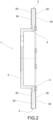
- reference numeral 1 globally denotes a brake disc according to the present invention.
- the brake disc 1 comprises a braking band 2, provided with two opposite braking surfaces 2a and 2b, each of which at least partially defines one of the two main faces of the disc.
- the braking band 2 is made of gray cast iron or steel.
- the braking band 2 is made of gray cast iron.
- the entire disc is made of gray cast iron.
- reference will therefore be made to a gray cast iron disc, without however excluding the possibility that it is made of steel.
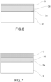
- the disc 1 is provided with a base layer 30 which covers at least one of the two braking surfaces 2a, 2b of the braking band and is preferably made in direct contact with said braking surfaces 2a, 2b.
- such base layer 30 is composed of steel having a nickel content lower than or at most equal to 15%.
- such base layer 30 is totally nickel-free. This allows limiting, if not even avoiding, the dispersion of nickel particles during the life of the brake disc 1.
- the content of carbon C of the steel of the base layer is comprised between 0.16 and 0.25%.
- the aforesaid composition allows a reduced percentage of any carbides included in the steel to be used, without reducing the hardness of any coating (described in more detail, later in the text).
- the chromium (Cr) content in the steel of the base layer 30 is comprised between 11% and 14%, extremes included.
- the base layer 30 also is composed of one or more carbides included in the nickel-free steel. Such inclusion is obtained by means of techniques known to those skilled in the art of inclusion of carbides in steel, for example the carbides are dissolved in the alloy.
- the one or more carbides included comprise at least one carbide selected from the group comprising: tungsten carbide (WC), chromium carbide (preferably, but not limited to, Cr3C2), Niobium carbide (NbC), titanium carbide (TiC). It is clear that more than one carbide selected from the aforementioned group or all the carbides present in the present group may also be present.
- the one or more carbides included comprise at least one carbide selected from the group comprising: tungsten carbide (WC), chromium carbide (e.g., Cr3C2), Niobium carbide (NbC), titanium carbide (TiC).
- tungsten carbide WC
- Cr3C2 chromium carbide
- NbC Niobium carbide
- TiC titanium carbide
- the brake disc 1 comprises a protective surface coating 3 which covers the base layer 30 at least on the side of one of the two braking surfaces 2a, 2b of the braking band.
- Such protective surface coating 3 is arranged on one side of the base layer 30 which does not face towards the braking surface 2a, 2b.
- the surface protective coating 3 is composed of at least one carbide or more carbides in particle form which may be deposited by the Thermal Spray deposition technique, for example by the HVOF (High Velocity Oxy-Fuel) technique, or by the HVAF (High Velocity Air Fuel) technique or by the APS (Atmosphere plasma spray) technique or by the Cold Spray deposition technique, for example by the KM (Kinetic Metallization) technique, or by the deposition technique using a laser beam, for example by the LMD (Laser Metal Deposition) technique, or by HSLC - high speed laser cladding technique, or by EHLA - Extreme High Speed Laser Application technique, or by TSC - Top Speed Cladding technique.
- HVOF High Velocity Oxy-Fuel
- HVAF High Velocity Air Fuel
- APS Admosphere plasma spray
- the Cold Spray deposition technique for example by the KM (Kinetic Metallization) technique
- the deposition technique using a laser beam for example by
- the surface protective coating 3 is therefore obtained by depositing directly on the disc 1 one or more carbides in particle form also by the HVOF technique, or by the HVAF (High Velocity Air Fuel) technique or by the KM (Kinetic Metallization) technique, preferably tungsten carbide (WC) or chromium carbide (for example, Cr3C2) or niobium carbide (NbC) or titanium carbide (TiC).
- HVOF High Velocity Air Fuel
- KM Kinetic Metallization
- the surface protective coating 3 is composed of steel having a nickel content lower than or at most equal to 15% or lower or at most equal to 7.5%, or lower or at most equal at 5%, or even more preferably totally free from nickel, and of one or more carbides included in the steel.
- the base layer 30 in nickel-free steel and above a protective surface coating 3 composed of the aforementioned steel and one or more carbides included in the steel are joined above the cast iron band in the order indicated.
- carbides deposited on the surface or included in the steel substantially or totally without nickel allows imparting mechanical strength and wear resistance, so as to compensate for the scarcity or total lack of nickel inside the steel.
- the surface protective coating 3 is composed of one or more of the following carbides: tungsten carbide (WC), niobium carbide (NbC), chromium carbide (for example, Cr3C2), titanium carbide (TiC).
- such protective surface coating 3 is obtained by depositing on the base layer 30 one or more of the aforementioned carbides in particle form by the Thermal Spray deposition technique, for example by the HVOF (High Velocity Oxy-Fuel) technique, or by the HVAF (High Velocity Air Fuel) technique or by the APS (Atmosphere plasma spray) technique or by the Cold Spray deposition technique, for example by the KM (Kinetic Metallization) technique, or by the deposition technique using a laser beam, for example by the LMD (Laser Metal Deposition) technique, or by HSLC - high speed laser cladding technique, or by EHLA - Extreme High Speed Laser Application technique, or by TSC - Top Speed Cladding technique.
- the Thermal Spray deposition technique for example by the HVOF (High Velocity Oxy-Fuel) technique, or by the HVAF (High Velocity Air Fuel) technique or by the APS (Atmosphere plasma spray) technique or by the Cold Spray deposition technique, for example
- the surface protective coating 3 is composed of chromium carbide (for example, Cr3C2) and titanium carbide (TiC).
- the surface protective coating 3 is composed of at least one metal oxide or a mixture of metal oxides or a mixture of metals and ceramic materials, preferably a mixture of aluminum oxides Al2O3, or a mixture of Al2O3 and intermetallic matrix Fe-Cr, for example Fe28Cr.
- the surface protective coating 3 is composed of one or more of the following carbides: tungsten carbide (WC), niobium carbide (NbC), chromium carbide (for example, Cr3C2), titanium (TiC), mixed with a mixture of metal oxides or mixed with a mixture of metals and ceramic materials, preferably with a mixture of aluminum oxides Al2O3, or a mixture of Al2O3 and intermetallic matrix Fe-Cr, for example Fe28Cr.
- carbides tungsten carbide (WC), niobium carbide (NbC), chromium carbide (for example, Cr3C2), titanium (TiC), mixed with a mixture of metal oxides or mixed with a mixture of metals and ceramic materials, preferably with a mixture of aluminum oxides Al2O3, or a mixture of Al2O3 and intermetallic matrix Fe-Cr, for example Fe28Cr.
- oxides or mixtures of oxides, or the metals or mixtures of metals and ceramic materials, or the mixtures of carbides and metal oxides described above are preferably deposited by the same deposition techniques of the carbides in particle form described above and in the present discussion.
- the surface protective coating 3 has a thickness comprised between 30 ⁇ m and 150 ⁇ m, and preferably between 50 ⁇ m and 90 ⁇ m.
- the steel of the base layer 30 comprises between 10% and 20% of chromium (Cr).
- the steel of the base layer 30 comprises at least 15% chromium (Cr), even more preferably between 16% and 18% chromium.
- the steel of the base layer 30 comprises at most 5% manganese (Mn) , even more preferably, the manganese content is between 0.5% and 5%, extremes included, so as to at least partially compensate for the lack of the properties of the steel alloy generally imparted by the presence of nickel, increasing the mechanical strength.
- Mn manganese
- the steel of the base layer 30 is composed of 10 to 20% of Chromium (Cr) by weight, preferably between 16% to 18% of chromium (Cr) by weight, at most 1.5% by weight of silicon (Si), at most 2% by weight of manganese (Mn) , at most 0.03% by weight of carbon (C) and for the balance iron (Fe), i.e. for the remaining percentage by weight of iron.
- the base layer 30 has a thickness comprised between 20 ⁇ m and 300 ⁇ m, and preferably equal to 90 ⁇ m.
- the steel of the base layer 30 has a molybdenum content between 0.5% and 10%, even more preferably between 0.5% and 4.5%, extremes included and a manganese content between 0.5% and 5%.
- the presence of molybdenum and manganese in the above percentages allows adequate resistance to corrosion and at the same time adequate mechanical resistance to be obtained.
- an intermediate layer 300 of steel comprising nickel, preferably with a nickel content higher than 5% in the case in which the base layer 30 is totally free from nickel, or, even more preferably with a nickel content of at least 5%, and even more preferably with a nickel content of at least 5% and less than 15%.
- the intermediate layer 300 comprises a steel with a nickel content of at most 15% or equal to 15%.
- the intermediate layer 300 comprises a steel with a nickel content of at most 7.5% or equal to 7.5%.
- an intermediate layer 300 of nickel- free steel is interposed between the base layer 30 and at least one of the two braking surfaces 2a, 2b of the braking band.
- the intermediate layer 300 comprises a nickel-free steel composed of 10% to 15% of chromium (Cr), at most 1% of silicon (Si), at most 4% of manganese (Mn), from 0.16% to 0.5% of carbon (C) and for the balance iron (Fe).
- the carbon (C) content is comprised between 0.16% and 0.25%.
- the presence of the intermediate layer 300 allows a disc with adequate mechanical features to be obtained, but at the same time with a reduced environmental impact, by virtue of the presence of the base layer 30.
- the intermediate layer 300 comprises steel composed of 10% to 15% of chromium (Cr), at most 1% of silicon (Si), at most 4% of manganese (Mn), from 0.16% to 0.5% of carbon (C) and for the balance iron (Fe).
- the carbon (C) content of the steel of the intermediate layer 300 is comprised between 0.16% and 0.25%, extremes included.
- the surface protective coating 3 comprises steel composed of 10% to 15% of chromium (Cr), at most 1% of silicon (Si), at most 4% of manganese (Mn), between 0.16% and 0.5% of carbon (C) and for the balance iron (Fe), preferably without nickel.
- the carbon (C) content of the steel of the surface protective coating is comprised between 0.16% and 0.25%, extremes included.
- an auxiliary layer of ferritic-nitrocarburization or an auxiliary ferroalumination layer is interposed between one of the two braking surfaces 2a, 2b of the braking band and the base layer 30, or between one of the two braking surfaces 2a, 2b of the braking band and the intermediate layer 300, or between the base layer 30 and the surface protective coating 3, or between the intermediate layer 300 and the base layer 30.
- an auxiliary layer of ferritic-nitrocarburization and an auxiliary ferroalumination layer is interposed between one of the two braking surfaces 2a, 2b of the braking band and the base layer 30, or between one of the two braking surfaces 2a, 2b of the braking band and the intermediate layer 300, or between the base layer 30 and the surface protective coating 3, or between the intermediate layer 300 and the base layer 30.
- the brake disc 1 will now be described contextually to the method according to the present invention.
- the brake disc 1 is preferably, but not necessarily, made by the method according to the invention which will now be described.
- a general embodiment of the method according to the invention comprises the following operating steps:
- step a1) provides for depositing an intermediate layer 300 composed of nickel-free steel and from 10% to 15% of chromium (Cr), at most 1% of silicon (Si), at most 4% of manganese (Mn) , from 0.16% to 0.5% of carbon (C), preferably from 0.16% to 0.25% of carbon (C), extremes included, and for the balance of iron (Fe).
- Cr chromium
- Si silicon
- Mn manganese
- C carbon
- C preferably from 0.16% to 0.25% of carbon
- extremes included and for the balance of iron (Fe).
- a general embodiment of the method according to the invention comprises the following operating steps:
- the method preferably provides for the further steps which will be described below.
- step c) the tungsten carbide (WC) or the niobium carbide (NbC) or the titanium carbide (TiC) or possibly the chromium carbide is dispersed in a metal matrix.
- the material in particle form is composed of chromium carbide and titanium carbide.
- the brake disc is arranged with a portion suitable for fixing the disc to a vehicle, composed of an annular portion 4 arranged centrally to the disc 1 and concentric to the braking band 2.
- the fixing portion 4 supports the connecting element 5 to the wheel hub (i.e. the bell).
- the bell may be made in one piece with the annular fixing portion (as illustrated in the accompanying figures) or it may be made separately and, therefore, fixed through suitable connecting elements to the fixing portion.
- the annular fixing portion 4 may be made of the same material as the braking band, that is, of gray cast iron, or of another suitable material.
- the bell 5 may also be made of gray cast iron or of another suitable material.
- the whole disc i.e. braking band, fixing portion and bell
- the whole disc i.e. braking band, fixing portion and bell
- the braking band 2 is made by casting.
- the fixing portion and/or the bell may be made by casting.
- the annular fixing portion may be made in a single body with the braking band (as illustrated in the accompanying figures) or be made as a separate body, mechanically connected to the braking band.
- HVOF HVAF or KM
- LMD LMD or HSLC
- HVOF High Velocity Oxygen Fuel
- a powder spray deposition technique which uses a spray device provided with a mixing and combustion chamber and a spray nozzle.
- the chamber is supplied with oxygen and fuel.
- the hot combustion gas which forms at pressures close to 1 MPA passes through the converging-diverging nozzle into the powdered material reaching hypersonic speeds (i.e. higher than MACH 1).
- the powder material to be deposited is injected into the hot gas stream, where it melts rapidly and is accelerated to speeds of the order of 1000 m/s. Once impacted on the deposition surface, the molten material cools rapidly and due to the impact with high kinetic energy it forms a very dense and compact structure.
- the High Velocity Air Fuel (HVAF) deposition technique is similar to the HVOF technique. The difference is that in the HVAF technique the combustion chamber is fed with air instead of oxygen. The temperatures involved are therefore lower than those of the HVOF. This allows for greater control of the thermal alteration of the coating.
- HVAF High Velocity Air Fuel
- the KM (Kinetic Metallization) deposition technique is a solid-state deposition process in which metal powders are sprayed through a two-phase sonic deposition nozzle which accelerates and triboelectrically charges metal particles within an inert gas stream. Thermal energy is expected to be supplied to the transport stream. The process transforms the potential energy of the compressed inert gas stream and the thermal energy supplied into the kinetic energy of the powders. Once accelerated to high speed and electrically charged, the particles are directed against the deposition surface. The high-speed collision of the metal particles with this surface causes a large deformation of the particles (approximately 80% in the direction normal to impact). This deformation results in a huge increase in the surface area of the particles. Upon impact, the effect is therefore intimate contact between the particles and the deposition surface, which leads to the formation of metal bonds and a coating having a very dense and compact structure.
- the combination of the HVOF or HVAF or KM or LMD or HSLC deposition technique and the chemical components used for the formation of the base layer 30 and the surface protective coating 3, allows both high bond strength on the lower material on which they are deposited and the deposition of powders with high carbide content to be obtained.
- the base layer 30 and the protective surface coating 3 cover at least one of the two braking surfaces of the braking band.
- coating will refer to both the set given by the base layer 30 and the protective surface coating 3, and to the base layer 30 alone, in the variant which does not provide for the surface protective coating 3, but which provides for the inclusion of carbides in the base layer 3.
- the disc 1 is provided with a coating 3, 30 which covers both the braking surfaces 2a and 2b of the braking band 2.
- the coating 3, 30 may cover only the braking band, on a single braking surface or on both.
- the coating 3, 30 may also extend to other parts of the disc 1 such as the annular fixing portion 4 and the bell 5, up to cover the entire surface of the disc 1.
- the coating 3, 30 may cover - in addition to the braking band - only the fixing portion or only the bell. The choice is dictated by essentially aesthetic reasons, in order to have a homogeneous coloring and/or finish on the whole disc or between some portions thereof.
- the deposition of the particulate material for the formation of the coating 3, 30 may be carried out in a differentiated manner on the surface of the disc at least in terms of thickness of the coating.
- the coating 3, 30 may be made with the same thickness in the two opposite braking surfaces.
- Alternative solutions may be provided in which the coating 3, 30 is made by differentiating the different thicknesses between the two braking surfaces of the braking band.
- the step b) of depositing the base layer 30 provides for depositing a composition in particle form composed of steel having a nickel content of at most 15% or at most 7.5% or at most 5% or totally nickel-free steel, by laser deposition technique, preferably LMD (Laser Metal Deposition) or EHLA (Extreme High-Speed Laser Material Deposition), or by Thermal Spray deposition technique, or by the Cold Spray deposition technique.
- laser deposition technique preferably LMD (Laser Metal Deposition) or EHLA (Extreme High-Speed Laser Material Deposition)
- Thermal Spray deposition technique or by the Cold Spray deposition technique.
- the composition in particle form further comprises carbides mixed in a percentage not exceeding 50% by weight of the total particulate composition.
- the composition in particle form in addition to steel, also includes metal oxides or a mixture of metals and ceramic materials, preferably a mixture of aluminum oxides Al2O3, or a mixture of Al2O3 and intermetallic matrix Fe-Cr, for example Fe28Cr.
- the composition in particle form in addition to steel, also includes metal oxides or a mixture of metals and ceramic materials, preferably a mixture of aluminum oxides Al2O3, or a mixture of Al2O3 and intermetallic matrix Fe-Cr, for example Fe28Cr, and also one or more carbides selected from the group comprising: tungsten carbide (WC), niobium carbide (NbC), titanium carbide (TiC), chromium carbide.
- WC tungsten carbide
- NbC niobium carbide
- TiC titanium carbide
- chromium carbide chromium carbide
- the base layer 30 comprises a mixture of steel and metal oxides described above, or, in another variant, a mixture of steel and metal oxides and carbides described above.
- the step a1) of depositing the intermediate layer 300 provides for depositing a composition in particle form composed of steel having a nickel content between 5% and 15%, by means of a laser deposition technique, preferably LMD (Laser Metal Deposition) or EHLA (Extreme High-Speed Laser Material Deposition), or by the Thermal Spray deposition technique, or by the Cold Spray deposition technique.
- a laser deposition technique preferably LMD (Laser Metal Deposition) or EHLA (Extreme High-Speed Laser Material Deposition)
- the Thermal Spray deposition technique or by the Cold Spray deposition technique.
- the step e1) is provided of depositing an auxiliary layer of ferritic-nitrocarburization between one of the two braking surfaces 2a, 2b of the braking band and the base layer 30, and/or between one of the two braking surfaces 2a, 2b of the braking band and the intermediate layer 300, and/or between the base layer 30 and the protective surface coating 3, and/or between the intermediate layer 300 and the base layer 30.
- the method comprises the step e2) of depositing an auxiliary ferroalumination layer between one of the two braking surfaces 2a, 2b of the braking band and the base layer 30, and/or between one of the two braking surfaces 2a, 2b of the braking band and the intermediate layer 300, and/or between the base layer 30 and the protective surface coating 3, and/or between the intermediate layer 300 and the base layer 30.
- the ferroalumination step e2) comprises the steps of:
- the layer of ferroaluminum intermetallic compounds exposed on the surface imparts a superior resistance to corrosion and wear at said predetermined surface region to the braking band 2 made of cast iron or steel.
- the layer of ferroaluminum intermetallic compounds comprises FeAl3 as the prevailing phase of the ferroaluminum intermetallic compounds.
- the predefined temperature at which the molten aluminum is maintained is not higher than 750 °C, and is preferably between 690 °C and 710 °C, and even more preferably equal to 700 °C.
- the predefined period of immersion time is determined according to the thickness to be obtained for said layer of intermetallic compounds, at the same temperature of the molten aluminum said thickness increasing as the immersion time increases, with the same immersion time, said thickness increasing as the temperature of the molten aluminum increases, preferably said predefined immersion time being between 5 and 60 min, and even more preferably equal to 30 min.
- the method comprises a step f) of decarburizing said predefined surface region of said braking band 2 up to a predefined depth.
- the surface decarburization therefore allows avoiding (or at least significantly reducing) the formation of iron carbide, leading to the formation of a layer of intermetallic compounds more resistant to corrosion and less subject to cracking.
- the decarburization of said at least one predefined surface region is carried out by means of an electrolytic process.
- said electrolytic process is carried out by immersing the predefined surface region of said braking band in a bath of molten salts and applying an electric potential difference between the bath and the braking band.
- the braking band is connected to a positive pole (cathode), while the aforementioned bath of molten salts is connected to a negative pole (anode).
- Carbon particularly in the form of graphite flakes, is oxidized to carbon dioxide by the release of electrons and atomic oxygen released at the anode. Carbon reacts primarily with oxygen and is eventually bound as carbon dioxide.
- the oxidation of the surface of the braking band induced by the electrolytic process is not limited to the carbon present therein, but also extends to the metal matrix of the cast iron (iron), causing the formation of a surface film of metal oxide. Reversing the polarity causes the reduction of the surface film of metal oxide which is thus returned to the original metallic state.
- the aforementioned electrolytic process may therefore provide that, after a predefined period of time in which the surface of the braking band has been connected to the cathode to oxidize the carbon, the polarity is reversed so as to return the metal oxide film to its original metallic state.
- the decarburization depth is controlled by adjusting the duration of the electrolytic process, possibly divided into different polarity inversion cycles.
- the duration of the decarburization process oxidation phase of the braking band; connection to the cathode
- the decarburization depth increases, all other conditions being equal.
- the decarburization may be carried out with alternative processes to the electrolytic process described above, for example by means of a laser treatment or a chemical treatment.
- the growth thickness of the intermetallic compound layer is mainly influenced by the temperature of the molten aluminum and the immersion time in the molten aluminum.
- a further factor affecting the thickness of the intermetallic compound layer is the silicon content in the molten aluminum.
- the silicon content in the molten aluminum The higher the weight content of silicon in the molten aluminum, the lower the thickness of the intermetallic compound layer under the same conditions.
- the molten aluminum has a silicon content lower than 1% by weight.
- the molten aluminum has an impurity content not higher than 1% by weight.
- aluminum with a maximum purity of 99.7% by weight may be used, with the following impurities (% by weight): Si ⁇ 0.30%; Fe ⁇ 0.18%; Sr ⁇ 0.0010%; Na ⁇ 0.0025%; Li ⁇ 0.0005%; Ca ⁇ 0.0020%; P ⁇ 0.0020; Sn ⁇ 0.020 %.
- the excessive solubility of iron in molten aluminum may totally or partially cancel the beneficial effects of the surface decarburization of the braking surface.
- the step b1) of immersion in a bath of molten aluminum in which iron has been dissolved may be carried out.
- the formation of FeAl3 is kinematically promoted, so as to allow the intermetallic compounds to form at the decarburized layer.
- the iron content in solution in the aluminum bath is not higher than 5% by weight, and even more preferably it is comprised between 3% and 5%, and most preferably equal to 4% by weight to ensure a significant effect of slowing of the melting process of the iron of the cast iron in the aluminum.
- an aluminum bath having the following composition may be used: Al ⁇ 97%; Fe 3-5%; with the following impurities: Si ⁇ 0.30%; Fe ⁇ 0.18%; Sr ⁇ 0.0010%; Na ⁇ 0.0025%; Li ⁇ 0.0005%; Ca ⁇ 0.0020%; P ⁇ 0.0020; Sn ⁇ 0.020 %.
- step b1) of immersion is carried out in two sub-steps:
- the immersion time of said braking band in said first bath is less than the immersion time of said braking band in said second bath.
- the immersion of said braking band in said first bath is continued for a period of time as short as possible, but sufficient to obtain on said predefined surface region an initial layer composed of ferroaluminum intermetallic compounds having a thickness not exceeding at 10 ⁇ m.
- the immersion time in said first bath is between 3 and 5 minutes if the first bath is at a temperature of about 700 °C. As the bath temperature increases, the immersion time must decrease.
- said thickness increases as the immersion time increases and for the same immersion time, said thickness increases as the temperature of the second bath increases.
- both said first bath of molten aluminum and said second bath have an impurity content not higher than 1% by weight.
- said two molten aluminum baths have a silicon content lower than 1% by weight.
- the iron content in solution in the second aluminum bath is not higher than 5% by weight (at 700 °C the solubility limit of iron in aluminum is 4% by weight; aluminum saturated with iron), and even more preferably it is comprised between 3% and 5%, and most preferably it is equal to 4% by weight.
- the iron content should not be less than 3% to ensure a significant slowing effect of the melting process of the iron of the cast iron in the aluminum.
- both said first bath and said second bath are maintained at a temperature lower than 680 °C, preferably not higher than 750 °C, more preferably between 690 °C and 710 °C, and even more preferably equal to 700 °C.
- the method may comprise a step of surface pretreatment of the braking band which is carried out before said immersion step e21) at least at said predefined surface region.
- said surface pretreatment step comprises lapping, degreasing, sandblasting and/or chemical removal of the surface oxides.
- the method comprises a step of removing a surface layer of oxides from the molten aluminum bath before said immersion step e21).
- This step of removal of the surface oxides is carried out both in the case in which immersion in a single bath is contemplated, and in the case in which immersion is contemplated in two successive steps in a first and in a second bath.
- the step of removing the aluminum remaining adhered to said braking band after the extraction is carried out in two sub-steps:
- the method comprises a quenching step of said braking band carried out between said first removal sub-step and said second removal sub-step.
- said first removal sub-step may be carried out by mechanical shaving of the still liquid aluminum.
- said second removal sub-step may be carried out by chemical removal of the solidified aluminum not removed mechanically.
- the aforementioned chemical removal is carried out by exposing the aluminum to ferric chloride for at least 4 minutes so as to cause the following reaction: Al+ FeCl3 -> AlCl3 + Fe
- ferroalumination therefore allow a braking band, and therefore a brake disc, to be obtained with increased resistance to wear and corrosion.
- the layer of ferroaluminum intermetallic compounds may comprise a plurality of intermetallic compounds between iron and aluminum, in particular Fe3Al, FeAl, FeAl2, FeAl3, Fe2Al5.
- the prevailing intermetallic phase is FeAl3 as it is thermodynamically more stable.
- the method provides for depositing an auxiliary ferritic-nitrocarburization and an auxiliary ferroalumination layer between one of the two braking surfaces 2a, 2b of the braking band and the base layer 30, and/or between one of the two braking surfaces 2a, 2b of the braking band and the intermediate layer 300, and/or between the base layer 30 and the protective surface coating 3, and/or between the intermediate layer 300 and the base layer 30.
- the brake disc according to the invention allows the drawbacks of the prior art to be overcome.
- the brake disc 1 according to the invention is substantially not subject to the production and release of nickel particles during operation.
- a protective surface coating 3 which includes or is coated with carbides, allows both the wear resistance properties to be improved, also compensating for the lack of nickel in the steel of the base layer, and adequate and increased mechanical strength to be provided.
- the base layer 30 composed of totally nickel-free steel and 10% to 15% chromium (Cr), at most 1% of silicon (Si), at most 4% of manganese (Mn), from 0.16% to 0.5% of carbon (C), preferably from 0.16% to 0.25% of carbon (C), and for the balance of iron (Fe), allows a martensitic steel without nickel to be made with less brittleness during use at high temperatures and at the same time an adequate anticorrosive coating.
- Cr chromium
- Si silicon
- Mn manganese
- C carbon
- C preferably from 0.16% to 0.25% of carbon
- Fe iron
- the base layer 30, in fact, assumes an elastic behavior which allows the stresses imparted to the disc to be attenuated at least in part when in use.
- the base layer 30 therefore operates as a sort of shock absorber or cushion between the disc and the protective surface coating 3. In this way, a direct transmission of stresses between the two parts is avoided, thus also reducing the risk of initiation of cracks in the protective surface coating 3.
Landscapes
- Chemical & Material Sciences (AREA)
- Engineering & Computer Science (AREA)
- Mechanical Engineering (AREA)
- Organic Chemistry (AREA)
- Chemical Kinetics & Catalysis (AREA)
- Materials Engineering (AREA)
- Metallurgy (AREA)
- General Engineering & Computer Science (AREA)
- Plasma & Fusion (AREA)
- Physics & Mathematics (AREA)
- Inorganic Chemistry (AREA)
- Braking Arrangements (AREA)
- Coating By Spraying Or Casting (AREA)
- Other Surface Treatments For Metallic Materials (AREA)
- Coating With Molten Metal (AREA)
Claims (15)
- Bremsscheibe (1) für eine Scheibenbremse, umfassend ein Bremsband (2), welche mit zwei entgegengesetzten Bremsflächen (2a, 2b) bereitgestellt ist, von welchen jede wenigstens teilweise eine der zwei Hauptflächen der Scheibe (1) definiert, wobei das Bremsband (2) aus einem Grauguss oder Stahl gefertigt ist,dadurch gekennzeichnet, dass die Scheibe mit einer Grundschicht (30) bereitgestellt ist, welche wenigstens eine der zwei Bremsflächen (2a, 2b) des Bremsbands bedeckt, wobei die Grundschicht (30) aus Stahl, welcher komplett frei von Nickel ist, und aus einem oder mehreren Karbiden zusammengesetzt ist, welche in dem nickelfreien Stahl umfasst sind,und dadurch, dass eine Zwischenschicht (300), welche aus einem nickelfreien Stahl zusammengesetzt ist, zwischen der Grundschicht (30) und wenigstens einer der zwei Bremsflächen (2a, 2b) des Bremsbands (2) eingefügt ist.
- Bremsscheibe (1) für eine Scheibenbremse nach Anspruch 1, wobei das eine oder die mehreren in der Grundschicht (30) umfassten Karbide wenigstens ein Karbid umfassen, welches ausgewählt ist aus der Gruppe, umfassend: Wolframkarbid (WC), Chromkarbid, Niobkarbid (NbC), Titankarbid (TiC).
- Bremsscheibe (1) für eine Scheibenbremse nach einem der vorhergehenden Ansprüche, welche eine schützende Flächenbeschichtung (3) umfasst, welche die Grundschicht (30) wenigstens an der Seite einer der zwei Bremsflächen (2a, 2b) des Bremsbands bedeckt, wobei die schützende Flächenbeschichtung (3) an einer Seite der Grundschicht (30) angeordnet ist, welche der einen der zwei Bremsflächen (2a, 2b) nicht zugewandt ist, wobei die schützende Flächenbeschichtung (3) aus einem oder mehreren Karbiden in Partikelform zusammengesetzt ist, welche durch eine Thermal-Spray-Anlagerungstechnik angelagert sind, zum Beispiel durch die HVOF (High Velocity Oxy Fuel) Technik oder durch die HVAF (High Velocity Air Fuel) Technik oder durch die APS (Atmosphere Plasma Spray) Technik oder durch eine Cold-Spray-Anlagerungstechnik, zum Beispiel durch die KM (Kinetic Metallization) Technik oder durch eine Laserstrahlanlagerungstechnik, zum Beispiel die LMD (Laser Metal Deposition) oder die HSLC (High Speed Laser Cladding) Technik oder die EHLA (Extrem High Speed Laser Application) Technik oder die TSC (Top Speed Cladding) Technik.
- Bremsscheibe (1) für eine Scheibenbremse nach Anspruch 3, wobei das eine oder die mehreren Karbide in Partikelform Wolframkarbid (WC) oder Chromkarbid oder Niobkarbid (NbC) oder Titankarbid (TiC) umfassen.
- Bremsscheibe (1) für eine Scheibenbremse nach Anspruch 4, wobei die Karbide in Partikelform aus Chromkarbid und Titankarbid zusammengesetzt sind.
- Scheibe nach einem der vorhergehenden Ansprüche, wobei der Stahl der Grundschicht (30) wenigstens 15 % Chrom (Cr) umfasst.
- Scheibe nach einem der Ansprüche 1 bis 6, wobei der Stahl der Grundschicht (30) zwischen 10 % und 20 % Chrom (Cr) umfasst, einschließlich der Extreme.
- Scheibe nach einem der vorhergehenden Ansprüche, wobei der Stahl der Grundschicht (30) einen Gehalt von Molybdän, welcher zwischen 0,5 % und 10 % umfasst ist, einschließlich der Extreme, und einen Gehalt von Mangan zwischen 0,5 % und 7 % aufweist.
- Scheibe nach einem der vorhergehenden Ansprüche, wobei der Stahl der Grundschicht (30) zusammengesetzt ist aus 10 % bis 20 % Chrom (Cr), höchstens 1,5 % Silizium (Si), höchstens 2 % Mangan (Mn), höchstens 0,03 % Kohlenstoff (C) und für den Restbetrag Eisen (Fe).
- Scheibe nach einem der vorhergehenden Ansprüche, wobei die Grundschicht (30) eine Dicke aufweist, welche zwischen 20 µm und 300 µm umfasst ist, bevorzugt gleich 90 µm ist.
- Verfahren zum Fertigen einer Bremsscheibe, umfassend die folgenden Betriebsschritte:a) Vorbereiten einer Bremsscheibe (1), umfassend ein Bremsband (2), welches mit zwei entgegengesetzten Bremsflächen (2a, 2b) bereitgestellt ist, von welchen jede wenigstens teilweise eine der zwei Hauptflächen der Scheibe definiert, wobei das Bremsband aus einem Grauguss oder Stahl gefertigt ist,
a1) nach Schritt a), Anlagern einer Zwischenschicht (300), welche aus einem nickelfreien Stahl zusammengesetzt ist, an wenigstens einer der zwei entgegengesetzten Bremsflächen (2a, 2b);b) nach Schritt a1), Anlagern einer Grundschicht (30), welche aus einem Stahl zusammengesetzt ist, welcher komplett frei von Nickel ist. - Verfahren nach Anspruch 11, wobei der Schritt b) des Anlagerns der Grundschicht (30) ein Anlagern einer Zusammensetzung in Partikelform umfasst, welche aus nickelfreiem Stahl zusammengesetzt ist, mit Hilfe einer Laseranlagerungstechnik, bevorzugt Laser Metal Deposition oder Extreme High-Speed Laser Material Deposition oder mit Hilfe einer Thermal Spray Anlagerungstechnik oder mit Hilfe einer Cold Spray Anlagerungstechnik.
- Verfahren nach Anspruch 12, wobei, in Schritt b), die Zusammensetzung in Partikelform ferner Karbide umfasst, welche in einem Anteil gemischt sind, welcher 50 Gew.-% der gesamten Partikelzusammensetzung nicht überschreitet.
- Verfahren nach einem der Ansprüche 11 oder 12 oder 13, ferner umfassend den Schritt c) eines Anlagerns über der Grundschicht (30) eines Materials in Partikelform, welches aus Wolframkarbid (WC) oder Niobkarbid (NbC) oder Titankarbid (TiC) oder Chromkarbid zusammengesetzt ist, durch eine Thermal-Spray-Anlagerungstechnik, zum Beispiel durch die HVOF (High Velocity Oxy Fuel) Technik, die HVAF (High Velocity Air Fuel) Technik, die APS (Atmosphere Plasma Spray) Technik oder eine Cold-Spray-Anlagerungstechnik, zum Beispiel durch die KM (Kinetic Metallization) Technik oder durch eine Laserstrahlanlagerungstechnik, zum Beispiel durch die LMD (Laser Metal Deposition) Technik oder durch die HSLC (High Speed Laser Cladding) Technik oder durch die EHLA (Extrem High Speed Laser Application) Technik oder durch die TSC (Top Speed Cladding) Technik, wobei eine schützende Flächenbeschichtung (3) gebildet wird, welche die Grundschicht (30) bedeckt, bevorzugt wenigstens für die gesamte Fläche einer der zwei Bremsflächen (2a, 2b) des Bremsbands.
- Verfahren nach einem der Ansprüche 12 bis 14, ferner umfassend den Schritt e1) eines Anlagerns einer Hilfsschicht eines ferritischen Nitrocarburierens zwischen einer der zwei Bremsflächen (2a, 2b) des Bremsbands und der Grundschicht (30), und/oder zwischen einer der zwei Bremsflächen (2a, 2b) des Bremsbands und der Zwischenschicht (300), und/oder zwischen der Grundschicht (30) und der schützenden Flächenbeschichtung (3), und/oder zwischen der Zwischenschicht (300) und der Grundschicht (30), oder umfassend den Schritt e2) eines Anlagerns einer Hilfsferroaluminierungsschicht zwischen einer der zwei Bremsflächen (2a, 2b) des Bremsbands und der Grundschicht (30), und/oder zwischen einer der zwei Bremsflächen (2a, 2b) des Bremsbands und der Zwischenschicht (300), und/oder zwischen der Grundschicht (30) und der schützenden Flächenbeschichtung (3), und/oder zwischen der Zwischenschicht (300) und der Grundschicht (30),
wobei der Ferroaluminierungsschritt e2) die folgenden Schritte umfasst:e21) wenigstens teilweises Eintauchen des Bremsbands (2) in geschmolzenes Aluminium, welches bei einer vorbestimmten Temperatur gehalten wird, sodass das geschmolzene Aluminium wenigstens einen vorbestimmten Flächenbereich des Bremsbands (2) bedeckt, wobei das Eintauchen für eine vorbestimmte Zeitperiode hingezogen wird, um die Diffusion von Aluminiumatomen in die Flächenmikrostruktur des Graugusses oder des Stahls mit der folgenden Bildung von intermetallischen Ferroaluminium-Verbindungen in einer Flächenschicht des Bremsbands (2) zu ermöglichen, wobei somit eine Schicht erzeugt wird, welche intermetallische Ferroaluminium-Verbindungen in dem vorbestimmten Flächenbereich des Bremsbands umfasst;e22) Entnehmen des Bremsbands aus dem flüssigen Aluminium;e23) Entnehmen des Aluminiums, welches nach der Entnahme an dem Bremsband zurückbleibt, um die Schicht intermetallischer Ferroaluminium-Verbindungen an der Fläche freizulegen, wobei die Schicht intermetallischer Ferroaluminium-Verbindungen, welche an der Fläche freigesetzt ist, dem Bremsband, welches aus Grauguss oder Stahl gefertigt ist, einen verbesserten Widerstand gegen Korrosion und Abnutzung an dem vorbestimmten Flächenbereich verleiht.
Applications Claiming Priority (2)
| Application Number | Priority Date | Filing Date | Title |
|---|---|---|---|
| IT102020000032417A IT202000032417A1 (it) | 2020-12-24 | 2020-12-24 | Disco freno a doppio strato in acciaio senza nickel e metodo di realizzazione |
| PCT/IB2021/062238 WO2022137191A1 (en) | 2020-12-24 | 2021-12-23 | Double-layer brake disc in nickel-free steel and manufacturing method |
Publications (2)
| Publication Number | Publication Date |
|---|---|
| EP4267864A1 EP4267864A1 (de) | 2023-11-01 |
| EP4267864B1 true EP4267864B1 (de) | 2025-03-12 |
Family
ID=74875184
Family Applications (1)
| Application Number | Title | Priority Date | Filing Date |
|---|---|---|---|
| EP21844409.9A Active EP4267864B1 (de) | 2020-12-24 | 2021-12-23 | Doppelschichtige bremsscheibe aus nickelfreiem stahl und herstellungsverfahren |
Country Status (13)
| Country | Link |
|---|---|
| US (1) | US20240044384A1 (de) |
| EP (1) | EP4267864B1 (de) |
| JP (1) | JP7901082B2 (de) |
| KR (1) | KR20230124674A (de) |
| CN (1) | CN116867984A (de) |
| AR (1) | AR124503A1 (de) |
| CA (1) | CA3206463A1 (de) |
| ES (1) | ES3036676T3 (de) |
| HU (1) | HUE071799T2 (de) |
| IT (1) | IT202000032417A1 (de) |
| MX (1) | MX2023007684A (de) |
| PL (1) | PL4267864T4 (de) |
| WO (1) | WO2022137191A1 (de) |
Families Citing this family (7)
| Publication number | Priority date | Publication date | Assignee | Title |
|---|---|---|---|---|
| IT202000032408A1 (it) * | 2020-12-24 | 2022-06-24 | Brembo Spa | Disco freno con strato in acciaio senza nickel e metodo di realizzazione |
| IT202000032399A1 (it) * | 2020-12-24 | 2022-06-24 | Brembo Spa | Disco freno con strato in acciaio a ridotto contenuto di nickel e metodo di realizzazione |
| DE102023118027B3 (de) | 2023-07-07 | 2024-07-18 | C4 Laser Technology GmbH | Hartstoffbeschichteter Bremskörper und Verfahren zur Herstellung hartstoffbeschichteter Bremskörper |
| DE102023207017B3 (de) | 2023-07-24 | 2024-10-02 | Volkswagen Aktiengesellschaft | Bremskörper für ein Kraftfahrzeug |
| WO2025141406A1 (en) * | 2023-12-29 | 2025-07-03 | Brembo S.P.A. | Disc for disc brakes and method for manufacturing a disc for disc brakes |
| WO2025141408A1 (en) * | 2023-12-29 | 2025-07-03 | Brembo S.P.A. | Disc for disc brakes and method for manufacturing a disc for disc brakes |
| EP4764246A1 (de) * | 2024-12-20 | 2026-06-24 | Brembo N.V. | Bremsscheibe für scheibenbremsen und verfahren zur herstellung einer bremsscheibe für scheibenbremsen |
Citations (26)
| Publication number | Priority date | Publication date | Assignee | Title |
|---|---|---|---|---|
| US4715486A (en) | 1980-09-03 | 1987-12-29 | International Standard Electric Corporation | Low-wear frictionally engaging device |
| DE60215655T2 (de) | 2001-06-01 | 2007-08-23 | Sumitomo Metal Industries, Ltd. | Martensitischer nichtrostender stahl |
| EP1336054B1 (de) | 2000-11-13 | 2008-09-03 | KNORR-BREMSE SYSTEME FÜR NUTZFAHRZEUGE GmbH | Bremsscheibe und verfahren zu deren herstellung |
| WO2010089048A1 (de) | 2009-02-09 | 2010-08-12 | Daimler Ag | Verfahren zur herstellung einer bremsscheibe |
| DE102011056307A1 (de) | 2011-12-13 | 2013-06-13 | Dr. Ing. H.C. F. Porsche Aktiengesellschaft | Bremsscheibe und Verfahren zum Herstellen derselben |
| DE102011089864A1 (de) | 2011-12-23 | 2013-06-27 | Robert Bosch Gmbh | Bremsscheibe |
| WO2014097187A2 (en) | 2012-12-21 | 2014-06-26 | Freni Brembo S.P.A. | Method of making a brake disc and brake disc for disc brakes |
| WO2014097186A1 (en) | 2012-12-21 | 2014-06-26 | Freni Brembo S.P.A. | A method of making a brake disc, brake disc for disc brake and a disc brake |
| WO2015007497A1 (de) | 2013-07-15 | 2015-01-22 | Ford Global Technologies, Llc | Verfahren zur herstellung einer bremsscheibe sowie bremsscheibe |
| US20150159710A1 (en) | 2013-12-06 | 2015-06-11 | GM Global Technology Operations LLC | Friction material and methods of making and using the same |
| DE102014006064A1 (de) | 2013-12-18 | 2015-06-18 | Daimler Ag | Beschichtetes Grauguss-Bauteil und Herstellungsverfahren |
| EP3034902A1 (de) | 2013-09-13 | 2016-06-22 | Railway Technical Research Institute | Bremsscheibe und verfahren zur herstellung davon |
| US20170016497A1 (en) | 2014-03-11 | 2017-01-19 | Daimler Ag | Brake Disc Coating Made from an Iron Alloy Composition and Method for the Production Thereof |
| WO2017046681A1 (en) | 2015-09-14 | 2017-03-23 | Freni Brembo S.P.A. | Method for manufacturing a brake disc and brake disc for disc brakes |
| US20170122392A1 (en) | 2014-06-14 | 2017-05-04 | Daimler Ag | Brake Disc for a Motor Vehicle |
| DE202018107169U1 (de) | 2018-12-14 | 2019-01-02 | Höganäs Ab | Beschichtung insbesondere für Bremsscheiben, Bremstrommeln und Kupplungsscheiben, Bremsscheibe für eine Scheibenbremse oder Bremstrommel für eine Trommelbremse oder Kupplungsscheibe für eine Kupplung, Scheibenbremse oder Trommelbremse oder Kupplung und Verwendung einer Beschichtung |
| WO2019021161A1 (en) | 2017-07-28 | 2019-01-31 | Freni Brembo S.P.A. | METHOD FOR MANUFACTURING BRAKE DISC AND BRAKE DISC FOR DISC BRAKE |
| DE102019210088A1 (de) | 2018-09-04 | 2020-03-05 | Ford Global Technologies, Llc | Bremsscheibe und Verfahren zum Herstellen einer Bremsscheibe |
| DE102019212844A1 (de) | 2018-09-04 | 2020-03-05 | Ford Global Technologies, Llc | Bremsscheibe und Verfahren zum Herstellen einer Bremsscheibe |
| EP3620546A2 (de) | 2018-09-04 | 2020-03-11 | Ford Global Technologies, LLC | Bremsscheibe und verfahren zum herstellen einer bremsscheibe |
| WO2020128600A1 (fr) | 2018-12-21 | 2020-06-25 | Aperam | Disque de frein pour véhicule et son procédé de fabrication, dispositif de freinage le comportant et véhicule équipé d'un tel dispositif |
| DE102019207291A1 (de) | 2019-05-18 | 2020-11-19 | Robert Bosch Gmbh | Reibbremskörper für eine Reibbremse, Reibbremse und Verfahren zur Herstellung |
| DE102019208411A1 (de) | 2019-06-08 | 2020-12-10 | Robert Bosch Gmbh | Reibbremskörper für eine Reibbremse eines Kraftfahrzeugs, Reibbremse und Verfahren zur Herstellung eines Reibbremskörpers |
| WO2021170216A1 (de) | 2020-02-25 | 2021-09-02 | C4 Laser Technology GmbH | Bremsscheibe und verfahren zu deren herstellung |
| WO2021224308A1 (de) | 2020-05-05 | 2021-11-11 | Fritz Winter Eisengiesserei Gmbh & Co. Kg | Bauteil einer bremse für ein fahrzeug und verfahren zu seiner herstellung |
| US20220065313A1 (en) | 2018-12-21 | 2022-03-03 | Brembo S.P.A. | Method of making a brake disc and brake disc for a disc brake |
Family Cites Families (2)
| Publication number | Priority date | Publication date | Assignee | Title |
|---|---|---|---|---|
| DE102009008105B4 (de) * | 2009-02-09 | 2017-02-09 | Daimler Ag | Bremsscheibe für ein Fahrzeug |
| DE102017212706A1 (de) * | 2017-07-25 | 2019-01-31 | Robert Bosch Gmbh | Bremsscheibe und Verfahren zur Herstellung einer Bremsscheibe |
-
2020
- 2020-12-24 IT IT102020000032417A patent/IT202000032417A1/it unknown
-
2021
- 2021-12-23 US US18/258,862 patent/US20240044384A1/en active Pending
- 2021-12-23 JP JP2023539002A patent/JP7901082B2/ja active Active
- 2021-12-23 AR ARP210103658A patent/AR124503A1/es unknown
- 2021-12-23 PL PL21844409.9T patent/PL4267864T4/pl unknown
- 2021-12-23 CA CA3206463A patent/CA3206463A1/en active Pending
- 2021-12-23 WO PCT/IB2021/062238 patent/WO2022137191A1/en not_active Ceased
- 2021-12-23 EP EP21844409.9A patent/EP4267864B1/de active Active
- 2021-12-23 KR KR1020237024963A patent/KR20230124674A/ko active Pending
- 2021-12-23 HU HUE21844409A patent/HUE071799T2/hu unknown
- 2021-12-23 MX MX2023007684A patent/MX2023007684A/es unknown
- 2021-12-23 ES ES21844409T patent/ES3036676T3/es active Active
- 2021-12-23 CN CN202180091904.8A patent/CN116867984A/zh active Pending
Patent Citations (30)
| Publication number | Priority date | Publication date | Assignee | Title |
|---|---|---|---|---|
| US4715486A (en) | 1980-09-03 | 1987-12-29 | International Standard Electric Corporation | Low-wear frictionally engaging device |
| EP1336054B1 (de) | 2000-11-13 | 2008-09-03 | KNORR-BREMSE SYSTEME FÜR NUTZFAHRZEUGE GmbH | Bremsscheibe und verfahren zu deren herstellung |
| DE60215655T2 (de) | 2001-06-01 | 2007-08-23 | Sumitomo Metal Industries, Ltd. | Martensitischer nichtrostender stahl |
| WO2010089048A1 (de) | 2009-02-09 | 2010-08-12 | Daimler Ag | Verfahren zur herstellung einer bremsscheibe |
| US20110293849A1 (en) | 2009-02-09 | 2011-12-01 | Daimler Ag | Method for producing a brake disc |
| DE102011056307A1 (de) | 2011-12-13 | 2013-06-13 | Dr. Ing. H.C. F. Porsche Aktiengesellschaft | Bremsscheibe und Verfahren zum Herstellen derselben |
| DE102011089864A1 (de) | 2011-12-23 | 2013-06-27 | Robert Bosch Gmbh | Bremsscheibe |
| WO2014097187A2 (en) | 2012-12-21 | 2014-06-26 | Freni Brembo S.P.A. | Method of making a brake disc and brake disc for disc brakes |
| WO2014097186A1 (en) | 2012-12-21 | 2014-06-26 | Freni Brembo S.P.A. | A method of making a brake disc, brake disc for disc brake and a disc brake |
| WO2015007497A1 (de) | 2013-07-15 | 2015-01-22 | Ford Global Technologies, Llc | Verfahren zur herstellung einer bremsscheibe sowie bremsscheibe |
| US20160215839A1 (en) | 2013-07-15 | 2016-07-28 | Ford Global Technologies, Llc | Method for producing a brake disk and brake disk |
| EP3034902A1 (de) | 2013-09-13 | 2016-06-22 | Railway Technical Research Institute | Bremsscheibe und verfahren zur herstellung davon |
| US20150159710A1 (en) | 2013-12-06 | 2015-06-11 | GM Global Technology Operations LLC | Friction material and methods of making and using the same |
| DE102014006064A1 (de) | 2013-12-18 | 2015-06-18 | Daimler Ag | Beschichtetes Grauguss-Bauteil und Herstellungsverfahren |
| US20170016497A1 (en) | 2014-03-11 | 2017-01-19 | Daimler Ag | Brake Disc Coating Made from an Iron Alloy Composition and Method for the Production Thereof |
| US20170122392A1 (en) | 2014-06-14 | 2017-05-04 | Daimler Ag | Brake Disc for a Motor Vehicle |
| WO2017046681A1 (en) | 2015-09-14 | 2017-03-23 | Freni Brembo S.P.A. | Method for manufacturing a brake disc and brake disc for disc brakes |
| WO2019021161A1 (en) | 2017-07-28 | 2019-01-31 | Freni Brembo S.P.A. | METHOD FOR MANUFACTURING BRAKE DISC AND BRAKE DISC FOR DISC BRAKE |
| EP3620546A2 (de) | 2018-09-04 | 2020-03-11 | Ford Global Technologies, LLC | Bremsscheibe und verfahren zum herstellen einer bremsscheibe |
| DE102019210088A1 (de) | 2018-09-04 | 2020-03-05 | Ford Global Technologies, Llc | Bremsscheibe und Verfahren zum Herstellen einer Bremsscheibe |
| DE102019212844A1 (de) | 2018-09-04 | 2020-03-05 | Ford Global Technologies, Llc | Bremsscheibe und Verfahren zum Herstellen einer Bremsscheibe |
| DE202018107169U1 (de) | 2018-12-14 | 2019-01-02 | Höganäs Ab | Beschichtung insbesondere für Bremsscheiben, Bremstrommeln und Kupplungsscheiben, Bremsscheibe für eine Scheibenbremse oder Bremstrommel für eine Trommelbremse oder Kupplungsscheibe für eine Kupplung, Scheibenbremse oder Trommelbremse oder Kupplung und Verwendung einer Beschichtung |
| WO2020128600A1 (fr) | 2018-12-21 | 2020-06-25 | Aperam | Disque de frein pour véhicule et son procédé de fabrication, dispositif de freinage le comportant et véhicule équipé d'un tel dispositif |
| US20220065313A1 (en) | 2018-12-21 | 2022-03-03 | Brembo S.P.A. | Method of making a brake disc and brake disc for a disc brake |
| DE102019207291A1 (de) | 2019-05-18 | 2020-11-19 | Robert Bosch Gmbh | Reibbremskörper für eine Reibbremse, Reibbremse und Verfahren zur Herstellung |
| DE102019208411A1 (de) | 2019-06-08 | 2020-12-10 | Robert Bosch Gmbh | Reibbremskörper für eine Reibbremse eines Kraftfahrzeugs, Reibbremse und Verfahren zur Herstellung eines Reibbremskörpers |
| WO2021170216A1 (de) | 2020-02-25 | 2021-09-02 | C4 Laser Technology GmbH | Bremsscheibe und verfahren zu deren herstellung |
| WO2021224308A1 (de) | 2020-05-05 | 2021-11-11 | Fritz Winter Eisengiesserei Gmbh & Co. Kg | Bauteil einer bremse für ein fahrzeug und verfahren zu seiner herstellung |
| DE102020112100A1 (de) | 2020-05-05 | 2021-11-11 | Fritz Winter Eisengiesserei Gmbh & Co. Kg | Bauteil einer Bremse für ein Fahrzeug und Verfahren zu seiner Herstellung |
| EP4146428B1 (de) | 2020-05-05 | 2025-02-12 | Fritz Winter Eisengiesserei GmbH & Co. KG | Bauteil einer bremse für ein fahrzeug und verfahren zu seiner herstellung |
Non-Patent Citations (8)
| Title |
|---|
| ANONYMOUS: "Bremsscheibe", WIKIPEDIA, 9 July 2018 (2018-07-09), XP093352762, Retrieved from the Internet <URL:https://de.wikipedia.org/w/index.php?title=Bremsscheibe&oldid=179006020> |
| ANONYMOUS: "Martensitischer Stahl - REMANIT-4028 - Werkstoff-Nr. 1.4028", THYSSENKRUPP, 1 August 2025 (2025-08-01), XP093352769 |
| ANONYMOUS: "VDM Aluchrom W Aluchrom W", VDM METALS; WERKSTOFFDATENBLATT NR. 8103 REVISION 01, 1 November 2020 (2020-11-01), XP093352764, Retrieved from the Internet <URL:https://www.vdm-metals.com/fileadmin/user_upload/Downloads/Data_Sheets/Datenblatt_VDM_Aluchrom_W.pdf> |
| ARANKE OMKAR, ALGENAID WAEL, AWE SAMUEL, JOSHI SHRIKANT: "Coatings for Automotive Gray Cast Iron Brake Discs: A Review", COATINGS, M D P I AG, CH, vol. 9, no. 9, CH , pages 552, XP093346795, ISSN: 2079-6412, DOI: 10.3390/coatings9090552 |
| D31 - DATA SHEET STEEL 1.4512 (NO DATE) |
| D32 - DATA SHEET STEEL 1.4521 (NO DATE) |
| D37 - DATENBLATT WERKSTOFF-NR. 1.4021; HTTPS://WWW.TEAMEDELSTAHL.DE/WPCONTENT/UPLOADS/2021/04/1.4021.PDF (NO DATE) |
| SCHOPPHOVEN THOMAS, SCHLEIFENBAUM JOHANNES, VOSHAGE MAXIMILIAN: "Laserbeschichtung von Bremsscheiben mit angepasster Fertigbearbeitung", VDI Z, SPRINGER VDI VERLAG, DE, vol. 161, no. 7, 1 July 2019 (2019-07-01), DE , pages 48 - 51, XP093043893, ISSN: 0042-1766, DOI: 10.37544/0042-1766-2019-07-08 |
Also Published As
| Publication number | Publication date |
|---|---|
| CN116867984A (zh) | 2023-10-10 |
| ES3036676T3 (en) | 2025-09-23 |
| JP2024502781A (ja) | 2024-01-23 |
| IT202000032417A1 (it) | 2022-06-24 |
| US20240044384A1 (en) | 2024-02-08 |
| EP4267864A1 (de) | 2023-11-01 |
| AR124503A1 (es) | 2023-04-05 |
| HUE071799T2 (hu) | 2025-09-28 |
| JP7901082B2 (ja) | 2026-08-05 |
| KR20230124674A (ko) | 2023-08-25 |
| PL4267864T3 (pl) | 2025-11-03 |
| MX2023007684A (es) | 2023-09-12 |
| PL4267864T4 (pl) | 2025-11-03 |
| CA3206463A1 (en) | 2022-06-30 |
| WO2022137191A1 (en) | 2022-06-30 |
Similar Documents
| Publication | Publication Date | Title |
|---|---|---|
| EP4267865B1 (de) | Bremsscheibe mit stahlschicht mit reduziertem nickelgehalt und herstellungsverfahren | |
| EP4267863B1 (de) | Bremsscheibe mit nickelfreier stahlschicht und herstellungsverfahren | |
| US20240044384A1 (en) | Double-layer brake disc in nickel-free steel and manufacturing method | |
| EP3899309B1 (de) | Herstellungsverfahren einer bremsscheibe und scheibenbremsscheibe | |
| US20250102029A1 (en) | Brake disc with nickel-free steel layer and method for making a brake disc | |
| EP3658798B1 (de) | Bremsscheibe und herstellungsverfahren einer bremsscheibe | |
| US11635117B2 (en) | Process for producing a protective coating on a brake side of a brake disk main element and process for producing a brake disk | |
| US8657082B2 (en) | Brake disc for a vehicle and method for the production thereof | |
| CN116940771A (zh) | 用于制造由钛制成的制动盘的制动带的方法、制动带和由钛制成的制动盘 | |
| WO2025141408A1 (en) | Disc for disc brakes and method for manufacturing a disc for disc brakes |
Legal Events
| Date | Code | Title | Description |
|---|---|---|---|
| STAA | Information on the status of an ep patent application or granted ep patent |
Free format text: STATUS: UNKNOWN |
|
| STAA | Information on the status of an ep patent application or granted ep patent |
Free format text: STATUS: THE INTERNATIONAL PUBLICATION HAS BEEN MADE |
|
| PUAI | Public reference made under article 153(3) epc to a published international application that has entered the european phase |
Free format text: ORIGINAL CODE: 0009012 |
|
| STAA | Information on the status of an ep patent application or granted ep patent |
Free format text: STATUS: REQUEST FOR EXAMINATION WAS MADE |
|
| 17P | Request for examination filed |
Effective date: 20230620 |
|
| AK | Designated contracting states |
Kind code of ref document: A1 Designated state(s): AL AT BE BG CH CY CZ DE DK EE ES FI FR GB GR HR HU IE IS IT LI LT LU LV MC MK MT NL NO PL PT RO RS SE SI SK SM TR |
|
| DAV | Request for validation of the european patent (deleted) | ||
| DAX | Request for extension of the european patent (deleted) | ||
| GRAP | Despatch of communication of intention to grant a patent |
Free format text: ORIGINAL CODE: EPIDOSNIGR1 |
|
| STAA | Information on the status of an ep patent application or granted ep patent |
Free format text: STATUS: GRANT OF PATENT IS INTENDED |
|
| INTG | Intention to grant announced |
Effective date: 20241017 |
|
| GRAS | Grant fee paid |
Free format text: ORIGINAL CODE: EPIDOSNIGR3 |
|
| GRAA | (expected) grant |
Free format text: ORIGINAL CODE: 0009210 |
|
| STAA | Information on the status of an ep patent application or granted ep patent |
Free format text: STATUS: THE PATENT HAS BEEN GRANTED |
|
| AK | Designated contracting states |
Kind code of ref document: B1 Designated state(s): AL AT BE BG CH CY CZ DE DK EE ES FI FR GB GR HR HU IE IS IT LI LT LU LV MC MK MT NL NO PL PT RO RS SE SI SK SM TR |
|
| REG | Reference to a national code |
Ref country code: GB Ref legal event code: FG4D |
|
| REG | Reference to a national code |
Ref country code: CH Ref legal event code: EP |
|
| REG | Reference to a national code |
Ref country code: DE Ref legal event code: R096 Ref document number: 602021027625 Country of ref document: DE |
|
| REG | Reference to a national code |
Ref country code: IE Ref legal event code: FG4D |
|
| PG25 | Lapsed in a contracting state [announced via postgrant information from national office to epo] |
Ref country code: RS Free format text: LAPSE BECAUSE OF FAILURE TO SUBMIT A TRANSLATION OF THE DESCRIPTION OR TO PAY THE FEE WITHIN THE PRESCRIBED TIME-LIMIT Effective date: 20250612 |
|
| PG25 | Lapsed in a contracting state [announced via postgrant information from national office to epo] |
Ref country code: FI Free format text: LAPSE BECAUSE OF FAILURE TO SUBMIT A TRANSLATION OF THE DESCRIPTION OR TO PAY THE FEE WITHIN THE PRESCRIBED TIME-LIMIT Effective date: 20250312 |
|
| REG | Reference to a national code |
Ref country code: LT Ref legal event code: MG9D |
|
| PG25 | Lapsed in a contracting state [announced via postgrant information from national office to epo] |
Ref country code: NO Free format text: LAPSE BECAUSE OF FAILURE TO SUBMIT A TRANSLATION OF THE DESCRIPTION OR TO PAY THE FEE WITHIN THE PRESCRIBED TIME-LIMIT Effective date: 20250612 |
|
| PG25 | Lapsed in a contracting state [announced via postgrant information from national office to epo] |
Ref country code: HR Free format text: LAPSE BECAUSE OF FAILURE TO SUBMIT A TRANSLATION OF THE DESCRIPTION OR TO PAY THE FEE WITHIN THE PRESCRIBED TIME-LIMIT Effective date: 20250312 |
|
| REG | Reference to a national code |
Ref country code: NL Ref legal event code: MP Effective date: 20250312 |
|
| PG25 | Lapsed in a contracting state [announced via postgrant information from national office to epo] |
Ref country code: LV Free format text: LAPSE BECAUSE OF FAILURE TO SUBMIT A TRANSLATION OF THE DESCRIPTION OR TO PAY THE FEE WITHIN THE PRESCRIBED TIME-LIMIT Effective date: 20250312 |
|
| PG25 | Lapsed in a contracting state [announced via postgrant information from national office to epo] |
Ref country code: GR Free format text: LAPSE BECAUSE OF FAILURE TO SUBMIT A TRANSLATION OF THE DESCRIPTION OR TO PAY THE FEE WITHIN THE PRESCRIBED TIME-LIMIT Effective date: 20250613 Ref country code: BG Free format text: LAPSE BECAUSE OF FAILURE TO SUBMIT A TRANSLATION OF THE DESCRIPTION OR TO PAY THE FEE WITHIN THE PRESCRIBED TIME-LIMIT Effective date: 20250312 |
|
| REG | Reference to a national code |
Ref country code: AT Ref legal event code: MK05 Ref document number: 1775217 Country of ref document: AT Kind code of ref document: T Effective date: 20250312 |
|
| PG25 | Lapsed in a contracting state [announced via postgrant information from national office to epo] |
Ref country code: NL Free format text: LAPSE BECAUSE OF FAILURE TO SUBMIT A TRANSLATION OF THE DESCRIPTION OR TO PAY THE FEE WITHIN THE PRESCRIBED TIME-LIMIT Effective date: 20250312 |
|
| PG25 | Lapsed in a contracting state [announced via postgrant information from national office to epo] |
Ref country code: SE Free format text: LAPSE BECAUSE OF FAILURE TO SUBMIT A TRANSLATION OF THE DESCRIPTION OR TO PAY THE FEE WITHIN THE PRESCRIBED TIME-LIMIT Effective date: 20250312 |
|
| REG | Reference to a national code |
Ref country code: ES Ref legal event code: FG2A Ref document number: 3036676 Country of ref document: ES Kind code of ref document: T3 Effective date: 20250923 |
|
| REG | Reference to a national code |
Ref country code: HU Ref legal event code: AG4A Ref document number: E071799 Country of ref document: HU |
|
| PG25 | Lapsed in a contracting state [announced via postgrant information from national office to epo] |
Ref country code: SM Free format text: LAPSE BECAUSE OF FAILURE TO SUBMIT A TRANSLATION OF THE DESCRIPTION OR TO PAY THE FEE WITHIN THE PRESCRIBED TIME-LIMIT Effective date: 20250312 |
|
| PG25 | Lapsed in a contracting state [announced via postgrant information from national office to epo] |
Ref country code: PT Free format text: LAPSE BECAUSE OF FAILURE TO SUBMIT A TRANSLATION OF THE DESCRIPTION OR TO PAY THE FEE WITHIN THE PRESCRIBED TIME-LIMIT Effective date: 20250714 |
|
| PG25 | Lapsed in a contracting state [announced via postgrant information from national office to epo] |
Ref country code: IT Free format text: LAPSE BECAUSE OF FAILURE TO SUBMIT A TRANSLATION OF THE DESCRIPTION OR TO PAY THE FEE WITHIN THE PRESCRIBED TIME-LIMIT Effective date: 20250312 |
|
| PG25 | Lapsed in a contracting state [announced via postgrant information from national office to epo] |
Ref country code: AT Free format text: LAPSE BECAUSE OF FAILURE TO SUBMIT A TRANSLATION OF THE DESCRIPTION OR TO PAY THE FEE WITHIN THE PRESCRIBED TIME-LIMIT Effective date: 20250312 |
|
| PG25 | Lapsed in a contracting state [announced via postgrant information from national office to epo] |
Ref country code: CZ Free format text: LAPSE BECAUSE OF FAILURE TO SUBMIT A TRANSLATION OF THE DESCRIPTION OR TO PAY THE FEE WITHIN THE PRESCRIBED TIME-LIMIT Effective date: 20250312 Ref country code: EE Free format text: LAPSE BECAUSE OF FAILURE TO SUBMIT A TRANSLATION OF THE DESCRIPTION OR TO PAY THE FEE WITHIN THE PRESCRIBED TIME-LIMIT Effective date: 20250312 |
|
| PG25 | Lapsed in a contracting state [announced via postgrant information from national office to epo] |
Ref country code: RO Free format text: LAPSE BECAUSE OF FAILURE TO SUBMIT A TRANSLATION OF THE DESCRIPTION OR TO PAY THE FEE WITHIN THE PRESCRIBED TIME-LIMIT Effective date: 20250312 |
|
| PG25 | Lapsed in a contracting state [announced via postgrant information from national office to epo] |
Ref country code: SK Free format text: LAPSE BECAUSE OF FAILURE TO SUBMIT A TRANSLATION OF THE DESCRIPTION OR TO PAY THE FEE WITHIN THE PRESCRIBED TIME-LIMIT Effective date: 20250312 |
|
| PG25 | Lapsed in a contracting state [announced via postgrant information from national office to epo] |
Ref country code: IS Free format text: LAPSE BECAUSE OF FAILURE TO SUBMIT A TRANSLATION OF THE DESCRIPTION OR TO PAY THE FEE WITHIN THE PRESCRIBED TIME-LIMIT Effective date: 20250712 |
|
| REG | Reference to a national code |
Ref country code: DE Ref legal event code: R026 Ref document number: 602021027625 Country of ref document: DE |
|
| PLBI | Opposition filed |
Free format text: ORIGINAL CODE: 0009260 |
|
| REG | Reference to a national code |
Ref country code: CH Ref legal event code: L10 Free format text: ST27 STATUS EVENT CODE: U-0-0-L10-L00 (AS PROVIDED BY THE NATIONAL OFFICE) Effective date: 20251217 Ref country code: CH Ref legal event code: L11 Free format text: ST27 STATUS EVENT CODE: U-0-0-L10-L11 (AS PROVIDED BY THE NATIONAL OFFICE) Effective date: 20251217 |
|
| PLAB | Opposition data, opponent's data or that of the opponent's representative modified |
Free format text: ORIGINAL CODE: 0009299OPPO |
|
| PLBI | Opposition filed |
Free format text: ORIGINAL CODE: 0009260 |
|
| REG | Reference to a national code |
Ref country code: CH Ref legal event code: L10 Free format text: ST27 STATUS EVENT CODE: U-0-0-L10-L00 (AS PROVIDED BY THE NATIONAL OFFICE) Effective date: 20251224 |
|
| PLAX | Notice of opposition and request to file observation + time limit sent |
Free format text: ORIGINAL CODE: EPIDOSNOBS2 |
|
| PGFP | Annual fee paid to national office [announced via postgrant information from national office to epo] |
Ref country code: GB Payment date: 20251219 Year of fee payment: 5 |
|
| PG25 | Lapsed in a contracting state [announced via postgrant information from national office to epo] |
Ref country code: DK Free format text: LAPSE BECAUSE OF FAILURE TO SUBMIT A TRANSLATION OF THE DESCRIPTION OR TO PAY THE FEE WITHIN THE PRESCRIBED TIME-LIMIT Effective date: 20250312 |
|
| 26 | Opposition filed |
Opponent name: BREYDEN GMBH Effective date: 20251205 Opponent name: FRITZ WINTER EISENGIESSEREI GMBH & CO. KG Effective date: 20251211 |
|
| PGFP | Annual fee paid to national office [announced via postgrant information from national office to epo] |
Ref country code: HU Payment date: 20251223 Year of fee payment: 5 Ref country code: FR Payment date: 20251128 Year of fee payment: 5 |
|
| PGFP | Annual fee paid to national office [announced via postgrant information from national office to epo] |
Ref country code: TR Payment date: 20251130 Year of fee payment: 5 |
|
| 26 | Opposition filed |
Opponent name: C4 LASER TECHNOLOGY GMBH Effective date: 20251212 Opponent name: VOLKSWAGEN AKTIENGESELLSCHAFT / AUDI AG Effective date: 20251212 Opponent name: SCHWAEBISCHE HUETTENWERKE AUTOMOTIVE GMBH Effective date: 20251212 |
|
| R26 | Opposition filed (corrected) |
Opponent name: FRITZ WINTER EISENGIESSEREI GMBH & CO. KG Effective date: 20251211 |
|
| PGFP | Annual fee paid to national office [announced via postgrant information from national office to epo] |
Ref country code: PL Payment date: 20251208 Year of fee payment: 5 |
|
| PGFP | Annual fee paid to national office [announced via postgrant information from national office to epo] |
Ref country code: ES Payment date: 20260102 Year of fee payment: 5 |
|
| PGFP | Annual fee paid to national office [announced via postgrant information from national office to epo] |
Ref country code: DE Payment date: 20251222 Year of fee payment: 5 |
|
| PLAF | Information modified related to communication of a notice of opposition and request to file observations + time limit |
Free format text: ORIGINAL CODE: EPIDOSCOBS2 |
|
| PG25 | Lapsed in a contracting state [announced via postgrant information from national office to epo] |
Ref country code: LT Free format text: LAPSE BECAUSE OF FAILURE TO SUBMIT A TRANSLATION OF THE DESCRIPTION OR TO PAY THE FEE WITHIN THE PRESCRIBED TIME-LIMIT Effective date: 20250312 |
|
| PG25 | Lapsed in a contracting state [announced via postgrant information from national office to epo] |
Ref country code: MC Free format text: LAPSE BECAUSE OF FAILURE TO SUBMIT A TRANSLATION OF THE DESCRIPTION OR TO PAY THE FEE WITHIN THE PRESCRIBED TIME-LIMIT Effective date: 20250312 |
|
| PLBB | Reply of patent proprietor to notice(s) of opposition received |
Free format text: ORIGINAL CODE: EPIDOSNOBS3 |
|
| REG | Reference to a national code |
Ref country code: CH Ref legal event code: H13 Free format text: ST27 STATUS EVENT CODE: U-0-0-H10-H13 (AS PROVIDED BY THE NATIONAL OFFICE) Effective date: 20260723 |