EP4267917B1 - Verfahren und system zur abfrage eines doppelbrechenden faser-bragg-gitter-sensors unter verwendung von heterodyner optischer detektion - Google Patents
Verfahren und system zur abfrage eines doppelbrechenden faser-bragg-gitter-sensors unter verwendung von heterodyner optischer detektion Download PDFInfo
- Publication number
- EP4267917B1 EP4267917B1 EP21840999.3A EP21840999A EP4267917B1 EP 4267917 B1 EP4267917 B1 EP 4267917B1 EP 21840999 A EP21840999 A EP 21840999A EP 4267917 B1 EP4267917 B1 EP 4267917B1
- Authority
- EP
- European Patent Office
- Prior art keywords
- optical
- local oscillator
- frequency
- signal
- component
- Prior art date
- Legal status (The legal status is an assumption and is not a legal conclusion. Google has not performed a legal analysis and makes no representation as to the accuracy of the status listed.)
- Active
Links
Images



Classifications
-
- G—PHYSICS
- G01—MEASURING; TESTING
- G01D—MEASURING NOT SPECIALLY ADAPTED FOR A SPECIFIC VARIABLE; ARRANGEMENTS FOR MEASURING TWO OR MORE VARIABLES NOT COVERED IN A SINGLE OTHER SUBCLASS; TARIFF METERING APPARATUS; MEASURING OR TESTING NOT OTHERWISE PROVIDED FOR
- G01D5/00—Mechanical means for transferring the output of a sensing member; Means for converting the output of a sensing member to another variable where the form or nature of the sensing member does not constrain the means for converting; Transducers not specially adapted for a specific variable
- G01D5/26—Mechanical means for transferring the output of a sensing member; Means for converting the output of a sensing member to another variable where the form or nature of the sensing member does not constrain the means for converting; Transducers not specially adapted for a specific variable characterised by optical transfer means, i.e. using infrared, visible, or ultraviolet light
- G01D5/32—Mechanical means for transferring the output of a sensing member; Means for converting the output of a sensing member to another variable where the form or nature of the sensing member does not constrain the means for converting; Transducers not specially adapted for a specific variable characterised by optical transfer means, i.e. using infrared, visible, or ultraviolet light with attenuation or whole or partial obturation of beams of light
- G01D5/34—Mechanical means for transferring the output of a sensing member; Means for converting the output of a sensing member to another variable where the form or nature of the sensing member does not constrain the means for converting; Transducers not specially adapted for a specific variable characterised by optical transfer means, i.e. using infrared, visible, or ultraviolet light with attenuation or whole or partial obturation of beams of light the beams of light being detected by photocells
- G01D5/353—Mechanical means for transferring the output of a sensing member; Means for converting the output of a sensing member to another variable where the form or nature of the sensing member does not constrain the means for converting; Transducers not specially adapted for a specific variable characterised by optical transfer means, i.e. using infrared, visible, or ultraviolet light with attenuation or whole or partial obturation of beams of light the beams of light being detected by photocells influencing the transmission properties of an optical fibre
- G01D5/35306—Mechanical means for transferring the output of a sensing member; Means for converting the output of a sensing member to another variable where the form or nature of the sensing member does not constrain the means for converting; Transducers not specially adapted for a specific variable characterised by optical transfer means, i.e. using infrared, visible, or ultraviolet light with attenuation or whole or partial obturation of beams of light the beams of light being detected by photocells influencing the transmission properties of an optical fibre using an interferometer arrangement
- G01D5/35309—Mechanical means for transferring the output of a sensing member; Means for converting the output of a sensing member to another variable where the form or nature of the sensing member does not constrain the means for converting; Transducers not specially adapted for a specific variable characterised by optical transfer means, i.e. using infrared, visible, or ultraviolet light with attenuation or whole or partial obturation of beams of light the beams of light being detected by photocells influencing the transmission properties of an optical fibre using an interferometer arrangement using multiple waves interferometer
- G01D5/35316—Mechanical means for transferring the output of a sensing member; Means for converting the output of a sensing member to another variable where the form or nature of the sensing member does not constrain the means for converting; Transducers not specially adapted for a specific variable characterised by optical transfer means, i.e. using infrared, visible, or ultraviolet light with attenuation or whole or partial obturation of beams of light the beams of light being detected by photocells influencing the transmission properties of an optical fibre using an interferometer arrangement using multiple waves interferometer using a Bragg gratings
-
- G—PHYSICS
- G01—MEASURING; TESTING
- G01L—MEASURING FORCE, STRESS, TORQUE, WORK, MECHANICAL POWER, MECHANICAL EFFICIENCY, OR FLUID PRESSURE
- G01L1/00—Measuring force or stress, in general
- G01L1/24—Measuring force or stress, in general by measuring variations of optical properties of material when it is stressed, e.g. by photoelastic stress analysis using infrared, visible light, ultraviolet
- G01L1/242—Measuring force or stress, in general by measuring variations of optical properties of material when it is stressed, e.g. by photoelastic stress analysis using infrared, visible light, ultraviolet the material being an optical fibre
- G01L1/246—Measuring force or stress, in general by measuring variations of optical properties of material when it is stressed, e.g. by photoelastic stress analysis using infrared, visible light, ultraviolet the material being an optical fibre using integrated gratings, e.g. Bragg gratings
-
- G—PHYSICS
- G01—MEASURING; TESTING
- G01D—MEASURING NOT SPECIALLY ADAPTED FOR A SPECIFIC VARIABLE; ARRANGEMENTS FOR MEASURING TWO OR MORE VARIABLES NOT COVERED IN A SINGLE OTHER SUBCLASS; TARIFF METERING APPARATUS; MEASURING OR TESTING NOT OTHERWISE PROVIDED FOR
- G01D5/00—Mechanical means for transferring the output of a sensing member; Means for converting the output of a sensing member to another variable where the form or nature of the sensing member does not constrain the means for converting; Transducers not specially adapted for a specific variable
- G01D5/26—Mechanical means for transferring the output of a sensing member; Means for converting the output of a sensing member to another variable where the form or nature of the sensing member does not constrain the means for converting; Transducers not specially adapted for a specific variable characterised by optical transfer means, i.e. using infrared, visible, or ultraviolet light
- G01D5/32—Mechanical means for transferring the output of a sensing member; Means for converting the output of a sensing member to another variable where the form or nature of the sensing member does not constrain the means for converting; Transducers not specially adapted for a specific variable characterised by optical transfer means, i.e. using infrared, visible, or ultraviolet light with attenuation or whole or partial obturation of beams of light
- G01D5/34—Mechanical means for transferring the output of a sensing member; Means for converting the output of a sensing member to another variable where the form or nature of the sensing member does not constrain the means for converting; Transducers not specially adapted for a specific variable characterised by optical transfer means, i.e. using infrared, visible, or ultraviolet light with attenuation or whole or partial obturation of beams of light the beams of light being detected by photocells
- G01D5/353—Mechanical means for transferring the output of a sensing member; Means for converting the output of a sensing member to another variable where the form or nature of the sensing member does not constrain the means for converting; Transducers not specially adapted for a specific variable characterised by optical transfer means, i.e. using infrared, visible, or ultraviolet light with attenuation or whole or partial obturation of beams of light the beams of light being detected by photocells influencing the transmission properties of an optical fibre
- G01D5/35383—Mechanical means for transferring the output of a sensing member; Means for converting the output of a sensing member to another variable where the form or nature of the sensing member does not constrain the means for converting; Transducers not specially adapted for a specific variable characterised by optical transfer means, i.e. using infrared, visible, or ultraviolet light with attenuation or whole or partial obturation of beams of light the beams of light being detected by photocells influencing the transmission properties of an optical fibre using multiple sensor devices using multiplexing techniques
Definitions
- the invention relates, in general, to a method and system for measuring physical parameters using sensors of the birefringent Fiber Bragg Grating type.
- the present invention relates to a method and a system for querying a sensor of the birefringent Fiber Bragg Grating (FBG) type (e.g., in birefringent fiber), employing heterodyne optical detection and integrated photonic technology.
- FBG Fiber Bragg Grating
- Optical fiber sensors of the Fiber Bragg Grating type are becoming more frequently used for measuring physical magnitudes, such as strain or temperature, by virtue of its features of simplicity and accuracy. Such sensors are passive, meaning that they need to be illuminated by optical radiation and the spectrum reflected or transmitted thereby must be analyzed to obtain the measurement of the desired physical magnitude.
- EP 1 192 500 A1 relates to a practical method for accurate and high-resolution measurements of the orthogonally polarised reflected Bragg wavelengths from fibre Bragg grating sensors with birefringence.
- the sensors of the birefringent Fiber Bragg Grating have the advantage of providing more information, compared to the standard fiber FBG sensors, because they generate by reflection an optical signal which can be seen as the combination of two partially independent optical signal components, having a different optical polarization, each of which is biased in its own peculiar and predictable manner by one or more physical magnitudes detectable by the sensor.
- Bi-FBG sensor made of birefringent fiber makes it possible to obtain more information than a conventional fiber FBG sensor for measuring physical parameters or physical magnitudes to be detected.
- birefringent fiber FBG sensors require much more complex, and therefore more expensive and bulkier, interrogating/querying and processing methods and systems than standard fiber FBG sensors.
- the interrogation/querying must occur by optical excitation on at least two different channels, i.e., one channel corresponding to the fast axis polarization and one channel corresponding to the slow axis polarization (because there are at least two reflected optical signals, with different polarization, each acting around its own frequency/wavelength), which is usually carried out, in known solutions, by tunable laser sources.
- the entire receiving, filtering, and electro-optical processing part of the optical signals reflected by the birefringent Bi-FBG sensor is at least duplicated, compared to non-birefringent FBG sensors.
- birefringent fiber Bi-FBG sensors from the point of view of detection capabilities, potentially offer significant advantages, which in practice can be frustrated by the fact that it is difficult, if not impossible, to install the birefringent fiber Bi-FBG sensor interrogation systems (which are, of course, essential for practical applicability) made available in the prior art, due to complexity and bulk.
- birefringent Fiber Bragg Grating (FBG) type hereafter also sometimes named birefringent Bi-FBG sensor for the sake of brevity
- a Bi-FBG type sensor obtained in a birefringent fiber or in an optical fiber zone made birefringent.
- Such a method firstly comprises the steps of illuminating the aforesaid at least one sensor of the birefringent Fiber Bragg Grating Bi-FBG type with a broadband optical excitation radiation OA, and conveying the reflected optical spectrum OR, reflected by the at least one sensor of the birefringent Fiber Bragg Grating Bi-FBG type in an integrated photonic PIC detection circuit (or device).
- the method then includes separating a first component of the aforesaid reflected optical spectrum OR1, characterized by a first optical polarization generated by the birefringence and centered around a first frequency ⁇ 1, from a second component of the aforesaid reflected optical spectrum OR2, characterized by a second optical polarization generated by the birefringence and centered around a second frequency ⁇ 2, by means of a polarization optical beam splitter comprised in the detection photonic integrated circuit PIC.
- the method further comprises providing the aforesaid broadband optical excitation OA to the detection photonic integrated circuit PIC, and obtaining at least two narrowband optical signals (LO1, LO2), on the basis of at least one narrowband optical filtering of the aforesaid broadband optical excitation radiation OA carried out in the detection photonic integrated circuit PIC.
- LO1, LO2 narrowband optical signals
- the aforesaid at least two narrowband optical signals comprise a first local oscillator optical signal LO1, centered around a first local oscillator frequency ⁇ LO1 , and a second local oscillator optical signal LO2, centered around a second local oscillator frequency ⁇ LO2 .
- the method then includes providing the aforesaid first component of the reflected optical spectrum OR1 and the aforesaid first local oscillator optical signal LO1 to first optical heterodyne detection means, integrated in the detection photonic integrated circuit PIC, to carry out a heterodyne detection and obtain a first electrical signal E1 at a first intermediate frequency ⁇ IFs , equal to the difference between the first local oscillator frequency ⁇ LO1 and said first frequency ⁇ 1 of the first component of the reflected optical spectrum OR1.
- the method further includes providing the aforesaid second component of the reflected optical spectrum OR2 and the aforesaid second local oscillator optical signal LO2 to second optical heterodyne detection means, also integrated into said detection photonic integrated circuit PIC, to carry out a heterodyne detection and obtain a second electrical signal E2 at a second intermediate frequency ⁇ IFf , equal to the difference between the second local oscillator frequency ⁇ LO2 and the aforesaid second frequency ⁇ 2 of the second component of the reflected optical spectrum OR2.
- the method finally comprises the step of determining the first intermediate frequency ⁇ IFs , indicative of a first wavelength shift ⁇ 1 of the first component of the reflected optical spectrum OR1, having the first polarization, with respect to a first reference wavelength ⁇ ref1 ; and, furthermore, the step of determining the aforesaid second intermediate frequency ⁇ IFf , indicative of a second wavelength shift ⁇ 2 of the second component of the reflected optical spectrum OR2, having the second polarization, with respect to a second reference wavelength ⁇ ref2 .
- the aforesaid first wavelength shift ⁇ 1 and second wavelength shift ⁇ 2 are representative of at least one physical magnitude measured by the optical fiber sensor Bi-FBG.
- the aforesaid step of obtaining at least two narrowband optical signals comprises the steps of:
- the first local oscillator signal LO1 and the second local oscillator signal LO2 are the two signals, identical to each other, present at the two output ports of the optical beam splitter.
- the aforesaid step of obtaining at least two narrowband optical signals comprises the steps of:
- the step of carrying out a heterodyne detection and obtaining a first electrical signal E1 comprises combining the first component of the reflected optical spectrum OR1 and the first local oscillator optical signal LO1 in an optical waveguide of a first optical coupler OC1 of the first optical heterodyne detection means, and further comprises converting the optical signal obtained at the output of the first optical coupler into a respective first electrical signal E1, by means of a first opto-electronic receiver PD1 of the first optical heterodyne detection means.
- the step of carrying out a heterodyne detection and obtaining a second electrical signal E2 comprises combining the second component of the reflected optical spectrum OR2 and the second local oscillator optical signal LO2 in an optical waveguide of a second optical coupler OC2 of the second optical heterodyne detection means, and further comprises converting the optical signal obtained at the output of the second optical coupler into a respective second electrical signal E2, by means of a second opto-electronic receiver PD2 of the second optical heterodyne detection means.
- each of the steps of carrying out a heterodyne detection to obtain a first electrical signal E1 and a second electrical signal E2 comprises carrying out a balanced detection, using a respective 2x2 optical coupler, configured to provide as output two optical signals, for each heterodyne detection, which are detected by two respective photodiodes for balanced detection, for each heterodyne detection, wherein each of the first electrical signal E1 and the second electrical signal E2 is obtained as a subtraction of the currents output from the respective photodiodes.
- the step of carrying out the first heterodyne detection further comprises shifting, in a controlled manner, the phase of the first local oscillator optical signal LO1 by means of a first optical phase shifter OPS1, comprised in the photonic integrated circuit PIC, before the input in the first optical coupler OC1.
- the step of carrying out the second heterodyne detection further comprises shifting, in a controlled manner, the phase of the second local oscillator optical signal LO2 by means of a second optical phase shifter OPS2, comprised in the photonic integrated circuit PIC, before the input in the second optical coupler OC2.
- the step of carrying out a heterodyne detection comprises injecting the first component of the reflected optical spectrum OR1 and the second component of the reflected optical spectrum OR2 into a single 2x1 optical coupler OC, configured to generate as output an optical signal at an intermediate frequency ⁇ IF representative of the difference between the frequency deviations of the first component of the reflected optical spectrum OR1 and the second component of the reflected optical spectrum OR2.
- the heterodyne detection which can also be referred to as coherent optical detection (or reception) using a heterodyne technique, is a general known technique.
- coherent optical detection or reception
- a heterodyne technique is a general known technique.
- the method is capable of interrogating a plurality of sensors of the birefringent Fiber Bragg Grating type (Bi-FBG1 - Bi-FBGn) in cascade, each characterized by a respective nominal operating wavelength ( ⁇ 1- ⁇ n).
- the step of conveying comprises conveying the overall reflected optical spectrum ORT, reflected from the cascade of sensors of the birefringent Fiber Bragg Grating type (Bi-FBG1 - Bi-FBGn), into a detection photonic integrated circuit PIC; and the step of separating comprises separating a first component ORT1 and a second component of the aforesaid overall reflected optical spectrum ORT1.
- the first component of the overall reflected optical spectrum ORT1 comprises the superposition of the first components (OR11-OR1n) with first optical polarization, each centered around a respective first frequency ( ⁇ 11- ⁇ 1n).
- the second component of the overall reflected optical spectrum ORT2 comprises the superposition of the second components (OR21-OR2n) with second optical polarization, each centered around a respective second frequency (w21-w2n).
- the method comprises the further steps of:
- the aforesaid first optical polarization corresponds to the polarization on a "slow polarization axis" ("slow axis" for the sake of brevity) and the first birefringence peak frequency ⁇ 1 corresponds to the slow axis birefringence peak frequency ⁇ s;
- the aforesaid second optical polarization is orthogonal to the first optical polarization and corresponds to the polarization on a "fast polarization axis" ("fast axis" for the sake of brevity), orthogonal to the aforesaid "slow polarization axis", and the second birefringence peak frequency ⁇ 2 corresponds to the fast axis birefringence peak frequency ⁇ f.
- the aforesaid first reference wavelength ⁇ ref1 and the aforesaid second reference wavelength ⁇ ref2 correspond to two respective nominal operating wavelengths of the sensor of the birefringent Fiber Bragg Grating type Bi-FBG, on the two fast and slow channels, determined by means of an initial calibration.
- the aforesaid first reference wavelength ⁇ ref1 , and second reference wavelength ⁇ ref2 coincide and correspond to a reference wavelength ⁇ i identified by the tuning of the narrowband band-pass optical tunable filter OTF.
- the aforesaid first reference wavelength ⁇ ref1 and second reference wavelength ⁇ ref2 respectively correspond to two reference wavelengths ⁇ i1 and ⁇ i2 identified by the tuning of the two narrowband band-pass optical tunable filters (OTF1, OTF2).
- the aforesaid first reference wavelength ⁇ ref1 and the aforesaid second reference wavelength ⁇ ref2 coincide and correspond to two respective nominal operating wavelengths of the sensor of the birefringent Fiber Bragg Grating Bi-FBG type, on the two fast and slow channels.
- Such a method provides performing a method for interrogating at least one sensor of the birefringent Fiber Bragg Grating Bi-FBG type according to any one of the embodiments described above and then determining at least two physical magnitudes on the basis of processing of the aforesaid first intermediate frequency ⁇ IFs and second intermediate frequency ⁇ IFf .
- the two determined physical magnitudes are longitudinal strain and transverse strain.
- the two determined physical magnitudes are strain and temperature.
- a periodic and uniform change in the refractive index of the optical fiber "core” is the simplest form of the Bi-FBG structure.
- the Bragg wavelength depends on the grating pitch (A) and the effective refractive index of the fiber core (n eff ), and these parameters are sensitive to changes in temperature and strain. Because of this, Bi-FBG sensors can be directly exploited as strain and temperature sensors.
- the effective refractive indices experienced by light propagating in two orthogonal polarizations are different and are typically defined denoted as n eff-s and n eff-f .
- birefringent fibers used in the manufacturing of birefringent Bi-FBG sensors include Panda and TruePhase fibers, bow-tie fibers, fibers with D cladding, and elliptical core, elliptical cladding fibers, and micro-structured high-birefringence optical fibers (MOFs).
- Birefringent Bragg gratings can also be induced in an optical fiber by femtosecond writing; in such a case, the birefringence is inscribed only in the limited area of fiber where the Bi-FBG sensor is obtained.
- the birefringent Bi-FBG sensor advantageously allows simultaneous strain and temperature detection by measuring Bragg wavelength offsets corresponding to the optical polarization fast and slow axes.
- ⁇ s and ⁇ f K T s K ⁇ s K T f K ⁇ f ⁇ T ⁇
- ⁇ s and ⁇ f the Bragg wavelength variations of the slow axis and the fast axis
- K T s and K T f are the temperature sensitivities for the slow axis and the fast axis
- K ⁇ s and K ⁇ f are the strain sensitivities
- ⁇ T is the temperature variation
- ⁇ is the strain variation.
- ⁇ T ⁇ 1 D K ⁇ f ⁇ K ⁇ s ⁇ K T f K T s ⁇ s ⁇ f
- D K T s K ⁇ f _ K T f K ⁇ s is the determinant of the matrix.
- the birefringent Bi-FBG sensor also allows for the distinction between transverse and longitudinal strain.
- the Bi-FBG sensor experiences maximum transverse strain dependence if the birefringence axes are positioned to be orthogonal and parallel to the surface.
- the corresponding reflected peak exhibits the maximum transverse strain sensitivity.
- the sensitivity of the Bi-FBG sensor to transverse strain is reduced and the wavelength deviation depends primarily on the longitudinal strain.
- birefringent Bi-FBG sensors allows the distinction between the two types of strain and, advantageously, enables a shear strain measurement; for example, the article by S. Sulejmani, et al, "Shear stress sensing with Bragg grating-based sensors in microstructured optical fibers," Opt. Express 21, 20404-20416 (2013 ) shows that a maximum shear strain sensitivity of wavelength separation deviation is obtained when the birefringence axes are positioned at 45°.
- Bi-FBG birefringent sensor which allows, by virtue of the information provided by the two spectral components of different polarization, to detect two different magnitudes simultaneously.
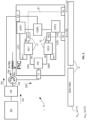
- a system 1 for interrogating at least one sensor of the birefringent Fiber Bragg Grating FBG type (hereafter also sometimes named birefringent Bi-FBG sensor for the sake of brevity), e.g., a Bi-FBG type sensor obtained in a birefringent fiber, or in an optical fiber zone made birefringent.
- Such a system comprises a broadband optical radiation source BS, an integrated photonic detection device PIC, and electronic processing means 2 operatively connected with said integrated photonic device PIC.
- the broadband optical radiation source BS is configured to illuminate the aforesaid at least one sensor of the birefringent Fiber Bragg Grating Bi-FBG type with a broadband optical excitation radiation OA.
- the integrated photonic detection device PIC comprises a first input port C1, operatively connectable to the aforesaid at least one optical fiber sensor of the birefringent Fiber Bragg Grating Bi-FBG type to receive the reflected optical spectrum OR from the sensor, and a second input port C2, operatively connected to said broadband optical radiation source BS to receive the aforesaid broadband optical excitation radiation OA.
- the integrated photonic detection device PIC comprises a polarization optical beam splitter PS, local oscillator signal generation means, first heterodyne optical detection means, second heterodyne optical detection means, a first output port U1, and a second output port U2.
- the polarization optical beam splitter PS is configured to separate a first component of the aforesaid reflected optical spectrum OR1, characterized by a first optical polarization generated by the birefringence and centered around a first frequency ⁇ 1, from a second component of the aforesaid reflected optical spectrum OR2 by a second optical polarization generated by the birefringence and centered around a second frequency ⁇ 2.
- the local oscillator signal generation means are configured to obtain at least two narrowband optical signals (LO1, LO2) comprising a first local oscillator optical signal LO1, centered around a first local oscillator frequency ⁇ LO1 , and a second local oscillator optical signal LO2, centered around a second local oscillator frequency ⁇ LO2 .
- LO1, LO2 narrowband optical signals
- Such local oscillator signal generation means comprise at least one tunable narrowband optical bandpass filter OTF, configured to perform narrowband optical filtering of said broadband optical excitation radiation OA.
- the first optical heterodyne detection means are configured to receive the aforesaid first component of the reflected optical spectrum OR1 and the aforesaid first local oscillator optical signal LO1 and generate, by means of heterodyne detection or reception techniques, on the basis of the first component of the reflected optical spectrum OR1 and of the first local oscillator optical signal LO1, a first electrical signal E1 at a first intermediate frequency ⁇ IFs , equal to the difference between the first local oscillator frequency w LO1 and the aforesaid first frequency ⁇ 1 of the first component of the reflected optical spectrum OR1.
- the second optical heterodyne detection means are configured to receive the aforesaid second component of the reflected optical spectrum OR2 and the aforesaid second local oscillator optical signal LO2 and generate, by means of heterodyne detection techniques, on the basis of the second component of the reflected optical spectrum OR2 and of the second local oscillator optical signal LO2, a second electrical signal E2 at a second intermediate frequency ⁇ IFf , equal to the difference between the second local oscillator frequency ⁇ LO2 and the aforesaid second frequency ⁇ 2 of the second component of the reflected optical spectrum OR2.
- the first output port U1 configured to make the first electrical signal E1 available
- a second output port U2 configured to make the second electrical signal E2 available.
- the electronic processing means are operatively connected with the integrated PIC photonic device to receive the aforesaid first electrical signal E1 and second electrical signal E2 and are configured to determine the aforesaid first intermediate frequency ⁇ IFs , indicative of a first wavelength offset ⁇ 1 of the first component of the reflected optical spectrum OR1, having the first polarization, with respect to a first reference wavelength ⁇ ref1 .
- the electronic processing means are further configured to determine the aforesaid second intermediate frequency ⁇ IF2 , indicative of a second wavelength shift ⁇ 2 of the second component of the reflected optical spectrum OR2, having the second polarization, with respect to a second reference wavelength ⁇ ref2 .
- the aforesaid first wavelength shift ⁇ 1 and second wavelength shift ⁇ 2 are representative of at least one physical magnitude measured by the optical fiber sensor Bi-FBG.
- the aforesaid means of generating local oscillator signals comprise a tunable narrowband OTF optical filter and an optical beam splitter.
- the narrowband optical tunable OTF is configured to narrowband filter the aforesaid broadband optical excitation radiation OA, and to generate a narrowband optical signal centered around a local oscillator frequency ⁇ LO adapted to act as a local oscillator signal LO.
- the optical beam splitter is configured to split the aforesaid narrowband optical signal and to make two attenuated replicas of the narrowband optical signal itself received as input corresponding, respectively, to the first local oscillator signal LO1 and the second local oscillator signal LO2 available to two output ports of the optical beam splitter.
- the system comprises a device for coupling and a device for splitting (or divide) the two orthogonal polarizations, corresponding to the fast axis and the slow axis, into two optical waveguides.
- the device for splitting (or dividing) the two orthogonal polarizations in several possible implementation options, is for example a two-dimensional 2D grating coupler or an edge coupler combined with a polarization rotator and splitter (PSR).
- PSR polarization rotator and splitter
- the system further comprises two different integrated photonic circuits which implement heterodyne detection schemes.
- the two orthogonal polarizations at different frequencies/wavelengths, reflected by the birefringent Bi-FBG, are separated and coupled to two single-mode waveguides, in which the two signals at different frequencies/wavelengths are analyzed separately.
- the two signals are separately combined, by means of two integrated optical couplers, with a local oscillator signal, and then mixed in integrated photodiodes to detect the frequency deviation of the two individual peaks, through heterodyne detection.
- the light coming from a broadband source BS is divided by an optical splitter (“splitter”) OS and sent to both the first port of an optical circulator 3 and an input port of the photonic integrated circuit PIC.
- splitter optical splitter
- the birefringent Bi-FBG sensor is interrogated by the broadband source BS through the second port of the optical circulator, and the reflected optical power from the birefringent Bi-FBG sensor is collected by the third port of the optical circulator and coupled to the chip implementing the PIC integrated photonic circuit.
- the integrated PIC photonic circuit comprises an optical coupler C1 and a signal polarization splitter PS (wherein the polarization splitter, or polarization optical beam splitter may comprise, as noted above, a 2D grating coupler or a PSR), with respect to the fast and slow axis polarizations reflected by the birefringent Bi-FBG sensor.
- the integrated photonic circuit PIC further comprises an additional optical coupler C2 (e.g., a one-dimensional grating coupler or an "edge" coupler) configured to couple broadband light to the integrated photonic circuit.
- an additional optical coupler C2 e.g., a one-dimensional grating coupler or an "edge” coupler
- the photonic integrated circuit PIC further comprises:
- the coupler couples the light reflected from the third port of the optical circulator to the PIC optical chip, and the PS polarization splitter separates the light by sending it into two different optical waveguides; the two orthogonal polarizations reflected from the birefringent Bi-FBG sensor at the frequencies of the fast axis ⁇ s and the slow axis ⁇ f are coupled and sent into two different waveguides of the PIC integrated photonic circuit.
- the scheme further comprises a polarization rotator or a 2D grating coupler to couple the light separated by the splitter into two waveguides TE.
- the broadband light coupled and supplied as input to another input port on the PIC chip is filtered by a tunable optical band-pass filter OTF to select a specific wavelength.
- the tunable filter is based on an extraction (drop) port of a tunable micro-ring resonator.
- the filtered light at a selected wavelength operates as a local LO oscillator, and is split and sent to two different integrated optical couplers OC1, OC2 and combined with light at the frequencies of the slow polarization axis ⁇ s and the fast polarization axis ⁇ f.
- Each coupler combines the frequency of the local LO oscillator and a respective one of the two frequencies ws and ⁇ f, and the output signal of the optical coupler is sent to an integrated photodiode according to a heterodyne configuration.
- the two optical signals and the local oscillator propagate in the waveguide with the same cross-section and polarization, providing the maximum polarization match for heterodyne detection.
- the aforesaid generating means of local oscillator signals comprise an optical beam splitter OSPL, a first tunable narrow-band-pass optical filter OTF1, and a second tunable narrow-band-pass optical filter OTF2.
- the optical beam splitter OSPL is configured to split the aforesaid broadband optical excitation radiation OA, to obtain a first replica of the broadband optical excitation radiation and a second replica of the broadband optical excitation radiation.
- the first narrowband optical tunable OTF1 is configured to narrowband filter the aforesaid first replica of the broadband optical excitation radiation, and to generate the first narrowband optical signal LO1 centered around the first local oscillator frequency ⁇ LO1 .
- the second narrowband optical tunable OTF2 is configured to narrowband filter the aforesaid second replica of the broadband optical excitation radiation, and to generate the second narrowband optical signal LO2 centered around the second local oscillator frequency ⁇ LO2 .
- the PIC device comprises two different tunable narrowband optical filters, OTF1, OTF2, configured to select two independent local oscillators at two different frequencies ⁇ LO1 and ⁇ LO2 .
- this embodiment which uses two independent local oscillators, offers greater flexibility in the heterodyne detection scheme, because it allows for independent control of intermediate frequencies, i.e., the beat frequencies between the local oscillator and the "slow" and “fast” polarized optical signals.
- Such flexibility leads to additional advantages, for example, it makes it possible to reduce the bands required to the photodiodes, thus reducing the noise at their input and thus improving the signal-to-noise ratio SNR of the measurement.
- the first heterodyne detection means include first optical coupler OC1 comprising a respective optical waveguide, configured to combine the first component of the reflected optical spectrum OR1 and the first local oscillator optical signal LO1, and include a first opto-electronic receiver PD1 configured to receive the output optical signal from the first optical coupler OC1 and convert it into a respective first electrical signal E1.
- the second heterodyne detection means include a second optical coupler OC2 comprising a respective optical waveguide, configured to combine the second component of the reflected optical spectrum OR2 and the second local oscillator optical signal LO2; and include a second opto-electronic receiver PD2 configured to receive the output optical signal from the second optical coupler OC2 and convert it into a respective second electrical signal E2.
- the first and second means of heterodyne detection or reception are implemented by means of heterodyne detection or reception devices known in themselves.
- Figure 7 shows a well-known example of a heterodyne mixing technique, which allows to lower the frequency of an optical frequency signal obtaining a corresponding intermediate frequency signal which can be easily detected by electronic reception.
- a mixing between an optical signal and a local oscillator can be achieved by means of a photodiode, i.e., a detector with a quadratic detection law in which two electromagnetic fields, corresponding respectively to the incoming signal E s (t) and the local oscillator E LO (t) are mixed providing a photocurrent i(t) which is proportional to the square of the two input electromagnetic fields.
- a photodiode i.e., a detector with a quadratic detection law in which two electromagnetic fields, corresponding respectively to the incoming signal E s (t) and the local oscillator E LO (t) are mixed providing a photocurrent i(t) which is proportional to the square of the two input electromagnetic fields.
- ⁇ is the power coupling coefficient of the optical coupler (shown in figure 7 )
- ⁇ is the polarization state difference angle between the optical signal and the local oscillator
- ⁇ is the relative phase difference.
- the aforementioned first optical coupler OC1 is a 2x2 optical coupler, configured to output two optical beat signals, resulting from the combination of the first reflected optical spectrum component OR1 and the first local oscillator optical signal LO1.
- said first opto-electronic receiver B-PD1 comprises two photodiodes, configured to perform a balanced detection, wherein the first electrical signal E1 is obtained as a subtraction of the outgoing currents from the two photodiodes of the first opto-electronic receiver B-PD1.
- the aforesaid second optical coupler OC2 is a 2x2 optical coupler, configured to output two optical beat signals, resulting from the combination of the second reflected optical spectrum component OR2 and the second local oscillator optical signal LO2.
- said second opto-electronic receiver B-PD2 comprises two photodiodes, configured to perform a balanced detection, in which the second electrical signal E2 is obtained as a subtraction of the outgoing currents from the two photodiodes of the second opto-electronic receiver B-PD2.
- the balanced heterodyne detection is performed using balanced detection techniques known in themselves, such as the one shown in figure 8 .
- Performing a balanced coherent heterodyne detection improves the signal-to-noise ratio SNR of the detected signal and avoids unwanted effects of local oscillator intensity noise.
- the balanced coherent heterodyne detection shown in figure 2 employs a 2x2 optical coupler and two photodiodes in parallel.
- the difference between the two photocurrents provides only one component, namely the intermediate frequency component, which can be expressed as: i t 1 ⁇ i t 2 ⁇ 2 R P s P LO cos ⁇ cos ⁇ IF t + ⁇ ⁇
- the first heterodyne detection means further comprise a first optical phase shifter OPS1, configured to shift, in a controlled manner, the phase of the first local oscillator optical signal LO1, before the input in the first optical coupler OC1.
- the second heterodyne detection means further comprise a second optical phase shifter OPS2, configured to shift a controlled manner, the phase of the second local oscillator optical signal LO2, before the input in the second optical coupler OC2.
- the PIC device integrates two optical phase shifters which can control and modulate the phase of the local optical oscillator signal.
- the phase shifters add a phase control of the local oscillator; the phase of the local oscillator can be modulated by the phase shifter, which advantageously makes it possible to increase the sensitivity of the measurement by a phase control.
- the optical signals at the two frequencies ⁇ s and ⁇ f are coupled together in a directional coupler.
- the system is configured for interrogating a plurality of sensors of the birefringent Fiber Bragg Grating type (Bi-FBG 1- Bi-FBGn) in cascade, each characterized by a respective nominal operating wavelength ( ⁇ 1- ⁇ n).
- Bi-FBG 1- Bi-FBGn the birefringent Fiber Bragg Grating type
- the PS-polarized optical beam splitter is configured to separate a first component and a second component of the overall ORT reflected optical spectrum from the birefringent Fiber Bragg Grating (Bi-FBG1 - Bi-FBGn) sensor cascade.
- the first component of the overall reflected optical spectrum ORT1 comprises the superposition of the first components (OR11-OR1n) with the first optical polarization centered around a respective first frequency ( ⁇ 11- ⁇ 1n), and the second component of the overall reflected optical spectrum ORT2 comprises the superposition of the second components (OR21-OR2n) with second optical polarization centered around a respective second frequency (w21-w2n).
- the system further comprises first and second frequency discrimination or demultiplexing means, and a plurality of first heterodyne detection means, and a plurality of second heterodyne detection means.
- the first frequency discrimination or demultiplexing means AWG1 are configured to spectrally separate the first components (OR11-OR1n) from one another.
- the second frequency discrimination or demultiplexing means AWG2 are configured to spectrally separate the second components (OR21-OR2n) from one another.
- the first heterodyne detection means are configured to operate on respective first components (OR11-OR1n) to obtain a respective plurality of first electrical signals E1n.
- the second heterodyne detection means configured to operate on respective second components (OR21-OR2n) to obtain a respective plurality of second electrical signals E2n.
- both the first and second means of frequency discrimination or demultiplexing are made by means of respective integrated "array waveguide gratings" (AWG) type devices, placed at the output of the polarization splitter, which enable measurements based on WDM - Wavelength Division Multiplexing.
- AWG array waveguide gratings
- the AWG device is an optical device for distributing an optical signal comprising a plurality of N wavelengths, present at a single waveguide input, and making it available at the input of N different output waveguides.
- the wavelength peaks reflected from the N birefringent Bi-FBG sensors are coupled to the PIC device; the N wavelengths each corresponding to the fast axis and slow axis polarized optical signals are separated and sent to two different waveguides, and each individual wavelength is filtered and selected to a respective different output port of the AWG device.
- Each individual wavelength at a respective output port of the AWG device can be detected by any of the previously illustrated schemes with reference to querying a single birefringent Bi-FBG sensor.
- the first and/or second means of frequency discrimination or demultiplexing are made by other types of respective WDM demultiplexing devices, known in themselves.
- the aforementioned tunable narrowband optical bandpass filter OTF is a micro-ring optical resonator filter, known in itself.
- the ring resonator is a structure in which the fiber or optical waveguide is enclosed in a "loop" configuration; when light, at a particular resonant wavelength, passes through the ring (or loop) in constructive interference conditions, the intensity of the light increases in the structure, and light can be extracted/observed at the monitor port of the extraction port at the given resonant wavelength.
- the micro-ring resonator can be designed and integrated into the integrated photonic circuit PIC and can be used as a bandpass filter, or optical switch, or optical intensity modulator.
- the resonant wavelength of the micro-ring resonator depends on the refractive index and geometry of the device (e.g., the size of the optical waveguide and the ring diameter), and the resonant wavelength can be tuned by a small change in the refractive index of the optical waveguide, e.g., by thermal tuning based on a local micro-heater.
- the aforesaid polarization optical beam splitter PS is a polarization optical beam splitter made by means of integrated photonics technique of two-dimensional grating coupler type.
- the aforesaid polarization optical beam splitter PS is a polarization optical beam splitter made by means of the integrated photonics technique of polarization splitter and rotator - PSR type.
- the two-dimensional grating coupler (2D GC) can be considered as the superposition of two one-dimensional grating couplers (1D GC), in which the two orthogonal polarizations coming from the fiber, at the input, are coupled to two polarized optical waveguides TE in the orthogonal direction.
- the two orthogonal polarizations are coupled to the optical waveguide in which the light propagates with the same polarization.
- the signal comprising two orthogonal polarizations is sent to an integrated polarization optical beam splitter, which divides the light into two separate signals with the two orthogonal polarizations TE and TM [see for example; M. R. Watts, H. A. Haus, E. P. Ippen “Integrated mode-evolution-based polarization splitter” Opt. Lett. 30, 967-969 (2005 )]; the separated, TM-polarized signal is sent to a polarization beam rotator, where the polarization is rotated 90° into a TE-polarized signal [ M. R. Watts, H. A. Haus, "Integrated mode-evolution-based polarization rotators," Opt. Lett. 30, 138-140 (2005 )].
- each of the aforesaid first opto-electronic receiver PD1 and/or said second opto-electronic receiver PD2 comprises at least a respective semiconductor photodiode configured to detect and convert optical signals, at the wavelengths considered, into electrical signals.
- the system further comprises an optical circulator 3 having a first circulator port connected to the broadband optical radiation source BS, a second circulator port connected to a birefringent optical fiber containing the sensor of the birefringent Fiber Bragg Grating Bi-FBG type, and a third circulator port connected to an optical input port of the photonic integrated device PIC.
- Such an optical circulator 3 is configured to transmit the broadband optical radiation OA, received from the first circulator port, to the birefringent optical fiber containing the sensor of the Fiber Bragg Grating Bi-FBG type, through the second circulator port, and it is further configured to convey the spectrum reflected by the sensor of the birefringent Fiber Bragg Grating Bi-FBG type, received from the second circulator port to the optical input port of the photonic integrated device PIC, through the third circulator port.
- the aforesaid first reference wavelength ⁇ ref1 and said second reference wavelength ⁇ ref2 correspond to two respective nominal operating wavelengths of the sensor of the birefringent Fiber Bragg Grating Bi-FBG type, on the two fast and slow channels, determined by means of an initial calibration
- the aforesaid first reference wavelength ⁇ ref1 and said second reference wavelength ⁇ ref2 coincide and correspond to a reference wavelength ⁇ i identified by the tuning of the narrowband band-pass optical tunable filter OTF.
- the aforesaid first reference wavelength ⁇ ref1 and second reference wavelength ⁇ ref2 correspond, respectively, to two reference wavelengths ⁇ i1 and ⁇ i2 identified by the tuning of the two narrowband band-pass optical tunable filters (OTF1, OTF2).
- the aforesaid first reference wavelength ⁇ ref1 and the aforesaid said second reference wavelength ⁇ ref2 coincide and correspond to two respective nominal operating wavelengths of the sensor of the birefringent Fiber Bragg Grating Bi-FBG type, on the two fast and slow channels.
- Such a system comprises a sensor of the birefringent Fiber Bragg Grating Bi-FBG type, a system for interrogating at least one birefringent Fiber Bragg Grating Bi-FBG type according to any one of the embodiments described above, wherein the electronic processing means are further configured to determine the at least two physical magnitudes on the basis of a processing of said first intermediate frequency ⁇ IF1 and second intermediate frequency ⁇ IF2 detected.
- the two determined physical magnitudes are a longitudinal strain and a transverse strain.
- the two determined physical magnitudes are a strain and a temperature.
- the birefringent Fiber Bragg Grating Bi-FBG type sensor is configured to operate in a brake pad or embedded in or attached to a brake caliper, or embedded in a washer device adapted to be placed between a brake caliper bracket and a brake caliper.
- the at least two physical magnitudes detected are a longitudinal strain and a transverse strain, which are present at the point where the birefringent Fiber Bragg Grating (Bi-FBG) sensor is located and which, as a whole, represent a clamping force and/or braking torque acting on the brake caliper.
- Bi-FBG Birefringent Fiber Bragg Grating
- the system according to the invention is a simple and compact system, in which the essential components are integrated (e.g., in photonic integrated circuits in PIC technology).
- the system and method for interrogating Bi-FBG sensors made of birefringent fiber, according to the invention meets the criteria of (i) compactness and simplicity in structure and in use, (ii) effectiveness in performance.
- the solution of the present invention includes optical division based on polarization of the spectrum reflected by the birefringent Bi-FBG sensor, and subsequent double heterodyne coherent detection (functions that can be accomplished by components that can be integrated into a PIC).
- the interrogating system provided by the present invention is sufficiently small and simple, while remaining effective, to be installed in technical contexts, such as strain and temperature sensing in brake calipers, and very suitable for brake pads.
- the advantages, already mentioned above, offered by the birefringent Bi-FBG sensor are particularly apparent, including in particular the ability to simultaneously detect at least two magnitudes or physical parameters (e.g., transverse strain and longitudinal strain, or strain and temperature).
Landscapes
- Physics & Mathematics (AREA)
- General Physics & Mathematics (AREA)
- Optical Transform (AREA)
- Measuring Temperature Or Quantity Of Heat (AREA)
- Length Measuring Devices By Optical Means (AREA)
Claims (16)
- Verfahren zum Abfragen wenigstens eines Sensors des doppelbrechenden Faser-Bragg-Gitter Typs (Bi - FBG), umfassend die Schritte aus:- Illuminieren des wenigstens einen Sensors des doppelbrechenden Faser-Bragg-Gitter Typs (Bi - FBG) mit einer breitbandigen optischen Anregungsstrahlung (OA);- Befördern des reflektierten optischen Spektrums (OR), welches durch den wenigstens einen Sensor des doppelbrechenden Faser-Bragg-Gitter Typs (Bi - FBG) reflektiert wird, in eine Photonische integrierte Schaltung-(PIC)-Detektion;- Aufteilen einer ersten Komponente des reflektierten optischen Spektrums (OR1), gekennzeichnet durch eine erste optische Polarisation, welche durch die Doppelbrechung erzeugt wird und um eine erste Frequenz (ω1) zentriert ist, von einer zweiten Komponente des reflektierenden optischen Spektrums (OR2), gekennzeichnet durch eine zweite optische Polarisation, welche durch die Doppelbrechung erzeugt wird und um eine zweite Frequenz (ω2) zentriert ist, mit Hilfe eines optischen Polarisationsstrahlenteilers (PS), welcher in der photonische integrierte Schaltung-(PIC)-Detektion umfasst ist;- Bereitstellen der breitbandigen optischen Anregungsstrahlung (OA) für die photonische integrierte Schaltung-(PIC)-Detektion;- Erhalten wenigstens zweier schmalbandiger optischer Signale (LO1, LO2), auf Grundlage wenigstens eines schmalbandigen optischen Filterns der breitbandigen optischen Anregungsstrahlung (OA), welche in der Photonische integrierte Schaltung-(PIC)-Detektion durchgeführt wird, wobei die wenigstens zwei schmalbandigen optischen Signale (LO1, LO2) ein optisches Signal (LO1) eines ersten Lokaloszillators, welches um eine erste Lokaloszillatorfrequenz (ωLO1) zentriert ist, und ein optisches Signal (LO2) eines zweiten Lokaloszillators umfassen, welches um eine zweite Lokaloszillatorfrequenz (ωLO2) zentriert ist;- Bereitstellen der ersten Komponente des reflektierten optischen Spektrums (OR1) und des optischen Signals (LO1) eines ersten Lokaloszillators für erste optische Heterodyn-Detektionsmittel, welche in der photonische integrierte Schaltung-(PIC)-Detektion integriert sind, um eine Heterodyn-Detektion durchzuführen und ein erstes elektrisches Signal (E1) an einer ersten Zwischenfrequenz (ωIFs) zu erhalten, gleich der Differenz zwischen der ersten Lokaloszillatorfrequenz (ωLO1) und der ersten Frequenz (ω1) der ersten Komponente des reflektierten optischen Spektrums (OR1);- Bereitstellen der zweiten Komponente des reflektierten optischen Spektrums (OR2) und des optischen Signals (LO2) eines zweiten Lokaloszillators zu zweiten optischen Heterodyn-Detektionsmitteln, welche in der photonische integrierte Schaltung-(PIC)-Detektion integriert sind, um eine Heterodyn-Detektion durchzuführen und ein zweites elektrisches Signal (E2) an einer zweiten Zwischenfrequenz (ωIFf) zu erhalten, gleich der Differenz zwischen der zweiten Lokaloszillatorfrequenz (ωLO2) und der zweiten Frequenz (ω2) der zweiten Komponente des reflektierten optischen Spektrums (OR2);- Bestimmen der ersten Zwischenfrequenz (ωIF1), indikativ einer ersten Wellenlängenverschiebung (Δλ1) der ersten Komponente des reflektierten optischen Spektrums (OR1), welche die erste Polarisation aufweist, mit Bezug zu einer ersten Referenzwellenlänge (λref1 ; λi);- Bestimmen der zweiten Zwischenfrequenz (ωIF2), indikativ einer zweiten Wellenlängenverschiebung (Δλ2) der zweiten Komponente des reflektierten optischen Spektrums (OR2), welche die zweite Polarisation aufweist, mit Bezug zu einer zweiten Referenzwellenlänge (λref2) des Bragg-Gitters des Sensors des doppelbrechenden Faser-Bragg-Gitter Typs (Bi - FBG);wobei die erste Wellenlängenverschiebung (Δλ1) und die zweite Wellenlängenverschiebung (Δλ2) repräsentativ für wenigstens eine physikalische Größe sind, welche durch den Sensor des doppelbrechenden Faser-Bragg-Gitter Typs (Bi - FBG) gemessen wird.
- Verfahren nach Anspruch 1, wobei der Schritt eines Erhaltens von wenigstens zwei schmalbandigen optischen Signalen (LO1, LO2) umfasst:- schmalbandiges Filtern der breitbandigen optischen Anregungsstrahlung (OA), mit Hilfe eines schmalbandigen optischen abstimmbaren Bandpass-Filters (OTF), welcher in der photonische integrierte Schaltung-(PIC)-Detektion integriert ist, um ein schmalbandiges optisches Signal zu erhalten, welches um eine Lokaloszillatorfrequenz (ωLO) zentriert ist, welche dazu eingerichtet ist, als Lokaloszillatorsignal (LO) zu agieren;- Aufspalten des schmalbandigen optischen Signals mit Hilfe eines optischen Strahlenteilers (OSPL), welcher dazu eingerichtet ist, zwei gedämpfte Replika des gleichen schmalbandigen optischen Signals, welches als Eingabe erhalten wird, an zwei Ausgangsanschlüssen verfügbar zu machen,wobei das erste Lokaloszillatorsignal (LO1) und das zweite Lokaloszillatorsignal (LO2) die zwei Signale sind, welche identisch zueinander sind, vorhanden an den zwei Ausgangsanschlüssen des optischen Strahlenteilers,
oderwobei der Schritt des Erhaltens von wenigstens zwei schmalbandigen optischen Signalen (LO1, LO2) umfasst:- Aufspalten der breitbandigen optischen Anregungsstrahlung (OA) mit Hilfe eines optischen Strahlenteilers (OSPL), um ein erstes Replika der breitbandigen optischen Anregungsstrahlung und ein zweites Replika der breitbandigen optischen Anregungsstrahlung zu erhalten;- schmalbandiges Filtern der ersten Replika der breitbandigen optischen Anregungsstrahlung, mit Hilfe eines ersten schmalbandigen optischen abstimmbaren Bandpass-Filter (OTF1), welcher in der photonische integrierte Schaltung-(PIC)-Detektion integriert ist, um das erste schmalbandige optische Signal zu erhalten, welches um eine erste Lokaloszillatorfrequenz (ωLO1) zentriert ist;- schmalbandiges Filtern der zweiten Replika der breitbandigen optischen Anregungsstrahlung, mit Hilfe eines zweiten schmalbandigen optischen abstimmbaren Bandpass-Filters (OTF2), welcher in der photonische integrierte Schaltung-(PIC)-Detektion integriert ist, um das zweite schmalbandige optische Signal zu erhalten, welches um eine zweite Lokaloszillatorfrequenz (ωLO2) zentriert ist. - Verfahren nach einem der Ansprüche 1 bis 2, wobei der Schritt eines Durchführens einer Heterodyn-Detektion und eines Erhaltens eines ersten elektrischen Signals (E1) ein Kombinieren der ersten Komponente des reflektierten optischen Spektrums (OR1) und des optischen Signals (LO1) eines ersten Lokaloszillators in einer optischen Wellenführung eines ersten optischen Kopplers (OC1) der ersten optischen Heterodyn-Detektionsmittel umfasst und ferner ein Umwandeln des optischen Signals, welches an dem Ausgang des ersten optischen Kopplers erhalten wird, in ein jeweiliges erstes elektrisches Signal (E1) umfasst, mit Hilfe eines ersten opto-elektronischen Empfängers (PD1) der ersten optischen Heterodyn-Detektionsmittel;
und wobei der Schritt eines Durchführens einer Heterodyn-Detektion und eines Erhaltens eines zweiten elektrischen Signals (E2) ein Kombinieren der zweiten Komponente des reflektierten optischen Spektrums (OR2) und des optischen Signals (LO2) eines zweiten Lokaloszillators in einer optischen Wellenführung eines zweiten optischen Kopplers (OC2) der zweiten optischen Heterodyn-Detektionsmittel umfasst und ferner ein Umwandeln des optischen Signals, welches an dem Ausgang des zweiten optischen Kopplers erhalten wird, in ein jeweiliges zweites elektrisches Signal (E2) umfasst, mit Hilfe eines zweiten opto-elektronischen Empfängers (PD2) des zweiten optischen Heterodyn-Detektionsmittel. - Verfahren nach Anspruch 3, wobei jeder der Schritte eines Durchführens einer Heterodyn-Detektion, um ein erstes elektrisches Signal (E1) und ein zweites elektrisches Signal (E2) zu erhalten, ein Durchführen einer ausgewogenen Detektion umfasst, unter Verwendung eines jeweiligen 2x2 optischen Kopplers, welcher dazu eingerichtet ist, als Ausgabe zwei optische Signale bereitzustellen, für jede Heterodyn-Detektion, welche durch zwei jeweilige Fotodioden für die ausgewogene Detektion detektiert werden, für jede Heterodyn-Detektion, wobei jedes aus dem ersten elektrischen Signal (E1) und dem zweiten elektrischen Signal (E2) als Subtraktion der Ströme erhalten wird, welche von den jeweiligen Fotodioden ausgegeben werden,oder wobei ein Durchführen der ersten Heterodyn-Detektion ferner ein Verschieben, in einer kontrollierten Weise, der Phase des optischen Signals (LO1) eines ersten Lokaloszillators mit Hilfe eines ersten optischen Phasenschiebers (OPS1) umfasst, welcher in der photonische integrierte Schaltung-(PIC)-Detektion umfasst ist, vor der Eingabe in den ersten optischen Koppler (OC1), und wobei ein Durchführen der zweiten Heterodyn-Detektion ferner ein Verschieben, in einer kontrollierten Weise, der Phase des zweiten Lokaloszillator optischen Signals (LO2) mit Hilfe eines zweiten optischen Phasenschiebers (OPS2) umfasst, welcher in der Photonische integrierte Schaltung-(PIC)-Detektion umfasst ist, vor der Eingabe in den zweiten optischen Koppler (OC2),
oderwobei der Schritt eines Durchführens einer Heterodyn-Detektion ein Injizieren der ersten Komponente des reflektierten optischen Spektrums (OR1) und der zweiten Komponente des reflektierten optischen Spektrums (OR2) in einen einzelnen 2x1 optischen Koppler (OC) umfasst, welcher dazu eingerichtet ist, als Ausgabe ein optisches Signal an einer Zwischenfrequenz (ωIF) zu erzeugen, repräsentativ der Differenz zwischen der Frequenzdeviationen der ersten Komponente des reflektierten optischen Spektrums (OR1) und der zweiten Komponente des reflektierten optischen Spektrums (OR2). - Verfahren nach einem der vorhergehenden Ansprüche, welches dazu eingerichtet ist, eine Mehrzahl von Sensoren des doppelbrechenden Faser-Bragg-Gitter Typs (Bi - FBG1 - Bi - FBGn) in Kaskade abzufragen, gekennzeichnet durch eine jeweilige nominale Betriebswellenlänge (λ1 - λn), wobei- der Schritt eines Beförderns ein Befördern des gesamten reflektierten optischen Spektrums (ORT) umfasst, welches durch die Kaskade von Sensoren des doppelbrechenden Faser-Bragg-Gitter Typs (Bi - FBG1 - Bi - FBGn) reflektiert wird, in einer photonische integrierte Schaltung-(PIC)-Detektion;- der Schritt eines Aufteilens ein Aufteilen einer ersten Komponente des gesamten reflektierten optischen Spektrums (ORT1) und einer zweiten Komponente des gesamten reflektierten optischen Spektrums (ORT2) umfasst,wobei die erste Komponente des gesamten reflektierten optischen Spektrums (ORT1) eine Superposition der ersten Komponenten (OR11 - OR1n) mit einer ersten optischen Polarisation umfasst, welche jeweils um eine jeweilige erste Frequenz (ω11 - ω1n) zentriert sind, und die zweite Komponente des gesamten reflektierten optischen Spektrums (ORT2) eine Superposition der zweiten Komponenten (OR21 - OR2n) mit einer zweiten optischen Polarisation umfasst, welche jeweils um eine jeweilige zweite Frequenz (ω21- ω2n) zentriert sind;wobei das Verfahren die weiteren Schritte umfasst von:- spektrales Aufteilen der ersten Komponenten (OR11 - OR1n) voneinander mit Hilfe erster Frequenzdiskriminierungs- oder Demultiplexiermittel (AWG1);- spektrales Aufteilen der zweiten Komponenten (OR21 - OR2n) voneinander mit Hilfe zweiter Frequenzdiskriminierungs- oder Demultiplexiermittel (AWG2);- Durchführen der Heterodyn-Detektionsschritte an jeder der ersten Komponenten (OR11 - OR1n) und jeder der zweiten Komponenten (OR21 - OR2n), um eine jeweilige Mehrzahl von ersten elektrischen Signalen (E1k) und zweiten elektrischen Signalen (E2k) zu erhalten;- Durchführen der Schritte eines Bestimmens der ersten Zwischenfrequenz (ωIFs,k) und der zweiten Zwischenfrequenz (ωIFf,k) für jedes Paar eines ersten elektrischen Signals (E1k) und eines zweiten elektrischen Signals (E2k), welche einem jeweiligen Sensor des doppelbrechenden Faser-Bragg-Gitter Typs (Bi - FBG) entsprichen.
- Verfahren nach einem der vorhergehenden Ansprüche, wobei die erste optische Polarisation der Polarisation an einer "langsamen Polarisationsachse" entspricht und die erste Doppelbrechungsspitzenfrequenz (ω1) der langsamen Achsen-Doppelbrechungsspitzenfrequenz (ωs) entspricht;und wobei die zweite optische Polarisation orthogonal zu der ersten optischen Polarisation ist und der Polarisation an einer "schnellen Polarisationsachse" entspricht, orthogonal zu der "langsamen Polarisationsachse", und die zweite Doppelbrechungsspitzenfrequenz (ω2) der schnellen Achsen-Doppelbrechungsspitzenfrequenz (ωf) entspricht;oder wobei die erste Referenzwellenlänge (λref1) und die zweite Referenzwellenlänge (λref2) zwei jeweiligen nominal betriebenen Wellenlängen des Sensors des doppelbrechenden Faser-Bragg-Gitter Typs (Bi - FBG) entsprechen, an den zwei schnellen und langsamen Kanälen, welche mit Hilfe einer initialen Kalibrierung bestimmt werden.
- Verfahren nach einem der Ansprüche 2 bis 6, wobei die erste Referenzwellenlänge (λref1) und die zweite Referenzwellenlänge (λref2) übereinstimmen und einer Referenzwellenlänge (λi) entsprechen, welche durch das Einstellen des schmalbandigen optischen abstimmbaren Bandpass-Filters (OTF) identifiziert werden,
oder
wobei die erste Referenzwellenlänge (λref1) und die zweite Referenzwellenlänge (λref2) jeweils zwei Referenzwellenlängen (λi1, λi2) entsprechen, welche durch das jeweilige Einstellen von den zwei schmalbandigen optischen abstimmbaren Bandpass-Filter (OTF1, OTF2) identifiziert werden. - Verfahren zum Bestimmen von wenigstens zwei physikalischen Größen, welche durch einen Sensor des doppelbrechenden Faser-Bragg-Gitter Typs (Bi - FBG) detektierbar sind, umfassend:- Durchführen eines Verfahrens zum Abfragen wenigstens eines Sensors des doppelbrechenden Faser-Bragg-Gitter Typs (Bi - FBG), nach einem der Ansprüche 1 bis 7;- Bestimmen von wenigstens zwei physikalischen Größen auf Grundlage eines Verarbeitens der ersten Zwischenfrequenz (ωIFs) und der zweiten Zwischenfrequenz (ωIFf).
- Verfahren nach Anspruch 8, wobei die zwei bestimmten physikalischen Größen Längsdehnung und eine Querdehnung sind,
oder wobei die zwei bestimmten physikalischen Größen eine Dehnung und eine Temperatur sind. - System (1) zum Abfragen wenigstens eines Sensors des doppelbrechenden Faser-Bragg-Gitter Typs (Bi - FBG), umfassend:- eine breitbandige optische Strahlungsquelle (BS), welche dazu eingerichtet ist, den wenigstens einen Sensor des doppelbrechenden Faser-Bragg-Gitter Typs (Bi - FBG) mit einer breitbandigen optischen Anregungsstrahlung (OA) zu illuminieren;- eine photonische integrierte Schaltung-(PIC)-Detektion, welche einen ersten Eingabeanschluss (C1) aufweist, betriebsfähig verbunden mit dem wenigstens einen Sensor des doppelbrechenden Faser-Bragg-Gitter Typs (Bi - FBG), um das reflektierte optische Spektrum (OR) von dem Sensor zu empfangen, und einen zweiten Eingabeanschluss (C2) aufweist, betriebsfähig verbunden mit der breitbandigen optischen Strahlungsquelle (BS), um die breitbandige optische Anregungsstrahlung (OA) zu empfangen;wobei die photonische integrierte Schaltung-(PIC)-Detektion umfasst:- einen optischen Polarisationsstrahlenteiler (PS), welcher dazu eingerichtet ist, eine erste Komponente des reflektierten optischen Spektrums (OR1), gekennzeichnet durch eine erste optische Polarisation, welche durch die Doppelbrechung erzeugt wird und um eine erste Frequenz (ω1) zentriert ist, von einer zweiten Komponente des reflektierenden optischen Spektrums (OR2) aufzuteilen, gekennzeichnet durch eine zweite optische Polarisation, welche durch die Doppelbrechung erzeugt wird und um eine zweite Frequenz (ω2) zentriert ist;- Mittel für ein Erzeugen von Lokaloszillatorsignalen, welche dazu eingerichtet sind, wenigstens zwei schmalbandige optische Signale (LO1, LO2) zu erhalten, welche ein optisches Signal (LO1) eines ersten Lokaloszillators, welches um eine erste Lokaloszillatorfrequenz (ωLO , ωLO1) zentriert ist, und ein optisches Signal (LO2) eines zweiten Lokaloszillators umfasst, welches um eine zweite Lokaloszillatorfrequenz (ωLO , ωLO2) zentriert ist, wobei die Mittel für ein Erzeugen von Lokaloszillatorsignalen wenigstens einen schmalbandigen optischen abstimmbaren Bandpass-Filter (OTF) umfassen, welcher dazu eingerichtet ist, ein schmalbandiges optisches Filtern der breitbandigen optischen Anregungsstrahlung (OA) durchzuführen;- erste optische Heterodyn-Detektionsmittel (11), welche dazu eingerichtet sind, die erste Komponente des reflektierten optischen Spektrums (OR1) und das optische Signal (LO1) eines ersten Lokaloszillators zu erhalten und, mit Hilfe von Heterodyn-Detektionstechniken, auf der Grundlage der ersten Komponente des reflektierten optischen Spektrums (OR1) und des optischen Signals (LO1) eines ersten Lokaloszillators, ein erstes elektrisches Signal (E1) an einer ersten Zwischenfrequenz (ωIFs) zu erzeugen, gleich der Differenz zwischen der ersten Lokaloszillatorfrequenz (ωLO1) und der ersten Frequenz (ω1) der ersten Komponente des reflektierten optischen Spektrums (OR1);- zweite optische Heterodyn-Detektionsmittel (12), welche dazu eingerichtet sind, die zweite Komponente des reflektierten optischen Spektrums (OR2) und das optische Signal (LO2) eines zweiten Lokaloszillators zu erhalten und, mit Hilfe von Heterodyn-Detektionstechniken, auf der Grundlage der zweiten Komponente des reflektierten optischen Spektrums (OR2) und des optischen Signals (LO2) eines zweiten Lokaloszillators, ein zweites elektrisches Signal (E2) an einer zweiten Zwischenfrequenz (ωIFf) zu erzeugen, gleich der Differenz zwischen der zweiten Lokaloszillatorfrequenz (ωLO2) und der zweiten Frequenz (ω2) der zweiten Komponente des reflektierten optischen Spektrums (OR2);- einen ersten Ausgabeanschluss (U1), welcher dazu eingerichtet ist, das erste elektrische Signal (E1) verfügbar zu machen, und einen zweiten Ausgabeanschluss (U2), welcher dazu eingerichtet ist, das zweite elektrische Signal (E2) verfügbar zu machen;und wobei das System ferner umfasst:- elektronische Verarbeitungsmittel (2), welche mit der photonischen integrierten Vorrichtung (PIC) betriebsfähig verbunden sind, um das erste elektrische Signal (E1) und das zweite elektrische Signal (E2) zu empfangen, und dazu eingerichtet sind, die erste Zwischenfrequenz (ωIFs) zu bestimmen, indikativ einer ersten Wellenlängenverschiebung (Δλ1) der ersten Komponente des reflektierten optischen Spektrums (OR1), welche die erste Polarisation aufweist, mit Bezug zu einer ersten Referenzwellenlänge (λref1, λi) des Bragg-Gitters des Sensors des doppelbrechenden Faser-Bragg-Gitter Typs (Bi - FBG), und ebenso dazu eingerichtet sind, die zweite Zwischenfrequenz (ωIFf) zu bestimmen, indikativ einer zweiten Wellenlängenverschiebung (Δλ2) der zweiten Komponente des reflektierten optischen Spektrums (OR2), welche die zweite Polarisation aufweist, mit Bezug zu einer zweiten Referenzwellenlänge (λref2) des Bragg-Gitters des Sensors des doppelbrechenden Faser-Bragg-Gitter Typs (Bi - FBG),wobei die erste Wellenlängenverschiebung (Δλ1) und die zweite Wellenlängenverschiebung (Δλ2) repräsentativ für wenigstens eine physikalische Größe sind, welche durch den Sensor des doppelbrechenden Faser-Bragg-Gitter Typs (Bi - FBG) gemessen werden.
- System (1) nach Anspruch 10, wobei die Mittel für ein Erzeugen von Lokaloszillatorsignalen umfassen:- einen schmalbandigen optischen abstimmbaren Bandpass-Filter (OTF), welcher dazu eingerichtet ist, die breitbandige optische Anregungsstrahlung (OA) schmalbandig zu filtern und ein schmalbandiges optisches Signal zu erzeugen, welches um eine Lokaloszillatorfrequenz (ωLO) zentriert ist, welchs dazu angepasst ist, als Lokaloszillatorsignal (LO) zu agieren;- einen optischen Strahlenteiler (OSPL), welcher dazu eingerichtet ist, das schmalbandige optische Signal (LO) aufzuteilen und zwei gedämpfte Replika des gleichen schmalbandigen optischen Signals an zwei Ausgabeanschlüssen des optischen Strahlenteilers verfügbar zu machen, wobei die gedämpften Replika gedämpfte Replika des gleichen schmalbandigen optischen Signals sind, welche als Eingabe empfangen sind, welche jeweils dem ersten Lokaloszillatorsignal (LO1) und dem zweiten Lokaloszillatorsignal (LO2) entsprechen,wobei die Mittel für ein Erzeugen von Lokaloszillatorsignalen umfassen:
oder- einen optischen Strahlenteiler (OSPL), welcher dazu eingerichtet ist, die breitbandige optische Anregungsstrahlung (OA) aufzuteilen, um ein erstes Replika der breitbandigen optischen Anregungsstrahlung und ein zweites Replika der breitbandigen optischen Anregungsstrahlung zu erhalten;- einen ersten schmalbandigen optischen abstimmbaren Bandpass-Filter (OTF1), welcher dazu eingerichtet ist, das erste Replika der breitbandigen optischen Anregungsstrahlung schmalbandig zu filtern und das erste schmalbandige optische Signal (LO1) zu erzeugen, welches um die erste Lokaloszillatorfrequenz (ωLO1) zentriert ist;- einen zweiten schmalbandigen optischen abstimmbaren Bandpass-Filter (OTF2), welcher dazu eingerichtet ist, das zweite Replika der breitbandigen optischen Anregungsstrahlung schmalbandig zu filtern und das zweite schmalbandige optische Signal (LO2) zu erzeugen, welches um die zweite Lokaloszillatorfrequenz (ωLO2) zentriert ist. - System (1) nach einem der Ansprüche 10 bis 11, wobei:- die ersten Heterodyn-Detektionsmittel umfassen:- einen ersten optischen Koppler (OC1), welcher eine jeweilige optische Wellenführung umfasst, welche dazu eingerichtet ist, die erste Komponente des reflektierten optischen Spektrums (OR1) und das optische Signal (LO1) eines ersten Lokaloszillators zu kombinieren;- einen ersten opto-elektronischen Empfänger (PD1), welcher dazu eingerichtet ist, das optische Ausgabesignal von dem ersten optischen Koppler (OC1) zu empfangen und es in ein jeweiliges erstes elektrisches Signal (E1) umzuwandeln;- die zweiten Heterodyn-Detektionsmittel umfassen:und wobei:- einen zweiten optischen Koppler (OC2), welcher eine jeweilige optische Wellenführung umfasst, welche dazu eingerichtet ist, die zweite Komponente des reflektierten optischen Spektrums (OR2) und das optische Signal (LO2) eines zweiten Lokaloszillators zu kombinieren;- einen zweiten opto-elektronischen Empfänger (PD2), welcher dazu eingerichtet ist, das optische Ausgabesignal von dem zweiten optischen Koppler (OC2) zu empfangen und es in ein jeweiliges zweites elektrisches Signal (E2) umzuwandeln;
oder wobei- die ersten Heterodyn-Detektionsmittel ferner einen ersten optischen Phasenschieber (OPS1) umfassen, welcher dazu eingerichtet ist, in einer kontrollierten Weise, die Phase des optischen Signals (LO1) eines ersten Lokaloszillators zu verschieben, vor der Eingabe in den ersten optischen Koppler (OC1),- die zweiten Heterodyn-Detektionsmittel ferner einen zweiten optischen Phasenschieber (OPS2) umfassen, welcher dazu eingerichtet ist, in einer kontrollierten Weise, die Phase des optischen Signals (LO2) eines zweiten Lokaloszillators zu verschieben, vor der Eingabe in den zweiten optischen Koppler (OC2),- der erste optische Koppler (OC1) ein 2x2 optischer Koppler ist, welcher dazu eingerichtet ist, als Ausgabe zwei optische Schwebungssignale bereitzustellen, abgeleitet von der Kombination der ersten Komponente des reflektierten optischen Spektrums (OR1) und des optischen Signals (LO1) eines ersten Lokaloszillators, und wobei der erste opto-elektronische Empfänger (B-PD1) zwei Fotodioden umfasst, welche dazu eingerichtet sind eine ausgewogene Detektion durchzuführen, wobei das erste elektrische Signal (E1) als Subtraktion der Ströme erhalten wird, welche von den zwei Fotodioden des ersten opto-elektronischen Empfängers (PD1) ausgegeben werden;- der zweite optische Koppler (OC2) ein 2x2 optischer Koppler ist, welcher dazu eingerichtet ist, als Ausgabe zwei optische Schwebungssignale bereitzustellen, abgeleitet von der Kombination der zweiten Komponente des reflektierten optischen Spektrums (OR2) und des optischen Signals (LO2) des zweiten Lokaloszillators, und wobei der zweite opto-elektronische Empfänger (B-PD2) zwei Fotodioden umfasst, welche dazu eingerichtet sind eine ausgewogene Detektion durchzuführen, wobei das zweite elektrische Signal (E2) als Subtraktion der Ströme erhalten wird, welche von den zwei Fotodioden des zweiten opto-elektronischen Empfängers (PD2) ausgegeben werden. - System (1) nach einem der Ansprüche 10 bis 12, welches dazu eingerichtet ist, eine Mehrzahl von Sensoren des doppelbrechenden Faser-Bragg-Gitter Typs (Bi - FBG1 - Bi - FBGn) in Kaskade abzufragen, gekennzeichnet durch eine jeweilige nominale Betriebswellenlänge (λ1 - λn), wobei:- der optische Polarisationsstrahlenteiler (PS) dazu eingerichtet ist, eine erste Komponente (ORT1) und eine zweite Komponente (ORT2) des gesamten reflektierten optischen Spektrums (ORT) von der Kaskade an Sensoren des doppelbrechenden Faser-Bragg-Gitter Typs (Bi-FBG1 - Bi-FBGn) aufzuteilen, wobei die erste Komponente des gesamten reflektierten optischen Spektrums (ORT1) eine Superposition der ersten Komponenten (OR11 - OR1n) mit einer ersten optischen Polarisation umfasst, welche um eine jeweilige erste Frequenz (ω11- ω1n) zentriert ist, und die zweite Komponente des gesamten reflektierten optischen Spektrums (ORT2) eine Superposition der zweiten Komponenten (OR21 - OR2n) mit einer zweiten optischen Polarisation umfasst, welche um eine jeweilige zweite Frequenz (ω21- ω2n) zentriert ist;und wobei das System ferner umfasst:- erste Frequenzdiskriminierungs- oder Demultiplexiermittel (AWG1), welche dazu eingerichtet sind, die ersten Komponenten (OR11 - OR1n) voneinander spektral aufzuteilen;- zweite Frequenzdiskriminierungs- oder Demultiplexiermittel (AWG1), welche dazu eingerichtet sind, die zweiten Komponenten (OR21 - OR2n) voneinander spektral aufzuteilen;- eine Mehrzahl von ersten Heterodyn-Detektionsmitteln, welche dazu eingerichtet sind, auf jeweiligen ersten Komponenten (OR11 - OR1n) betrieben zu sein, um eine jeweilige Mehrzahl von ersten elektrischen Signalen (E1n) zu erhalten;- eine Mehrzahl von zweiten Heterodyn-Detektionsmitteln, welche dazu eingerichtet sind, auf jeweiligen zweiten Komponenten (OR21 - OR2n) betrieben zu sein, um eine jeweilige Mehrzahl von zweiten elektrischen Signalen (E2n) zu erhalten.
- System (1) nach einem der Ansprüche 10 bis 13, wobei der schmalbandige optische abstimmbare Bandpass-Filter (OTF) ein optischer Mikroring-Resonator-Filter ist,und/oder wobei der optische Polarisationsstrahlenteiler (PS) ein optischer Polarisationsstrahlenteiler ist, welcher mit Hilfe einer integrierten photonischen Technik des "zweidimensional Gitter-Koppler" Typs oder mit Hilfe einer integrierten photonischen Technik der "Polarisation Teiler und Rotator - PSR" Typs erzeugt ist,
und/oder
wobei jeder des ersten opto-elektronischen Empfängers (PD1) und/oder des zweiten opto-elektronischen Empfängers (PD2) wenigstens eine jeweilige Halbleiter-Fotodiode umfasst, welche dazu eingerichtet ist, optische Signale zu detektieren und, unter den berücksichtigten Wellenlängen, in elektrische Signale umzuwandeln,und/oder wobei das System (1) ferner einen optischen Zirkulator (3) umfasst, welcher einen ersten Zirkulatoranschluss, welcher mit der breitbandigen optischen Strahlungsquelle (BS) verbunden ist, einen zweiten Zirkulatoranschluss, welcher mit einer doppelbrechenden optischen Faser verbunden ist, welche den Sensor des Faser-Bragg-Gitter Typs (Bi - FBG) enthält, und einen dritten Zirkulatoranschluss aufweist, welcher mit einem optischen Eingabeanschluss der photonischen integrierten Vorrichtung (PIC) verbunden ist,wobei der optische Zirkulator (3) dazu eingerichtet ist, die breitbandige optische Strahlung (OA), welche von dem ersten Zirkulatoranschluss empfangen ist, zu der doppelbrechenden optischen Faser, welche den Sensor des Faser-Bragg-Gitter Typs (Bi - FBG) enthält, durch den zweiten Zirkulatoranschluss zu übertragen, und er ferner dazu eingerichtet ist, das Spektrum, welches durch den Sensor des Faser-Bragg-Gitter Typs (Bi - FBG) reflektiert ist, welches von dem zweiten Zirkulatoranschluss empfangen ist, zu dem optischen Eingabeanschluss der photonischen integrierten Vorrichtung (PIC) zu befördern, durch den dritten Zirkulatoranschluss. - System zum Bestimmen von wenigstens zwei physikalischen Größen, detektierbar durch den Sensor des doppelbrechenden Faser-Bragg-Gitter Typs (Bi - FBG), umfassend:- einen Sensor des doppelbrechenden Faser-Bragg-Gitter Typs (Bi - FBG);- ein System (1) zum Abfragen wenigstens eines Sensors des doppelbrechenden Faser-Bragg-Gitter Typs (Bi - FBG) nach einem der Ansprüche 10 bis 14, wobei die elektronischen Verarbeitungsmittel (2) ferner dazu eingerichtet sind, die wenigstens zwei physikalischen Größen auf Grundlage einer Verarbeitung der detektierten ersten Zwischenfrequenz (ωIFs) und zweiten Zwischenfrequenz (ωIFf) zu bestimmen.
- System nach Anspruch 15, wobei der Sensor des doppelbrechenden Faser-Bragg-Gitter Typs (Bi - FBG) dazu eingerichtet ist, innerhalb eines Bremsbelags oder inkorporiert in oder verbunden mit einem Bremssattel, oder inkorporiert in einer Unterlagenvorrichtung betrieben zu sein, welche dazu eingerichtet ist, zwischen einer Bremssattelstütze und einem Bremssattel angeordnet zu sein, und wobei die wenigstens zwei detektierten physikalischen Größen eine Longitudinaldehnung und eine Transversaldehnung sind, welche an einem Punkt vorhanden sind, wo der Sensor des doppelbrechenden Faser-Bragg-Gitter Typs (Bi - FBG) platziert ist und generell für eine Spannkraft und/oder ein Bremsdrehmoment repräsentativ sind, welches auf den Bremssattel wirkt.
Applications Claiming Priority (2)
| Application Number | Priority Date | Filing Date | Title |
|---|---|---|---|
| IT102020000032027A IT202000032027A1 (it) | 2020-12-23 | 2020-12-23 | Metodo e sistema per interrogare un sensore fibre bragg grating birifrangente, impiegante rilevazione ottica eterodina |
| PCT/IB2021/061767 WO2022137027A1 (en) | 2020-12-23 | 2021-12-15 | Method and system for interrogating a birefringent fiber bragg grating sensor, employing heterodyne optical detection |
Publications (2)
| Publication Number | Publication Date |
|---|---|
| EP4267917A1 EP4267917A1 (de) | 2023-11-01 |
| EP4267917B1 true EP4267917B1 (de) | 2024-10-16 |
Family
ID=74875121
Family Applications (1)
| Application Number | Title | Priority Date | Filing Date |
|---|---|---|---|
| EP21840999.3A Active EP4267917B1 (de) | 2020-12-23 | 2021-12-15 | Verfahren und system zur abfrage eines doppelbrechenden faser-bragg-gitter-sensors unter verwendung von heterodyner optischer detektion |
Country Status (8)
| Country | Link |
|---|---|
| US (1) | US12498280B2 (de) |
| EP (1) | EP4267917B1 (de) |
| JP (1) | JP7763252B2 (de) |
| KR (1) | KR20230124055A (de) |
| CN (1) | CN117242319A (de) |
| ES (1) | ES3010504T3 (de) |
| IT (1) | IT202000032027A1 (de) |
| WO (1) | WO2022137027A1 (de) |
Families Citing this family (8)
| Publication number | Priority date | Publication date | Assignee | Title |
|---|---|---|---|---|
| US11641248B2 (en) * | 2021-03-01 | 2023-05-02 | Google Llc | System, apparatus, and architecture for migrating an optical communication network |
| US11689292B2 (en) | 2021-03-01 | 2023-06-27 | Google Llc | Polarization-folding coherent optical technology for short reach optical communication |
| AU2023371455A1 (en) * | 2022-10-31 | 2025-05-08 | Fmp Group (Australia) Pty Limited | Brake system with sensor |
| DE102023123567A1 (de) * | 2023-09-01 | 2025-03-06 | Zf Cv Systems Global Gmbh | Messvorrichtung zum Überwachen einer Scheibenbremse für ein Fahrzeug, insbesondere Nutzfahrzeug, Scheibenbremse, Messanordnung, Fahrzeug, insbesondere Nutzfahrzeug |
| EP4530582A1 (de) * | 2023-09-26 | 2025-04-02 | Stichting VU | System und verfahren zur abfrage einer photonischen schaltung |
| CN119022972B (zh) * | 2024-08-09 | 2026-01-06 | 武汉理工大学 | 一种异构光栅阵列以及分布式多参量传感系统 |
| NL2039377B1 (en) * | 2024-12-17 | 2026-07-13 | Photonfirst Ip B V | A system and a method of optically measuring at least two different environmental parameters. |
| CN120180099B (zh) * | 2025-05-20 | 2025-08-15 | 江苏深远海洋信息技术与装备创新中心有限公司 | 基于双折射fbg的光纤环境事件识别方法 |
Family Cites Families (24)
| Publication number | Priority date | Publication date | Assignee | Title |
|---|---|---|---|---|
| US5319435A (en) * | 1991-09-04 | 1994-06-07 | Melle Serge M | Method and apparatus for measuring the wavelength of spectrally narrow optical signals |
| US5469265A (en) * | 1992-12-02 | 1995-11-21 | Measures; Raymond M. | Method and apparatus for an optoelectronic smart structure interface with wavelength demodulation of laser sensors |
| US5828059A (en) * | 1996-09-09 | 1998-10-27 | Udd; Eric | Transverse strain measurements using fiber optic grating based sensors |
| GB9700269D0 (en) * | 1997-01-08 | 1997-02-26 | York Sensors Ltd | Improvements to optical time domain reflectometry |
| NO321724B1 (no) * | 1999-06-15 | 2006-06-26 | Optoplan As | Framgangsmate og anordning for malinger av de ortogonalt polariserte Bragg-bolgelengdene fra fiber-Bragg-gitter |
| EP1359394A1 (de) * | 2002-04-30 | 2003-11-05 | Abb Research Ltd. | Hochauflösender Faserlaser-Sensor |
| US20050018944A1 (en) * | 2003-07-25 | 2005-01-27 | Mozdy Eric J. | Polarization modulation interrogation of grating-coupled waveguide sensors |
| US8379217B2 (en) * | 2006-03-23 | 2013-02-19 | General Electric Company | System and method for optical sensor interrogation |
| CA2548022C (en) * | 2006-05-23 | 2014-03-25 | Itf Laboratories Inc. | Method for monitoring and measuring optical properties of device in polarization maintaining fibers by using reference fiber bragg grating and fiber components manufactured thereby |
| US7512291B2 (en) * | 2006-05-31 | 2009-03-31 | Mendoza Edgar A | Fiber bragg crating sensor interrogation method |
| WO2009107838A1 (ja) | 2008-02-29 | 2009-09-03 | 株式会社フジクラ | 光周波数領域反射測定方式の物理量計測装置及びこれを用いた温度と歪みの計測方法 |
| CN101319919B (zh) * | 2008-07-15 | 2011-02-09 | 浙江大学 | 一种频域光纤光栅传感网络解调的方法和设备 |
| CN101532850B (zh) * | 2009-04-20 | 2011-03-30 | 浙江大学 | 一种布拉格光纤光栅传感解调的方法和装置 |
| JP5945120B2 (ja) | 2012-01-12 | 2016-07-05 | 株式会社フジクラ | 光ファイバセンサおよびこれを用いたひずみと温度の同時計測方法 |
| US9735886B2 (en) * | 2014-09-02 | 2017-08-15 | Technion Research And Development Foundation Ltd. | Self-coherent robust spectrally efficient optical transmission systems |
| EP3070437A1 (de) | 2015-03-20 | 2016-09-21 | FAZ Technology Limited | Messsystem und verfahren zum auslesen von doppelbrechenden optischen sensoren auf basis eines frequenz-abtastenden abfragegeräts |
| NL2015448B1 (en) * | 2015-09-16 | 2017-04-03 | Technobis Group B V | Fiber Bragg grating interrogator assembly and method for the same. |
| JP2017181115A (ja) | 2016-03-28 | 2017-10-05 | アンリツ株式会社 | 光周波数領域反射測定装置及び光周波数領域反射測定方法 |
| CN106153225B (zh) * | 2016-06-28 | 2018-11-16 | 南京师范大学 | 一种光纤布拉格光栅横向压力传感器系统及测量方法 |
| GB2566314B (en) * | 2017-09-08 | 2020-07-29 | Exalos Ag | Depolarisers |
| GB2579991B (en) * | 2017-09-19 | 2023-03-08 | Analog Devices Inc | Fiber bragg grating interrogation and sensing system and methods |
| CN108287262B (zh) * | 2018-01-10 | 2020-05-05 | 武汉理工大学 | 全光纤电流互感器温度和振动反馈补偿系统及测量方法 |
| DE102018124435A1 (de) * | 2018-10-03 | 2020-04-09 | Nkt Photonics Gmbh | Verteilte Messvorrichtung |
| GB2622881B (en) * | 2022-09-30 | 2025-04-09 | Exalos Ag | Wavelength-stabilized broadband light source |
-
2020
- 2020-12-23 IT IT102020000032027A patent/IT202000032027A1/it unknown
-
2021
- 2021-12-15 ES ES21840999T patent/ES3010504T3/es active Active
- 2021-12-15 US US18/258,907 patent/US12498280B2/en active Active
- 2021-12-15 JP JP2023538780A patent/JP7763252B2/ja active Active
- 2021-12-15 EP EP21840999.3A patent/EP4267917B1/de active Active
- 2021-12-15 CN CN202180092071.7A patent/CN117242319A/zh active Pending
- 2021-12-15 WO PCT/IB2021/061767 patent/WO2022137027A1/en not_active Ceased
- 2021-12-15 KR KR1020237025198A patent/KR20230124055A/ko active Pending
Also Published As
| Publication number | Publication date |
|---|---|
| US12498280B2 (en) | 2025-12-16 |
| CN117242319A (zh) | 2023-12-15 |
| JP2024502771A (ja) | 2024-01-23 |
| EP4267917A1 (de) | 2023-11-01 |
| ES3010504T3 (en) | 2025-04-03 |
| KR20230124055A (ko) | 2023-08-24 |
| JP7763252B2 (ja) | 2025-10-31 |
| WO2022137027A1 (en) | 2022-06-30 |
| US20240044731A1 (en) | 2024-02-08 |
| IT202000032027A1 (it) | 2022-06-23 |
Similar Documents
| Publication | Publication Date | Title |
|---|---|---|
| US12498280B2 (en) | Method and system for interrogating a birefringent Fiber Bragg Grating sensor, employing heterodyne optical detection | |
| US5361130A (en) | Fiber grating-based sensing system with interferometric wavelength-shift detection | |
| US7324714B1 (en) | Multicore fiber curvature sensor | |
| EP0251632B1 (de) | Messanordnung und Methode mit mehreren Sensoren und einer Pulssignalquelle | |
| US5754293A (en) | Apparatus for the simultaneous acquisition of high bandwidth information in very long arrays containing large numbers of sensor elements | |
| US7081959B2 (en) | Method and apparatus for providing polarization insensitive signal processing for interferometric sensors | |
| US11619783B2 (en) | Sine-cosine optical frequency detection devices for photonics integrated circuits and applications in LiDAR and other distributed optical sensing | |
| CN113218518A (zh) | 一种基于集成光路的正弦-余弦光频率检测装置及其在光学感测中的应用 | |
| CN100552520C (zh) | 一种复用与解调长周期光纤光栅阵列的方法及设备 | |
| US4334781A (en) | Optical sensing system | |
| US12372628B2 (en) | Sine-cosine optical frequency detection devices for photonics integrated circuits and applications in lidar and other distributed optical sensing | |
| US20070127932A1 (en) | Method, system and apparatus for optical phase modulation based on frequency shift | |
| GB2374928A (en) | Fibre optic sensor systems | |
| US4882716A (en) | Optic fiber hydrophone and antenna associating a series of hydrophones | |
| EP4103913B1 (de) | Faseroptischer sensor mit hoher abtastrate | |
| US8953169B2 (en) | Apolarized interferometric system, and apolarized interferometric measurement method | |
| EP1192500B1 (de) | Verfahren und gerät zur fernabfrage der doppelbrechung von auf bragggitterfasern basierenden sensoren | |
| Montero et al. | Self-referenced optical networks for remote interrogation of quasi-distributed fiber-optic intensity sensors | |
| US5381257A (en) | Simultaneous data communication and fiber perturbation detection system | |
| CN115003988B (zh) | 使用多模光纤在测量点测量多个物理参数的系统 | |
| US6298185B1 (en) | Distributed fiber grating sensing systems using birefringence fiber interferometers for detecting wavelength shifts | |
| KR100885408B1 (ko) | 광신호 대 잡음비 검출장치 | |
| JPH0376693B2 (de) | ||
| EP4650723A1 (de) | Optisches sensorsystem zum nachweis einer chemischen substanz | |
| CA2317255A1 (en) | Multichannel optical spectrum slicer and method of measuring modal birefringence and/or polarization mode dispersion of slicer itself |
Legal Events
| Date | Code | Title | Description |
|---|---|---|---|
| STAA | Information on the status of an ep patent application or granted ep patent |
Free format text: STATUS: UNKNOWN |
|
| STAA | Information on the status of an ep patent application or granted ep patent |
Free format text: STATUS: THE INTERNATIONAL PUBLICATION HAS BEEN MADE |
|
| PUAI | Public reference made under article 153(3) epc to a published international application that has entered the european phase |
Free format text: ORIGINAL CODE: 0009012 |
|
| STAA | Information on the status of an ep patent application or granted ep patent |
Free format text: STATUS: REQUEST FOR EXAMINATION WAS MADE |
|
| 17P | Request for examination filed |
Effective date: 20230623 |
|
| AK | Designated contracting states |
Kind code of ref document: A1 Designated state(s): AL AT BE BG CH CY CZ DE DK EE ES FI FR GB GR HR HU IE IS IT LI LT LU LV MC MK MT NL NO PL PT RO RS SE SI SK SM TR |
|
| RIN1 | Information on inventor provided before grant (corrected) |
Inventor name: CAMOZZI, FRANCESCO Inventor name: TOZZETTI, LORENZO Inventor name: DI PASQUALE, FABRIZIO Inventor name: MUANENDA, YONAS SEIFU Inventor name: FARALLI, STEFANO |
|
| DAV | Request for validation of the european patent (deleted) | ||
| DAX | Request for extension of the european patent (deleted) | ||
| GRAP | Despatch of communication of intention to grant a patent |
Free format text: ORIGINAL CODE: EPIDOSNIGR1 |
|
| STAA | Information on the status of an ep patent application or granted ep patent |
Free format text: STATUS: GRANT OF PATENT IS INTENDED |
|
| INTG | Intention to grant announced |
Effective date: 20240508 |
|
| GRAS | Grant fee paid |
Free format text: ORIGINAL CODE: EPIDOSNIGR3 |
|
| GRAA | (expected) grant |
Free format text: ORIGINAL CODE: 0009210 |
|
| STAA | Information on the status of an ep patent application or granted ep patent |
Free format text: STATUS: THE PATENT HAS BEEN GRANTED |
|
| AK | Designated contracting states |
Kind code of ref document: B1 Designated state(s): AL AT BE BG CH CY CZ DE DK EE ES FI FR GB GR HR HU IE IS IT LI LT LU LV MC MK MT NL NO PL PT RO RS SE SI SK SM TR |
|
| REG | Reference to a national code |
Ref country code: GB Ref legal event code: FG4D |
|
| REG | Reference to a national code |
Ref country code: CH Ref legal event code: EP |
|
| REG | Reference to a national code |
Ref country code: IE Ref legal event code: FG4D |
|
| REG | Reference to a national code |
Ref country code: DE Ref legal event code: R096 Ref document number: 602021020478 Country of ref document: DE |
|
| REG | Reference to a national code |
Ref country code: LT Ref legal event code: MG9D |
|
| REG | Reference to a national code |
Ref country code: NL Ref legal event code: MP Effective date: 20241016 |
|
| REG | Reference to a national code |
Ref country code: AT Ref legal event code: MK05 Ref document number: 1733250 Country of ref document: AT Kind code of ref document: T Effective date: 20241016 |
|
| PG25 | Lapsed in a contracting state [announced via postgrant information from national office to epo] |
Ref country code: NL Free format text: LAPSE BECAUSE OF FAILURE TO SUBMIT A TRANSLATION OF THE DESCRIPTION OR TO PAY THE FEE WITHIN THE PRESCRIBED TIME-LIMIT Effective date: 20241016 |
|
| PG25 | Lapsed in a contracting state [announced via postgrant information from national office to epo] |
Ref country code: NL Free format text: LAPSE BECAUSE OF FAILURE TO SUBMIT A TRANSLATION OF THE DESCRIPTION OR TO PAY THE FEE WITHIN THE PRESCRIBED TIME-LIMIT Effective date: 20241016 |
|
| PG25 | Lapsed in a contracting state [announced via postgrant information from national office to epo] |
Ref country code: IS Free format text: LAPSE BECAUSE OF FAILURE TO SUBMIT A TRANSLATION OF THE DESCRIPTION OR TO PAY THE FEE WITHIN THE PRESCRIBED TIME-LIMIT Effective date: 20250216 Ref country code: HR Free format text: LAPSE BECAUSE OF FAILURE TO SUBMIT A TRANSLATION OF THE DESCRIPTION OR TO PAY THE FEE WITHIN THE PRESCRIBED TIME-LIMIT Effective date: 20241016 Ref country code: PT Free format text: LAPSE BECAUSE OF FAILURE TO SUBMIT A TRANSLATION OF THE DESCRIPTION OR TO PAY THE FEE WITHIN THE PRESCRIBED TIME-LIMIT Effective date: 20250217 |
|
| PG25 | Lapsed in a contracting state [announced via postgrant information from national office to epo] |
Ref country code: FI Free format text: LAPSE BECAUSE OF FAILURE TO SUBMIT A TRANSLATION OF THE DESCRIPTION OR TO PAY THE FEE WITHIN THE PRESCRIBED TIME-LIMIT Effective date: 20241016 |
|
| PG25 | Lapsed in a contracting state [announced via postgrant information from national office to epo] |
Ref country code: BG Free format text: LAPSE BECAUSE OF FAILURE TO SUBMIT A TRANSLATION OF THE DESCRIPTION OR TO PAY THE FEE WITHIN THE PRESCRIBED TIME-LIMIT Effective date: 20241016 |
|
| PG25 | Lapsed in a contracting state [announced via postgrant information from national office to epo] |
Ref country code: NO Free format text: LAPSE BECAUSE OF FAILURE TO SUBMIT A TRANSLATION OF THE DESCRIPTION OR TO PAY THE FEE WITHIN THE PRESCRIBED TIME-LIMIT Effective date: 20250116 |
|
| PG25 | Lapsed in a contracting state [announced via postgrant information from national office to epo] |
Ref country code: AT Free format text: LAPSE BECAUSE OF FAILURE TO SUBMIT A TRANSLATION OF THE DESCRIPTION OR TO PAY THE FEE WITHIN THE PRESCRIBED TIME-LIMIT Effective date: 20241016 Ref country code: GR Free format text: LAPSE BECAUSE OF FAILURE TO SUBMIT A TRANSLATION OF THE DESCRIPTION OR TO PAY THE FEE WITHIN THE PRESCRIBED TIME-LIMIT Effective date: 20250117 Ref country code: LV Free format text: LAPSE BECAUSE OF FAILURE TO SUBMIT A TRANSLATION OF THE DESCRIPTION OR TO PAY THE FEE WITHIN THE PRESCRIBED TIME-LIMIT Effective date: 20241016 |
|
| PG25 | Lapsed in a contracting state [announced via postgrant information from national office to epo] |
Ref country code: PL Free format text: LAPSE BECAUSE OF FAILURE TO SUBMIT A TRANSLATION OF THE DESCRIPTION OR TO PAY THE FEE WITHIN THE PRESCRIBED TIME-LIMIT Effective date: 20241016 |
|
| PG25 | Lapsed in a contracting state [announced via postgrant information from national office to epo] |
Ref country code: RS Free format text: LAPSE BECAUSE OF FAILURE TO SUBMIT A TRANSLATION OF THE DESCRIPTION OR TO PAY THE FEE WITHIN THE PRESCRIBED TIME-LIMIT Effective date: 20250116 |
|
| PG25 | Lapsed in a contracting state [announced via postgrant information from national office to epo] |
Ref country code: SM Free format text: LAPSE BECAUSE OF FAILURE TO SUBMIT A TRANSLATION OF THE DESCRIPTION OR TO PAY THE FEE WITHIN THE PRESCRIBED TIME-LIMIT Effective date: 20241016 |
|
| PG25 | Lapsed in a contracting state [announced via postgrant information from national office to epo] |
Ref country code: MC Free format text: LAPSE BECAUSE OF FAILURE TO SUBMIT A TRANSLATION OF THE DESCRIPTION OR TO PAY THE FEE WITHIN THE PRESCRIBED TIME-LIMIT Effective date: 20241016 |
|
| PG25 | Lapsed in a contracting state [announced via postgrant information from national office to epo] |
Ref country code: DK Free format text: LAPSE BECAUSE OF FAILURE TO SUBMIT A TRANSLATION OF THE DESCRIPTION OR TO PAY THE FEE WITHIN THE PRESCRIBED TIME-LIMIT Effective date: 20241016 |
|
| REG | Reference to a national code |
Ref country code: DE Ref legal event code: R097 Ref document number: 602021020478 Country of ref document: DE |
|
| PG25 | Lapsed in a contracting state [announced via postgrant information from national office to epo] |
Ref country code: EE Free format text: LAPSE BECAUSE OF FAILURE TO SUBMIT A TRANSLATION OF THE DESCRIPTION OR TO PAY THE FEE WITHIN THE PRESCRIBED TIME-LIMIT Effective date: 20241016 |
|
| PG25 | Lapsed in a contracting state [announced via postgrant information from national office to epo] |
Ref country code: RO Free format text: LAPSE BECAUSE OF FAILURE TO SUBMIT A TRANSLATION OF THE DESCRIPTION OR TO PAY THE FEE WITHIN THE PRESCRIBED TIME-LIMIT Effective date: 20241016 |
|
| PG25 | Lapsed in a contracting state [announced via postgrant information from national office to epo] |
Ref country code: SK Free format text: LAPSE BECAUSE OF FAILURE TO SUBMIT A TRANSLATION OF THE DESCRIPTION OR TO PAY THE FEE WITHIN THE PRESCRIBED TIME-LIMIT Effective date: 20241016 |
|
| PG25 | Lapsed in a contracting state [announced via postgrant information from national office to epo] |
Ref country code: CZ Free format text: LAPSE BECAUSE OF FAILURE TO SUBMIT A TRANSLATION OF THE DESCRIPTION OR TO PAY THE FEE WITHIN THE PRESCRIBED TIME-LIMIT Effective date: 20241016 |
|
| PG25 | Lapsed in a contracting state [announced via postgrant information from national office to epo] |
Ref country code: IT Free format text: LAPSE BECAUSE OF FAILURE TO SUBMIT A TRANSLATION OF THE DESCRIPTION OR TO PAY THE FEE WITHIN THE PRESCRIBED TIME-LIMIT Effective date: 20241016 |
|
| REG | Reference to a national code |
Ref country code: CH Ref legal event code: PL |
|
| PG25 | Lapsed in a contracting state [announced via postgrant information from national office to epo] |
Ref country code: LU Free format text: LAPSE BECAUSE OF NON-PAYMENT OF DUE FEES Effective date: 20241215 |
|
| PLBE | No opposition filed within time limit |
Free format text: ORIGINAL CODE: 0009261 |
|
| STAA | Information on the status of an ep patent application or granted ep patent |
Free format text: STATUS: NO OPPOSITION FILED WITHIN TIME LIMIT |
|
| PG25 | Lapsed in a contracting state [announced via postgrant information from national office to epo] |
Ref country code: SE Free format text: LAPSE BECAUSE OF FAILURE TO SUBMIT A TRANSLATION OF THE DESCRIPTION OR TO PAY THE FEE WITHIN THE PRESCRIBED TIME-LIMIT Effective date: 20241016 |
|
| 26N | No opposition filed |
Effective date: 20250717 |
|
| REG | Reference to a national code |
Ref country code: BE Ref legal event code: MM Effective date: 20241231 |
|
| PG25 | Lapsed in a contracting state [announced via postgrant information from national office to epo] |
Ref country code: BE Free format text: LAPSE BECAUSE OF NON-PAYMENT OF DUE FEES Effective date: 20241231 |
|
| PG25 | Lapsed in a contracting state [announced via postgrant information from national office to epo] |
Ref country code: CH Free format text: LAPSE BECAUSE OF NON-PAYMENT OF DUE FEES Effective date: 20241231 |
|
| PG25 | Lapsed in a contracting state [announced via postgrant information from national office to epo] |
Ref country code: IE Free format text: LAPSE BECAUSE OF NON-PAYMENT OF DUE FEES Effective date: 20241215 |
|
| PGFP | Annual fee paid to national office [announced via postgrant information from national office to epo] |
Ref country code: GB Payment date: 20251219 Year of fee payment: 5 |
|
| PGFP | Annual fee paid to national office [announced via postgrant information from national office to epo] |
Ref country code: FR Payment date: 20251128 Year of fee payment: 5 |
|
| PGFP | Annual fee paid to national office [announced via postgrant information from national office to epo] |
Ref country code: ES Payment date: 20260102 Year of fee payment: 5 |
|
| PGFP | Annual fee paid to national office [announced via postgrant information from national office to epo] |
Ref country code: DE Payment date: 20251222 Year of fee payment: 5 |
|
| PG25 | Lapsed in a contracting state [announced via postgrant information from national office to epo] |
Ref country code: CY Free format text: LAPSE BECAUSE OF FAILURE TO SUBMIT A TRANSLATION OF THE DESCRIPTION OR TO PAY THE FEE WITHIN THE PRESCRIBED TIME-LIMIT Effective date: 20241016 |
|
| PG25 | Lapsed in a contracting state [announced via postgrant information from national office to epo] |
Ref country code: TR Free format text: LAPSE BECAUSE OF FAILURE TO SUBMIT A TRANSLATION OF THE DESCRIPTION OR TO PAY THE FEE WITHIN THE PRESCRIBED TIME-LIMIT Effective date: 20241016 |
|
| PG25 | Lapsed in a contracting state [announced via postgrant information from national office to epo] |
Ref country code: HU Free format text: LAPSE BECAUSE OF FAILURE TO SUBMIT A TRANSLATION OF THE DESCRIPTION OR TO PAY THE FEE WITHIN THE PRESCRIBED TIME-LIMIT; INVALID AB INITIO Effective date: 20211215 |
|
| PG25 | Lapsed in a contracting state [announced via postgrant information from national office to epo] |
Ref country code: SI Free format text: LAPSE BECAUSE OF FAILURE TO SUBMIT A TRANSLATION OF THE DESCRIPTION OR TO PAY THE FEE WITHIN THE PRESCRIBED TIME-LIMIT Effective date: 20241016 |
|
| PG25 | Lapsed in a contracting state [announced via postgrant information from national office to epo] |
Ref country code: LT Free format text: LAPSE BECAUSE OF FAILURE TO SUBMIT A TRANSLATION OF THE DESCRIPTION OR TO PAY THE FEE WITHIN THE PRESCRIBED TIME-LIMIT Effective date: 20241016 |