EP4267932B1 - Porte-moyeu pour porter une roue montée sur un bogie, et banc d'essai pour tester des bogies de véhicules ferroviaires - Google Patents
Porte-moyeu pour porter une roue montée sur un bogie, et banc d'essai pour tester des bogies de véhicules ferroviaires Download PDFInfo
- Publication number
- EP4267932B1 EP4267932B1 EP21840500.9A EP21840500A EP4267932B1 EP 4267932 B1 EP4267932 B1 EP 4267932B1 EP 21840500 A EP21840500 A EP 21840500A EP 4267932 B1 EP4267932 B1 EP 4267932B1
- Authority
- EP
- European Patent Office
- Prior art keywords
- wheel
- bogie
- linear slide
- linear
- running
- Prior art date
- Legal status (The legal status is an assumption and is not a legal conclusion. Google has not performed a legal analysis and makes no representation as to the accuracy of the status listed.)
- Active
Links
Images



Classifications
-
- G—PHYSICS
- G01—MEASURING; TESTING
- G01M—TESTING STATIC OR DYNAMIC BALANCE OF MACHINES OR STRUCTURES; TESTING OF STRUCTURES OR APPARATUS, NOT OTHERWISE PROVIDED FOR
- G01M17/00—Testing of vehicles
- G01M17/08—Railway vehicles
- G01M17/10—Suspensions, axles or wheels
Definitions
- the invention relates to a wheel carrier for supporting a running wheel arranged on a bogie and a test stand for testing bogies of rail vehicles, comprising a support device with several such wheel carriers for supporting a running wheel arranged on the bogie during a testing process.
- the invention further relates to a method for testing a bogie of a rail vehicle.
- a bogie test bench is used to measure and test various parameters of rail vehicle bogies.
- forces are applied to the bogie along a linear axis or several linear axes using a load application unit in order to simulate the forces expected during operation due to the vehicle weight and static and dynamic influences.
- Various functions and parameters e.g. wheel loads, axle distances, deflection, etc., are then tested or determined.
- the load application unit exerts linear forces on the bogie, usually vertically downward forces. To do this, a defined position is approached using direct path measurement. The target force is then approached using force control.
- Hydraulic load cylinders are designed as differential hydraulic cylinders and include a servo valve. They are controlled, for example, via an industrial PC.
- Such hydraulic cylinders are sensitive to transverse forces acting on the piston rod. A so-called auxiliary yoke is therefore usually present to absorb transverse forces. Accordingly, despite the hydraulic cylinders actually being inexpensive, the overall construction is relatively expensive. Maintenance and servicing costs are also relatively high.
- Electric load cylinders are an alternative. They are designed, for example, as lifting spindle gears with a ball screw drive. They are driven by a synchronous motor, which is usually controlled by a specific drive amplifier. However, such drives and corresponding spare parts are comparatively expensive.
- test bench In order to be able to test different bogie models, such as motor and trailer bogies, different track widths, 2- and 3-axle chassis, the relevant dimensions of the test bench can be adapted to the different requirements by manually or automatically adjusting individual components.
- Bogie test stands which comprise individual wheel carriers, whereby each wheel arranged on the bogie is supported by one of the wheel carriers for the test.
- the track width and the axle distance can be adjusted by adjusting the wheel carrier positions accordingly.
- the EP 1 918 689 B1 Schoenck Process GmbH
- a bogie test stand with a height-adjustable entry track device and at least four positioning units (wheel carriers) with receiving prisms for the running wheels.
- the bogie is driven into the test stand on the wheel flanges of the running wheels via the entry track device, then the entry track device is lowered so that the running wheels can be picked up by the receiving prisms.
- the positioning units comprise a lower X-slide, a Y-slide, a height-adjustable Z-lifting device and a finely adjustable upper X-slide arranged on the X-slide with the receiving prism, the measuring device for the wheel contact force and a distance sensor.
- bogie test stands In known bogie test stands, the bogie is moved into the actual test stand on the entry tracks manually, if necessary supported by a rope or cable winch.
- the object of the invention is to create a wheel carrier belonging to the technical field mentioned at the beginning, which has a simple and mechanically stable construction.
- a distance between the first linear slide and the second linear slide can be changed so that a distance of the platform from the first linear slide and the second linear slide can be changed in the direction of action.
- the distance of the platform from the first linear slide and from the second linear slide in the direction of action can be changed due to the first lever mechanism and the second lever mechanism by changing the distance between the first linear slide and the second linear slide.
- the first lever mechanism and the second lever mechanism are thus designed in such a way that the distance of the platform from the first linear slide and from the second linear slide in the direction of action can be changed by changing the distance between the first linear slide and the second linear slide.
- the distance can be changed in particular by moving the first linear slide and the second linear slide along the longitudinal guide in the direction of travel or against the direction of travel, with different displacement distances being covered.
- One of the linear slides can be stationary and the other linear slide can be moved. Both linear slides can also be moved, either in the same direction (with different paths) or in opposite directions (with the same or different paths).
- two load application units are provided which are arranged on a cross member so as to be displaceable relative to one another along a horizontal axis in order to adapt to different bogie dimensions or geometries.
- the parallel kinematic mechanism according to the invention enables movements in both the running direction (X-axis) and the direction of action (Z-axis), whereby forces exerted by the bogie on the running wheels can be absorbed in the best possible way, essentially independently of the X and Z positions.
- X-axis running direction
- Z-axis direction of action
- the distance between the platform on the one hand and the linear slides (or longitudinal guide) on the other hand is adjusted for different purposes. These include, for example, gripping and releasing a wheel of the bogie under test, lifting the bogie from an infeed rail, adapting to different wheel and/or bogie geometries or performing certain tests that require active independent height adjustment of the individual wheels.
- the movement of the linear slides along the longitudinal guide not only serves to adjust the height of the platform, but can also serve other purposes, such as adapting the wheel carrier positions to the dimensions of the bogie (e.g. to the axle distance), pulling the bogie into the device and/or centering the bogie under the load application unit.
- the first lever mechanism comprises two four-bar linkages and the second lever mechanism comprises two further four-bar linkages, with the lever axes of all levers of the four-bar linkages extending parallel to one another and perpendicular to the direction of travel.
- the levers are preferably all the same length, so that two levers each define a parallelogram. This enables a particularly simple and stable construction, whereby the parallelism of the platform to the longitudinal guide can be ensured without further measures.
- the lever axes preferably extend perpendicular to the running direction.
- the longitudinal guide advantageously runs in a horizontal direction, while the direction of action is directed vertically downwards and the lever axes run horizontally, transversely to the running direction.
- the two four-bar linkages of the first lever mechanism are spaced apart in a direction of the lever axes, and the two four-bar linkages of the second Lever mechanisms are also spaced apart in the direction of the lever axes.
- the two four-bar linkages of the first lever mechanism and the two four-bar linkages of the second lever mechanism are each hinged on both sides of the respective platform. This results in a maximum distance without significantly increasing the width of the device.
- the spaced four-bar linkages can be hinged on the underside of the platform.
- the wheel carriers can also be implemented with individual levers, especially if a linear guide is additionally arranged on the wheel carrier for the platform along the direction of action.
- the first linear slide and the second linear slide are mechanically connected to one another by a device for adjusting their distance from one another.
- the mechanism also serves to absorb forces in the direction of the longitudinal guide.
- the forces acting from the bogie on the platform lead to opposing axial forces parallel or anti-parallel to the direction of travel.
- a connecting mechanism that can absorb these forces in whole or in part prevents the forces from being transferred from the linear slides to the linear guide.
- the linear slides therefore primarily transfer forces parallel to the direction of action to the linear guide or its supporting structure.
- the other linear slide By means of a rotary movement of the threaded spindle, the other linear slide can be moved relative to the first linear slide in the direction of the spindle's axis of rotation.
- the rotating driver is mounted on the other linear slide in a particularly rotatable but axially immovable manner, and it comprises an internal thread that interacts with an external thread of the threaded spindle.
- threaded spindles are suitable for absorbing high forces and enable precise and stepless adjustment of the distance between the two linear slides.
- threaded spindle and the driver prefferably form a ball screw drive. This minimizes the friction between the components, which in particular results in a lower breakaway torque and reduces wear.
- spindle drives with suitably designed spindle and bearings can also be used.
- the two linear slides have independent drives so that they can be adjusted and positioned independently of each other along the longitudinal guide.
- means must be provided to absorb the aforementioned forces in the direction of travel.
- the drive motor is in particular a servo motor.
- the drive motor for the spindle and the drive motor for the rack and pinion drive can be arranged on the same linear slide, or the drive motor for the rack and pinion drive is arranged on the first linear slide while the drive motor for the spindle is arranged on the second linear slide.
- a test bench according to the invention for testing bogies of rail vehicles comprises a support device for supporting a bogie during a testing process, comprising several wheel carriers according to the invention, each for supporting a running wheel arranged on the bogie.
- the test bench comprises a load application unit for generating a linear force acting on the bogie, comprising a force generation unit for generating a basic force and a transmission device for transmitting the basic force into the force acting on the bogie, which is directed in an action direction.
- the support device of the test stand comprises at least eight wheel carriers according to the invention in order to support all the running wheels of at least two bogies arranged on a car body. All the running wheels of two bogies arranged on a car body can thus be accommodated simultaneously by corresponding wheel carriers.
- a torsion test is then carried out in particular by setting different heights of the wheel carriers, with the linear force being exerted by means of the car body's own weight.
- the test bench advantageously comprises two parallel inlet rails extending in the running direction for feeding the bogie to be measured.
- the bogie can then be easily guided in the direction of travel to the test position by means of the running wheels, in particular by rolling on the wheel flange.
- the inlet rails must be able to absorb high forces in the direction of action.
- the inlet rails are therefore preferably arranged vertically and fixedly in the running direction. This eliminates the need for an assembly for adjusting the height of the inlet rails, which would have to be able to absorb the high forces mentioned in the direction of action.
- At least one of the inlet rails can be mounted so that it can be adjusted in the transverse direction, so that the test bench can be adapted to different track widths.
- the corresponding adjustment devices can be implemented, for example, using linear guides running in the transverse direction on which the support structures of the inlet rails are mounted. Such adjustment is usually carried out relatively rarely and can be done manually or automatically.
- the longitudinal guide and the inlet rails are arranged such that wheel receiving devices arranged on the platforms of the wheel carriers can be moved between an engagement position and a release position by a vertical movement of the respective platform, wherein in the engagement position forces can be transmitted in the running direction between the respective wheel receiving device and the respective wheel, while in the release position the respective wheel carrier is freely movable in the running direction with respect to the bogie.
- the bogie In the engagement position, the bogie can thus be positioned relative to the load application unit by the coordinated movement of the wheel carriers in the running direction.
- the engagement position is defined such that the bogie's running wheels can roll on the inlet rails with their running surfaces or on the wheel flange.
- the vertical forces continue to be fully or largely absorbed by the inlet rail.
- each of the wheel carriers comprises a wheel receiving device arranged on the platform and a force measuring unit for measuring a force exerted on the wheel receiving device.
- the wheel support device advantageously comprises two rotating rollers for interacting with the running surface of the respective running wheel. This makes it easier to move the bogie in the engagement position of the wheel support devices while the running wheels roll with their flanges on the inlet rails. It is particularly preferred that at least one of the rollers can be actively driven. This means that static deformation of the wheel due to the forces acting during the testing process can be avoided. Furthermore, more extensive tests are possible with driven wheels, which, for example, record the roundness of the wheels, the centricity of the wheel bearings or similar.
- rollers instead of rollers, other elements can also be used, such as prism-shaped mounts.
- an individual bogie To test an individual bogie, it is positioned in an action position of a load application unit by moving the wheel carriers along the direction of travel. The action force is then exerted by a load application unit.
- the bogie can be grasped directly in a takeover position by all wheel carriers and moved to the action position (test position).
- initially only the running wheels of the front pair of wheels in the feed direction are grasped, namely with the rearmost wheel carriers in the feed direction.
- the bogie is then moved in the feed direction with the help of these two wheel carriers until the wheel carriers can be moved.
- the wheels of the first pair of wheels are released again, all wheel carriers are then moved under the respective wheels and lifted so that the bogie can be grasped with all wheels and then moved to the test position.
- the required travel path of the wheel carriers along the longitudinal guide can be significantly reduced.
- the bogies can be retracted safely and quickly using the method proposed by the invention. It is neither necessary to attach drive means such as ropes or cables from a winch to the bogie, nor to position the bogie manually; instead, positioning can be initiated and monitored from a safe distance. The risk of accidents is therefore minimized.
- a drive motor is arranged on each of the wheel carriers on the first linear slide, the output of which acts on a pinion, wherein the pinion cooperates with a rack extending in the running direction to move the first linear slide, wherein the pinion is released for free rotation for testing the bogie, in particular by de-energizing an electric drive motor for the pinion.
- the drive motors are in particular servo motors. These and any downstream gears are advantageously designed in such a way that only low braking forces act on the output when the motor is de-energized.
- a switchable clutch can be used between the motor and pinion or between the gear and pinion.
- the insertion of washers can be simulated by individually adjusting the heights of the wheel carriers.
- the height of the wheel carriers can be adjusted or changed under full load, so that simulation, testing and improvement can be carried out in an iterative process without any time delay.
- the Figure 1 shows an oblique view of an embodiment of the test bench according to the invention for bogies of rail vehicles, at the beginning of the feeding of the bogie.
- the Figure 2 shows an oblique view of the support device for the bogie.
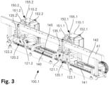
- the Figure 3 shows an oblique view of one side of the support device with two wheel carriers.
- the test bench 1 comprises two parallel inlet rails 61, 62. Their height is fixed, while one of the inlet rails 61 is adjustable in the transverse direction and the other is also fixed in the transverse direction.
- the bogie 50 is moved into the test position of the test stand 1 on the inlet rails 61, 62.
- the bogie 50 comprises a bogie frame 51 on which the wheel axles 54 with the wheels 55 of the bogie 50 are mounted via secondary springs 52 and wheel bearings 53 with primary suspension.
- the test bench 1 comprises a portal 20 with two supports 21, 22, on which a cross member 25 is mounted so as to be movable vertically along a linear guide.
- Each of the supports 21, 22 consists of two vertical supports 21.1, 21.2; 22.1, 22.2, which are arranged parallel to one another.
- the outer ends of the cross member 25 move in the space between the respective vertical supports 21.1, 21.2; 22.1, 22.2.
- the linear guide comprises vertical rails and a carriage which can be moved on each of them and to which the cross member 25 is attached.
- a drive motor for a spindle is arranged on each of the carriages.
- the two spindles run horizontally inwards from the respective carriage, parallel to the cross member 25, and are used for the transverse adjustment of two load application units 30.1, 30.2 arranged on the cross member 25 via a further linear guide.
- the load application units 30.1, 30.2 are constructed identically.
- the stroke of the cross member 25 on the supports 21, 22 is approximately 1,000 mm, so that the load application units 30.1, 30.2 can work together with different bogies and reference measuring cells for calibration.
- the load application units 30.1, 30.2 each comprise a device for generating a downward-directed basic force.
- This can be hydraulic or electric load cylinders in a manner known per se or preferably a hybrid system with a double-acting hydraulic cylinder, the cylinder chambers of which are supplied with hydraulic fluid by a bi-directional axial piston pump, as in the pending international patent application PCT/EP 2020/085560 of 10 December 2020 described.
- the corresponding piston rods have transmission pieces which interact with corresponding action points on the bogie 50 to transmit an impact force.
- the action points are located longitudinally in the middle of the bogie frame and in Transverse direction in a plane which is approximately defined by the centre of the treads of the wheels of the corresponding side.
- the cross member 25 further comprises a supply arrangement 28 with drag chains for supplying the load application units 30.1, 30.2 with electrical energy and control signals. Sensor signals from sensors arranged on the load application units 30.1, 30.2 are also transmitted to a control and/or evaluation station via the drag chains of the supply arrangement 28.
- the test bench 1 further comprises a support device 100 with four wheel carriers 110.1, 110.2, 110.3, 110.4, whereby two wheel carriers 110.1, 110.2 interact with the first inlet rail 61 and two wheel carriers 110.3, 110.4 interact with the second inlet rail 62.
- a side 100.1 of the support device 100 is shown.
- Each wheel carrier 110.1, 110.2, 110.3, 110.4 comprises a lifting unit 120.1, 120.2 and a wheel support unit 150.1, 150.2 arranged thereon (cf. Figure 3 ).
- the lifting unit 120.1, 120.2 is described below in connection with the Figures 4-6 described in more detail. It has, among other things, a platform 135.1, 135.2 at its upper end, on which the respective wheel receiving unit 150.1, 150.2 is mounted.
- the wheel receiving unit 150.1, 150.2 has two rotating rollers 151.1, 152.1; 151.2, 152.2, which can be set in rotation by a servo motor. Their axes of rotation run horizontally and perpendicular to the inlet rail 61.
- the wheel receiving unit 150.1, 150.2 also has a centering mechanism 155.1, 155.2 with a plunger which is essentially located between the rollers 151.1, 152.1; 151.2, 152.2 and can be moved by another servo motor via a planetary gear and a spindle drive along a linear axis parallel to the rotation axes of the rollers 151.1, 152.1; 151.2, 152.2.
- Each lifting unit 120.1, 120.2 comprises two linear slides 121.1, 122.1; 121.2, 122.2, which are movably mounted on a linear guide 140 parallel to the inlet rail 61.
- the linear guide 140 comprises two parallel profile rails 141, 142.
- a rack 145 is arranged parallel to these.
- Each of the linear slides 121.1, 121.2 carries a pinion driven by a drive motor, which cooperates with the rack 145 to move the respective linear slide 121.1, 121.2 along the Linear guide 140.
- the other linear slide 122.1, 122.2 of the lifting unit 120.1, 120.2 is mechanically connected to the first linear slide 121.1, 121.2 via a spindle. This is explained further below in connection with the Figures 4-6 described in more detail.
- the forces exerted on the bogie 50 by the two load application units 30.1, 30.2 can be controlled independently of one another. Both symmetrical and asymmetrical forces can thus be exerted on the bogie 50 in the transverse direction.
- the reaction of the bogie 50 to the acting forces can be recorded using suitable, known measuring devices.
- the Figure 4 shows an oblique view of the lifting unit of a wheel carrier
- the Figure 5 a cross-sectional view of the lifting unit in the lowered position
- the Figure 6 an oblique view of the lifting unit in the raised state.
- the lifting unit 120 comprises two linear slides 121, 122. These each have a carrier 123, 124, on the underside of which two guide carriages 125.1, 125.2; 126.1, 126.2 are mounted. These each comprise several ball raceways, which, when the wheel carrier is mounted, are in contact with the running surfaces of the respective profile rail (cf. Figure 3 ) work together.
- a drive motor 131 is arranged on the outer end face of the carrier 123 of one of the linear slides 121. This is a servo motor with a vertically oriented drive axis. The latter acts on a pinion 133 via a planetary gear 132. This meshes with the rack running parallel to the linear guide (see. Figure 3 ).
- the drive motor 131 is designed such that the output rotates essentially freely when the motor is de-energized.
- a further drive motor 127 is arranged on the carrier 124 of the other linear slide 122. This is again a servo motor, but its drive axis is oriented horizontally and runs longitudinally in the middle of the carrier 124.
- the drive motor 127 acts via a planetary gear 128 on a spindle 129.1 of a ball screw drive 129.
- the latter comprises a rotatable but axially immovable Threaded sleeve 129.4, which interacts with the external thread of the spindle 129.1, so that the distance between the two linear slides 121, 122 can be adjusted by means of the drive motor 127.
- Two levers 134.1...8 of equal length are articulated on the side surfaces of the supports 123, 124 via corresponding pivot bearings arranged at a horizontal distance.
- the levers are articulated on the platform 135 in bearings arranged laterally at the same horizontal distance, so that a total of four four-bar linkages 136.1, 136.2, 136.3, 136.4 are formed.
- two vertically oriented cylindrical guide pins 137.1, 137.2 are arranged as well as three measuring cells 138.1, 138.2, 138.3 spanning a triangle.
- the latter are designed as shear beam measuring cells.
- the force introduction points are each located near the side edge of the platform 135, the introduction point of the first measuring cell 138.1 is arranged centrally in the longitudinal direction, the introduction points of the other measuring cells 138.2, 138.3 are arranged near the longitudinal ends of the platform 135, so that the best possible force distribution is achieved.
- the Figures 4 and 5 show the lifting unit 120 in the lowered state, ie the two linear slides 121, 122 are at their maximum distance, and the platform 135 is minimally removed from the plane defined by the linear slides 121, 122.
- the lifting unit 120 is shown in the maximum raised state.
- the distance between the linear slides 121, 122 is smaller, and the distance of the platform 135 from the plane is greater due to the lever mechanism with the four four-bar linkages 136.1...4.
- the height of the platform 135 can thus be adjusted by operating the drive motor 127, with the maximum stroke being approximately 80 mm.
- the lifting unit 120 can also be positioned as a whole along the linear guide (ie parallel to the inlet rails) with the aid of the drive motor 131.
- the Figure 7 shows an oblique view to illustrate the interaction of an inlet rail and the wheel receiving device of the wheel carrier with a running wheel of the bogie.
- the wheel support unit 150 of the wheel carrier 110 is positioned on the platform 135. It rests on the three measuring cells and is guided by the two guide bolts 137.1, 137.2.
- the wheel support unit 150 has two openings on its underside that are slightly larger than the cross-section of the guide bolts 137.1, 137.2 that they hold.
- Disc springs are also used to fix the wheel support unit 150 with its openings relative to the guide bolts 137.1, 137.2.
- the Figure 8 shows an oblique view of the test stand 1 with the bogie 50 in the test position. In this position, vertical forces can be exerted on the bogie 50 using the load application units 30.1, 30.2. Forces exerted by the wheels 55 of the bogie 50 on the wheel carriers 110 are measured in recorded in a known manner, transmitted to an evaluation device and evaluated there.
- the device according to the invention can also be used to simulate the insertion of shim plates. To do this, the wheel carriers where the insertion of a shim plate is to be simulated are raised further. As soon as a balanced load distribution is achieved, the thickness of the required shims can be calculated from the additional lifting. A torsion test is also possible by raising the wheel carriers to different heights.
- the device according to the invention enables simple calibration of the measuring cells and/or the load-acting units by aligning the corresponding wheel carrier and a load-acting unit with one another and inserting a reference measuring cell between the load-acting unit and the wheel carrier. The system can then be loaded using the load-acting unit, with the forces acting being measured by the reference measuring cell and the measuring cells.
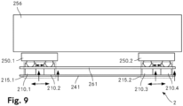
- the Figure 9 is a schematic drawing of a further embodiment of the test bench according to the invention. This corresponds in many respects to the previously described embodiment.
- the test bench 2 according to the further embodiment is used to test the torsion of two bogies 250.1, 250.2 attached to a car body 256.
- the car to be tested is moved on the inlet rails 261 to the wheel carriers 210.1, 210.2, 210.3, 210.4 and is gripped by them as described above.
- the force acting on the bogies 250.1, 250.2 is provided by the car body 256 itself.
- the torsion is caused by a different height setting of the wheel carriers 210.1, 210.2, 210.3, 210.4 (and the other four wheel carriers arranged in a mirror image on the other side).
- the test bench 2 can be easily adapted to the dimensions of the bogies 250.1, 250.2 and the car body 256.
- the distances between the wheel carriers 210.1, 210.2; 210.3, 210.4 of the respective wheel carrier group 215.1, 215.2 are adjusted and, on the other hand, the distance between the two wheel carrier groups 215.1, 215.2 is adjusted by moving the wheel carriers 210.1...4 along the corresponding profile rail 241.
- the invention is not limited to the embodiments shown, as long as it does not deviate from the scope of the claims.
- test bench can be chosen differently, depending in particular on the bogies to be tested. For bogies with more than four wheels, additional wheel carriers can be present.
- the invention provides a test bench for testing bogies which has a simple construction.
Landscapes
- Physics & Mathematics (AREA)
- General Physics & Mathematics (AREA)
- Testing Of Devices, Machine Parts, Or Other Structures Thereof (AREA)
- Handcart (AREA)
- A Measuring Device Byusing Mechanical Method (AREA)
Claims (20)
- Support de roue (110.1, 110.2), destiné à porter une roue placée sur un boggie (250.1, 250.2), le support de roue (110.1, 110.2) comprenant une unité de levage (120.1, 120.2) présentant les composants suivants :- une plateforme (135.1, 135.2) ;- un premier chariot linéaire (121.1, 121.2), qui est déplaçable le long d'un guidage linéaire (140), s'étendant dans une direction de déplacement à la perpendiculaire de la direction d'action ;caractérisé en ce que l'unité de levage comprend par ailleurs les composants suivants:- un deuxième chariot linéaire (122.1, 122.2), qui est déplaçable dans la direction de déplacement, le long du guidage linéaire (140) ;- un premier mécanisme à levier, destiné à accoupler le premier chariot linéaire (121.1, 121.2) avec la plateforme (135.1, 135.2) ; et- un deuxième mécanisme à levier, destiné à accoupler le deuxième chariot linéaire (122.1, 122.2) avec la plateforme (135.1, 135.2),un écart entre le premier chariot linéaire (121.1, 121.2) et le deuxième chariot linéaire (122.1, 122.2) étant variable, de sorte qu'un écart entre la plateforme (135.1, 135.2) et le premier chariot linéaire (121.1, 121.2) et le deuxième chariot linéaire (122.1, 122.2) dans la direction d'action soit variable.
- Support de roue (110.1, 110.2) selon la revendication 1, caractérisé en ce que le premier mécanisme à levier comprend deux quadrilatères articulés (136.1, 136.2) et en ce que le deuxième mécanisme à levier comprend deux quadrilatères articulés (136.3, 136.4) supplémentaires, les axes de levier de tous les leviers (134.1, ...8) des quadrilatères articulés (136.1, 136.2, 136.3, 136.4) s'étendant à la parallèle les uns des autre et à la perpendiculaire de la direction de déplacement.
- Support de roue (110.1, 110.2) selon la revendication 2, caractérisé en ce que les deux quadrilatères articulés (136.1, 136.2) du premier mécanisme à levier sont écartés l'un de l'autre dans une direction des axes de levier et en ce que les deux quadrilatères articulés (136.3, 136.4) du deuxième mécanisme à levier sont écartés l'un de l'autre dans une direction des axes de levier.
- Support de roue (110.1, 110.2) selon l'une quelconque des revendications 1 à 3, caractérisé en ce que le premier chariot linéaire (121.1, 121.2) et le deuxième chariot linéaire (122.1, 122.2) sont assemblés mécaniquement par un système destiné à ajuster leur écart mutuel.
- Support de roue (110.1, 110.2) selon la revendication 4, caractérisé en ce que le système destiné à ajuster l'écart comprenda) une broche filetée, logée en rotation et de manière indéplaçable en direction axiale sur l'un des chariots linéaires (121, 122), dont l'axe de rotation s'étend dans la direction de déplacement etb) un entraîneur rotatif, qui est placé sur l'autre des chariots linéaires (122, 121).
- Support de roue (110.1, 110.2) selon la revendication 5, caractérisé en ce que la broche filetée et l'entraîneur forment une vis à billes (129).
- Support de roue (110. 1, 110.2) selon l'une quelconque des revendications 1 à 6, caractérisé en ce que sur le premier chariot linéaire (121.1, 121.2) est placé un moteur d'entraînement (131) dont la prise de force agit sur un pignon (133), pour déplacer le premier chariot linéaire (121.1, 121.2), le pignon (133) interagissant avec une crémaillère (145) qui s'étend dans la direction de déplacement.
- Banc d'essai (1), destiné à tester des boggies (250.1, 250.2) de wagons ferroviaires, comprenant un dispositif de support (100), destiné à porter un boggie (250.1, 250.2) pendant un processus de test, comprenant plusieurs supports de roue (110.1, 110.2) pour porter chacun une roue placée sur le boggie (250. 1, 250.2), le support de roue (110.1, 110.2) comprenant une unité de levage (120.1, 120.2), présentant les composants suivants :- une plateforme (135.1, 135.2) ;- un premier chariot linéaire (121.1, 121.2), qui est déplaçable le long d'un guidage linéaire (140), s'étendant dans une direction de déplacement à la perpendiculaire de la direction d'action ;caractérisé en ce que l'unité de levage comprend par ailleurs les composants suivants:- un deuxième chariot linéaire (122.1, 122.2), qui est déplaçable dans la direction de déplacement, le long du guidage linéaire (140) ;- une premier mécanisme à levier, destiné à accoupler le premier chariot linéaire (121.1, 121.2) avec la plateforme (135.1, 135.2) ; et- un deuxième mécanisme à levier, destiné à accoupler le deuxième chariot linéaire (122.1, 122.2) avec la plateforme (135.1, 135.2),un écart entre le premier chariot linéaire (121.1, 121.2) et le deuxième chariot linéaire (122.1, 122.2) étant variable, de sorte qu'un écart entre la plateforme (135.1, 135.2) et le premier chariot linéaire (121.1, 121.2) et le deuxième chariot linéaire (122.1, 122.2) dans la direction d'action soit variable.
- Banc d'essai (1) selon la revendication 8, comprenant une unité d'action de charge, destinée à générer une charge d'action linéaire sur le boggie (250.1, 250.2), comprenant une unité de génération de force destinée à générer une force fondamentale et un système de transmission, destiné à transmettre la force fondamentale dans la force d'action orientée dans une direction d'action, agissant sur le boggie (250.1, 250.2).
- Banc d'essai (1) selon la revendication 8, caractérisé en ce que le dispositif de support (100) comprend au moins huit supports de roue selon la revendication 1, destinés à porter toutes les roues d'au moins deux boggies (250.1, 250.2) placés sur un châssis de wagon.
- Banc d'essai (1) selon l'une quelconque des revendications 8 à 10, caractérisé par deux rails d'entrée (61, 62), placés à la parallèle, s'étendant dans la direction de déplacement, destinés à amener le boggie (250.1, 250.2) qui doit être mesuré.
- Banc d'essai (1) selon la revendication 11, caractérisé en ce que le guidage linéaire (140) et les rails d'entrée (61, 62) sont placés de telle sorte que des systèmes récepteurs de roue (150, 150.1, 150.2) placés sur les plateformes (135) des supports de roue (110.1, 110.2) soient déplaçables par un mouvement vertical de la plateforme (135.1, 135.2) concernée entre une position d'engagement et une position de libération, dans la position d'engagement, des forces étant transmissibles dans la direction de déplacement, entre le système récepteur de roue (150, 150.1, 150.2) concerné et la roue concernée, alors que dans la position de libération, le support de roue (110.1, 110.2) est librement mobile dans la direction de déplacement, par rapport au boggie (250.1, 250.2).
- Banc d'essai (1) selon l'une quelconque des revendications 8 à 12, caractérisé en ce que chacun des supports de roue (110. 1, 110.2) comprend un système récepteur de roue (150, 150.1, 150.2) placé sur la plateforme (135.1, 135.2), ainsi qu'une unité de mesure de la force, destinée à mesurer une force exercée sur le système récepteur de roue (150, 150. 1, 150.2).
- Procédé, destiné à tester un boggie (250.1, 250.2) d'un wagon ferroviaire, comprenant les étapes suivantes, consistant à :a) faire entrer le boggie (250.1, 250.2) le long d'une direction de déplacement, en ce que des boudins de roues placées sur le boggie (250.1, 250.2) roulent sur deux rails d'entrée (61, 62) parallèles ;
caractérisé parb) le positionnement les uns par rapport aux autres du boggie (250.1, 250.2) et de plusieurs supports de roue (110.1, 110.2) d'un dispositif de support (100) le long de la direction de déplacement, de sorte qu'à chacune des roues soit associé un support de roue (110.1, 110.2), chacun des supports de roue (110.1, 110.2) comprenant une unité de levage (120.1, 120.2) pourvue d'une plateforme (135.1, 135.2), d'un premier chariot linéaire (121.1, 121.2), qui est déplaçable le long d'un guidage linéaire (140) s'étendant dans la direction de déplacement, d'un deuxième chariot linéaire (122.1, 122.2), qui est déplaçable le long du guidage linéaire (140) dans la direction de déplacement, d'un premier mécanisme à levier, destiné à accoupler le premier chariot linéaire (121.1, 121.2) avec la plateforme (135.1, 135.2) et d'un deuxième mécanisme à levier, destiné à accoupler le deuxième chariot linéaire (122.1, 122.2) avec la plateforme (135.1, 135.2);c) la saisie du boggie (250.1, 250.2), par réduction d'un écart entre le premier chariot linéaire (121.1, 121.2) et le deuxième chariot linéaire (122.1, 122.2) des unités de levage (120.1, 120.2), de telle sorte que les supports de roue (110.1, 110.2) soient relevés et saisissent les roues dans la zone de leur surface de roulement ;d) le relèvement des boggies (250.1, 250.2), jusqu'à ce que les boudins de roues soient relevés des rails d'entrée (61, 62) ;e) le test des boggies (250.1, 250.2), par l'exercice d'une force d'action linéaire sur le boggie (250.1, 250.2), la force d'action linéaire étant disposée à la perpendiculaire de la direction de déplacement et la mesure des forces agissant sur les supports de roue (110.1, 110.2). - Procédé selon la revendication 14, caractérisé en ce que pour le test des boggies (250.1, 250.2), tous les chariots linéaires (121, 122) sont librement mobiles dans la direction de déplacement, alors que les écarts entre le premier chariot linéaire (121.1, 121.2) et le deuxième chariot linéaire (122.1, 122.2) de chaque fois un support de roues (110) sont fixés.
- Procédé selon la revendication 15, caractérisé en ce que sur chaque support de roue (110.1, 110.2) est placé sur le premier chariot linéaire (121.1, 121.2) un moteur d'entraînement (131) dont la prise de force agit sur un pignon (133), pour déplacer le premier chariot linéaire (121.1, 121.2), le pignon (133) interagissant avec une crémaillère qui s'étend dans la direction de déplacement, pour tester le boggie (250.1, 250.2), le pignon (133) étant libéré en rotation libre, notamment par mise hors tension d'un moteur d'entraînement (131) électrique pour le pignon (133).
- Procédé selon l'une quelconque des revendications 14 à 16, caractérisé en ce que par un réglage individuel des hauteurs des supports de roue (110.1, 110.2), l'on simule l'insertion de rondelles plates.
- Procédé selon l'une quelconque des revendications 14 à 17, caractérisé par l'étape supplémentaire consistant à positionner le boggie (250.1, 250.2) par un déplacement des support de roue (110.1, 110.2) le long de la direction de déplacement, dans une position d'action permettant l'action d'une force, suite à quoi, la force d'action linéaire est exercée au moyen de l'unité d'action de force.
- Procédé selon l'une quelconque des revendications 14 à 17, caractérisé en ce que deux boggies (250.1, 250.2) sont placés sur un châssis de wagon et en ce que toutes les roues des deux boggies (250.1, 250.2) sont réceptionnées simultanément par des supports de roue (110) correspondants, suite à quoi a lieu un test de voilage, par le réglage de différentes hauteurs des supports de roue (110.1, 110.2), la force d'action linéaire étant exercée au moyen d'un poids propre du châssis de wagon.
- Procédé selon la revendication 19, caractérisé par l'étape supplémentaire consistant à régler un écart entre deux groupes de supports de roue (110) par rapport à un écart entre les boggies (250.1, 250.2) sur le châssis de wagon.
Applications Claiming Priority (2)
| Application Number | Priority Date | Filing Date | Title |
|---|---|---|---|
| PCT/EP2020/087793 WO2022135711A1 (fr) | 2020-12-23 | 2020-12-23 | Banc d'essai pour l'essai de bogies de véhicules ferroviaires |
| PCT/EP2021/086008 WO2022136066A1 (fr) | 2020-12-23 | 2021-12-15 | Porte-moyeu pour porter une roue montée sur un bogie, et banc d'essai pour tester des bogies de véhicules ferroviaires |
Publications (3)
| Publication Number | Publication Date |
|---|---|
| EP4267932A1 EP4267932A1 (fr) | 2023-11-01 |
| EP4267932B1 true EP4267932B1 (fr) | 2025-02-19 |
| EP4267932C0 EP4267932C0 (fr) | 2025-02-19 |
Family
ID=74141567
Family Applications (1)
| Application Number | Title | Priority Date | Filing Date |
|---|---|---|---|
| EP21840500.9A Active EP4267932B1 (fr) | 2020-12-23 | 2021-12-15 | Porte-moyeu pour porter une roue montée sur un bogie, et banc d'essai pour tester des bogies de véhicules ferroviaires |
Country Status (6)
| Country | Link |
|---|---|
| US (1) | US12510440B2 (fr) |
| EP (1) | EP4267932B1 (fr) |
| CN (1) | CN116648611A (fr) |
| AU (1) | AU2021408391A1 (fr) |
| TW (1) | TWI807549B (fr) |
| WO (2) | WO2022135711A1 (fr) |
Families Citing this family (8)
| Publication number | Priority date | Publication date | Assignee | Title |
|---|---|---|---|---|
| WO2022122162A1 (fr) * | 2020-12-10 | 2022-06-16 | Nencki Ag | Banc d'essai pour tester des bogies de véhicules ferroviaires |
| CN115638943A (zh) * | 2022-10-25 | 2023-01-24 | 中车长春轨道客车股份有限公司 | 激振试验台及激振试验装置 |
| CN115824677B (zh) * | 2022-11-28 | 2025-08-08 | 武汉中车株机轨道交通装备有限公司 | 一种城轨轮对跑合试验台 |
| CN115753159B (zh) * | 2023-01-03 | 2025-09-09 | 中车株洲电力机车有限公司 | 一种齿轨转向架动态性能试验台及试验方法 |
| EP4610618A1 (fr) * | 2024-03-01 | 2025-09-03 | Baker Hughes Holdings LLC | Systèmes et procédés d'inspection de roue de train |
| CN118837127B (zh) * | 2024-09-04 | 2025-04-01 | 梁山华盛交通设备制造有限公司 | 一种挂车牵引测试装置及方法 |
| US20260104323A1 (en) * | 2024-10-16 | 2026-04-16 | Officine Meccaniche B.B.M. S.p.A. | Testing device for a railway bogie |
| CN120594062B (zh) * | 2025-08-07 | 2025-10-21 | 太行国家实验室 | 一种抗互扰两通道静力加载装置 |
Family Cites Families (22)
| Publication number | Priority date | Publication date | Assignee | Title |
|---|---|---|---|---|
| DE3604186A1 (de) * | 1986-02-10 | 1987-08-13 | Fraunhofer Ges Forschung | Verfahren und einrichtung zur pruefung von schienenfahrzeugraedern unter betriebsaehnlichen belastungsbedingungen |
| US5629476A (en) * | 1995-04-21 | 1997-05-13 | Sondey; Thomas F. | Modular fluid manifold system |
| US5600059A (en) * | 1995-04-21 | 1997-02-04 | Sondey; Thomas F. | Engine delivery system |
| US5864065A (en) * | 1997-11-25 | 1999-01-26 | Amsted Industries Incorporated | Test apparatus for a railway wheel |
| DE102004021488B4 (de) * | 2003-06-04 | 2006-06-01 | Windhoff Bahn- Und Anlagentechnik Gmbh | Prüfstand für Drehgestelle und/oder Radsätze von Schienenfahrzeugen |
| DE102006051725A1 (de) * | 2006-10-30 | 2008-05-08 | Schenck Process Gmbh | Verfahren und Vorrichtung zum Positionieren eines Prüflings in einem Prüfstand für Drehgestelle von Schienenfahrzeugen |
| DE102009002678B4 (de) * | 2009-04-27 | 2012-04-26 | AGG Anlagen- und Gerätebau GmbH | Prüfverfahren für Drehgestelle sowie Prüf- und Montagestand |
| DE102011100207B4 (de) * | 2011-05-02 | 2014-08-21 | Schenck Process Gmbh | Verfahren zum Prüfen eines Drehgestells eines Schienenfahrzeugs sowie Prüfstand für ein Drehgestell eines Schienenfahrzeugs |
| US8596125B2 (en) * | 2011-06-23 | 2013-12-03 | Amsted Rail Company, Inc. | Railway wheel ultrasonic testing apparatus |
| US8596126B2 (en) * | 2011-07-19 | 2013-12-03 | Amsted Rail Company, Inc. | Method and apparatus for a railway wheel ultrasonic testing apparatus |
| CZ2012125A3 (cs) * | 2012-02-21 | 2013-08-28 | VÚKV a.s. | Zkusební stav pro stacionární zkousky kolejových vozidel a zpusob merení na zkusebním stavu |
| CN103267648B (zh) * | 2013-05-23 | 2016-03-02 | 西南交通大学 | 铁道车辆转向架蛇行运动实验台 |
| CN104627899B (zh) * | 2015-02-04 | 2017-06-30 | 黄骅 | 剪式升降台 |
| CN205241153U (zh) * | 2015-11-04 | 2016-05-18 | 铜陵科达车辆装备有限责任公司 | 一种用于铁路轮对磨合试验的升降装置 |
| CN105628410B (zh) * | 2016-03-31 | 2019-03-01 | 吉林大学 | 高速轮轨关系可靠性试验台 |
| CN106080664A (zh) * | 2016-08-24 | 2016-11-09 | 北京主导时代科技有限公司 | 一种双机器人轮辋轮辐探伤系统 |
| CN207829544U (zh) * | 2017-12-28 | 2018-09-07 | 郑州科技学院 | 基于plc的新型智能立体车库 |
| CN110849642A (zh) * | 2019-12-19 | 2020-02-28 | 株洲壹星科技股份有限公司 | 一种转向架空载试验装置 |
| CN111366385B (zh) * | 2020-05-06 | 2024-05-07 | 吉林大学 | 一种适用于变轨性能研究的双驱动轮变轨机构 |
| TW202212793A (zh) * | 2020-05-08 | 2022-04-01 | 日商國際計測器股份有限公司 | 車輪測試裝置 |
| WO2022122162A1 (fr) * | 2020-12-10 | 2022-06-16 | Nencki Ag | Banc d'essai pour tester des bogies de véhicules ferroviaires |
| US20220268651A1 (en) * | 2021-02-22 | 2022-08-25 | Diversified Products, LLC | Dynamometer For Use With Rail Equipment, And Systems And Methods Of Using Same |
-
2020
- 2020-12-23 WO PCT/EP2020/087793 patent/WO2022135711A1/fr not_active Ceased
-
2021
- 2021-12-15 EP EP21840500.9A patent/EP4267932B1/fr active Active
- 2021-12-15 CN CN202180087035.1A patent/CN116648611A/zh active Pending
- 2021-12-15 WO PCT/EP2021/086008 patent/WO2022136066A1/fr not_active Ceased
- 2021-12-15 US US18/269,294 patent/US12510440B2/en active Active
- 2021-12-15 AU AU2021408391A patent/AU2021408391A1/en active Pending
- 2021-12-22 TW TW110148080A patent/TWI807549B/zh active
Also Published As
| Publication number | Publication date |
|---|---|
| AU2021408391A1 (en) | 2023-06-29 |
| WO2022135711A1 (fr) | 2022-06-30 |
| WO2022136066A1 (fr) | 2022-06-30 |
| AU2021408391A9 (en) | 2025-03-13 |
| US12510440B2 (en) | 2025-12-30 |
| US20240085277A1 (en) | 2024-03-14 |
| TWI807549B (zh) | 2023-07-01 |
| TW202227307A (zh) | 2022-07-16 |
| CN116648611A (zh) | 2023-08-25 |
| EP4267932A1 (fr) | 2023-11-01 |
| EP4267932C0 (fr) | 2025-02-19 |
Similar Documents
| Publication | Publication Date | Title |
|---|---|---|
| WO2022136066A1 (fr) | Porte-moyeu pour porter une roue montée sur un bogie, et banc d'essai pour tester des bogies de véhicules ferroviaires | |
| DE102009002678B4 (de) | Prüfverfahren für Drehgestelle sowie Prüf- und Montagestand | |
| DE3823764C2 (de) | Prüfstand zum Prüfen eines Achsenaufbaus eines Nutzfahrzeugs | |
| DE112009000488B4 (de) | Testsystem mit Strebenanordnung sowie Verfahren | |
| DE112009000493B4 (de) | Testsystem sowie Verfahren zum Testen eines Fahrzeugs | |
| EP3077784B1 (fr) | Ensemble et procédé d'essai de mécanismes de manoeuvre d'aiguilles | |
| DE102004021488B4 (de) | Prüfstand für Drehgestelle und/oder Radsätze von Schienenfahrzeugen | |
| DE102013219471A1 (de) | Kraftfahrzeugprüfsystem | |
| EP3668684B1 (fr) | Dispositif et procédé pour l'usinage simultané de plusieurs essieux montés d'un véhicule ferroviaire | |
| EP3137872A1 (fr) | Banc d'essai à rouleaux et procédé permettant de faire fonctionner un banc d'essai à rouleaux | |
| EP1836018A1 (fr) | Machine pour faire tourner des paires de roues souterraine, utilisee dans le traitement de paires de roues pour des vehicules sur rails | |
| DE10212255A1 (de) | Straßensimulationsprüfstand | |
| DE102011100207B4 (de) | Verfahren zum Prüfen eines Drehgestells eines Schienenfahrzeugs sowie Prüfstand für ein Drehgestell eines Schienenfahrzeugs | |
| DE10118682A1 (de) | Prüfeinrichtung zur Kraftfahrzeug-Crashsimulation | |
| DE2355317A1 (de) | Klemmgeraet fuer eine einseil-umlaufbahn | |
| DE69619057T2 (de) | Plattenzirkulator und Apparat zur Kraftmessung | |
| DE102012013525B4 (de) | Prüfvorrichtung für einen Prüfradsatz für ein Schienenfahrzeug | |
| DE102004063041A1 (de) | Fahrzeugfunktionsprüfstand | |
| DE202023002212U1 (de) | Hochdynamischer Pulsator zur Federwegsimulation bei Gelenkwellenprüfständen | |
| EP4433794A1 (fr) | Procédé de positionnement d'un véhicule sur un banc d'essai de véhicules | |
| DE102004023730A1 (de) | Fahrzeugprüfstand | |
| DE2321012A1 (de) | Vorrichtung und verfahren zum messen und einstellen der radaufhaengung von kraftfahrzeugen | |
| AT526858B1 (de) | Fahrzeugträger für einen Prüfstand und Verfahren zur Rüstung eines Prüfstandes mit einem derartigen Fahrzeugträger | |
| DE2005048C3 (de) | Vorrichtung zur Festlegung der Bezugslage zum Gleis eines MeB- oder Überwachungssystems | |
| HK40092560A (zh) | 用於支撑设置在转向架上的车轮的车轮托架和用於测试轨道车辆转向架的测试台 |
Legal Events
| Date | Code | Title | Description |
|---|---|---|---|
| STAA | Information on the status of an ep patent application or granted ep patent |
Free format text: STATUS: UNKNOWN |
|
| STAA | Information on the status of an ep patent application or granted ep patent |
Free format text: STATUS: THE INTERNATIONAL PUBLICATION HAS BEEN MADE |
|
| PUAI | Public reference made under article 153(3) epc to a published international application that has entered the european phase |
Free format text: ORIGINAL CODE: 0009012 |
|
| STAA | Information on the status of an ep patent application or granted ep patent |
Free format text: STATUS: REQUEST FOR EXAMINATION WAS MADE |
|
| 17P | Request for examination filed |
Effective date: 20230524 |
|
| AK | Designated contracting states |
Kind code of ref document: A1 Designated state(s): AL AT BE BG CH CY CZ DE DK EE ES FI FR GB GR HR HU IE IS IT LI LT LU LV MC MK MT NL NO PL PT RO RS SE SI SK SM TR |
|
| DAV | Request for validation of the european patent (deleted) | ||
| DAX | Request for extension of the european patent (deleted) | ||
| GRAP | Despatch of communication of intention to grant a patent |
Free format text: ORIGINAL CODE: EPIDOSNIGR1 |
|
| STAA | Information on the status of an ep patent application or granted ep patent |
Free format text: STATUS: GRANT OF PATENT IS INTENDED |
|
| INTG | Intention to grant announced |
Effective date: 20240930 |
|
| GRAS | Grant fee paid |
Free format text: ORIGINAL CODE: EPIDOSNIGR3 |
|
| GRAA | (expected) grant |
Free format text: ORIGINAL CODE: 0009210 |
|
| STAA | Information on the status of an ep patent application or granted ep patent |
Free format text: STATUS: THE PATENT HAS BEEN GRANTED |
|
| AK | Designated contracting states |
Kind code of ref document: B1 Designated state(s): AL AT BE BG CH CY CZ DE DK EE ES FI FR GB GR HR HU IE IS IT LI LT LU LV MC MK MT NL NO PL PT RO RS SE SI SK SM TR |
|
| REG | Reference to a national code |
Ref country code: GB Ref legal event code: FG4D Free format text: NOT ENGLISH |
|
| REG | Reference to a national code |
Ref country code: CH Ref legal event code: EP |
|
| REG | Reference to a national code |
Ref country code: DE Ref legal event code: R096 Ref document number: 502021006729 Country of ref document: DE |
|
| REG | Reference to a national code |
Ref country code: IE Ref legal event code: FG4D Free format text: LANGUAGE OF EP DOCUMENT: GERMAN |
|
| U01 | Request for unitary effect filed |
Effective date: 20250220 |
|
| U07 | Unitary effect registered |
Designated state(s): AT BE BG DE DK EE FI FR IT LT LU LV MT NL PT RO SE SI Effective date: 20250228 |
|
| PG25 | Lapsed in a contracting state [announced via postgrant information from national office to epo] |
Ref country code: RS Free format text: LAPSE BECAUSE OF FAILURE TO SUBMIT A TRANSLATION OF THE DESCRIPTION OR TO PAY THE FEE WITHIN THE PRESCRIBED TIME-LIMIT Effective date: 20250519 |
|
| PG25 | Lapsed in a contracting state [announced via postgrant information from national office to epo] |
Ref country code: PL Free format text: LAPSE BECAUSE OF FAILURE TO SUBMIT A TRANSLATION OF THE DESCRIPTION OR TO PAY THE FEE WITHIN THE PRESCRIBED TIME-LIMIT Effective date: 20250219 |
|
| PG25 | Lapsed in a contracting state [announced via postgrant information from national office to epo] |
Ref country code: ES Free format text: LAPSE BECAUSE OF FAILURE TO SUBMIT A TRANSLATION OF THE DESCRIPTION OR TO PAY THE FEE WITHIN THE PRESCRIBED TIME-LIMIT Effective date: 20250219 |
|
| PG25 | Lapsed in a contracting state [announced via postgrant information from national office to epo] |
Ref country code: IS Free format text: LAPSE BECAUSE OF FAILURE TO SUBMIT A TRANSLATION OF THE DESCRIPTION OR TO PAY THE FEE WITHIN THE PRESCRIBED TIME-LIMIT Effective date: 20250619 Ref country code: NO Free format text: LAPSE BECAUSE OF FAILURE TO SUBMIT A TRANSLATION OF THE DESCRIPTION OR TO PAY THE FEE WITHIN THE PRESCRIBED TIME-LIMIT Effective date: 20250519 |
|
| PG25 | Lapsed in a contracting state [announced via postgrant information from national office to epo] |
Ref country code: HR Free format text: LAPSE BECAUSE OF FAILURE TO SUBMIT A TRANSLATION OF THE DESCRIPTION OR TO PAY THE FEE WITHIN THE PRESCRIBED TIME-LIMIT Effective date: 20250219 |
|
| PG25 | Lapsed in a contracting state [announced via postgrant information from national office to epo] |
Ref country code: GR Free format text: LAPSE BECAUSE OF FAILURE TO SUBMIT A TRANSLATION OF THE DESCRIPTION OR TO PAY THE FEE WITHIN THE PRESCRIBED TIME-LIMIT Effective date: 20250520 |
|
| PG25 | Lapsed in a contracting state [announced via postgrant information from national office to epo] |
Ref country code: SM Free format text: LAPSE BECAUSE OF FAILURE TO SUBMIT A TRANSLATION OF THE DESCRIPTION OR TO PAY THE FEE WITHIN THE PRESCRIBED TIME-LIMIT Effective date: 20250219 |
|
| PG25 | Lapsed in a contracting state [announced via postgrant information from national office to epo] |
Ref country code: CZ Free format text: LAPSE BECAUSE OF FAILURE TO SUBMIT A TRANSLATION OF THE DESCRIPTION OR TO PAY THE FEE WITHIN THE PRESCRIBED TIME-LIMIT Effective date: 20250219 |
|
| PG25 | Lapsed in a contracting state [announced via postgrant information from national office to epo] |
Ref country code: SK Free format text: LAPSE BECAUSE OF FAILURE TO SUBMIT A TRANSLATION OF THE DESCRIPTION OR TO PAY THE FEE WITHIN THE PRESCRIBED TIME-LIMIT Effective date: 20250219 |
|
| PLBE | No opposition filed within time limit |
Free format text: ORIGINAL CODE: 0009261 |
|
| STAA | Information on the status of an ep patent application or granted ep patent |
Free format text: STATUS: NO OPPOSITION FILED WITHIN TIME LIMIT |
|
| REG | Reference to a national code |
Ref country code: CH Ref legal event code: L10 Free format text: ST27 STATUS EVENT CODE: U-0-0-L10-L00 (AS PROVIDED BY THE NATIONAL OFFICE) Effective date: 20251231 |
|
| REG | Reference to a national code |
Ref country code: CH Ref legal event code: U11 Free format text: ST27 STATUS EVENT CODE: U-0-0-U10-U11 (AS PROVIDED BY THE NATIONAL OFFICE) Effective date: 20260101 |
|
| PGFP | Annual fee paid to national office [announced via postgrant information from national office to epo] |
Ref country code: GB Payment date: 20251219 Year of fee payment: 5 |
|
| 26N | No opposition filed |
Effective date: 20251120 |
|
| U20 | Renewal fee for the european patent with unitary effect paid |
Year of fee payment: 5 Effective date: 20251230 |
|
| PGFP | Annual fee paid to national office [announced via postgrant information from national office to epo] |
Ref country code: CH Payment date: 20260101 Year of fee payment: 5 |