EP4268691A2 - Insert pour friteuse comprenant un panier de friteuse - Google Patents
Insert pour friteuse comprenant un panier de friteuse Download PDFInfo
- Publication number
- EP4268691A2 EP4268691A2 EP23170648.2A EP23170648A EP4268691A2 EP 4268691 A2 EP4268691 A2 EP 4268691A2 EP 23170648 A EP23170648 A EP 23170648A EP 4268691 A2 EP4268691 A2 EP 4268691A2
- Authority
- EP
- European Patent Office
- Prior art keywords
- frying
- shaft
- basket
- insert
- fried
- Prior art date
- Legal status (The legal status is an assumption and is not a legal conclusion. Google has not performed a legal analysis and makes no representation as to the accuracy of the status listed.)
- Pending
Links
Images


Classifications
-
- A—HUMAN NECESSITIES
- A47—FURNITURE; DOMESTIC ARTICLES OR APPLIANCES; COFFEE MILLS; SPICE MILLS; SUCTION CLEANERS IN GENERAL
- A47J—KITCHEN EQUIPMENT; COFFEE MILLS; SPICE MILLS; APPARATUS FOR MAKING BEVERAGES
- A47J37/00—Baking; Roasting; Grilling; Frying
- A47J37/12—Deep fat fryers, e.g. for frying fish or chips
- A47J37/1223—Deep fat fryers, e.g. for frying fish or chips with means for filtering the frying liquid
-
- A—HUMAN NECESSITIES
- A47—FURNITURE; DOMESTIC ARTICLES OR APPLIANCES; COFFEE MILLS; SPICE MILLS; SUCTION CLEANERS IN GENERAL
- A47J—KITCHEN EQUIPMENT; COFFEE MILLS; SPICE MILLS; APPARATUS FOR MAKING BEVERAGES
- A47J37/00—Baking; Roasting; Grilling; Frying
- A47J37/12—Deep fat fryers, e.g. for frying fish or chips
- A47J37/1276—Constructional details
- A47J37/1285—Valves or arrangements to drain used oil or food particles settled at the bottom of the frying vessel
-
- A—HUMAN NECESSITIES
- A47—FURNITURE; DOMESTIC ARTICLES OR APPLIANCES; COFFEE MILLS; SPICE MILLS; SUCTION CLEANERS IN GENERAL
- A47J—KITCHEN EQUIPMENT; COFFEE MILLS; SPICE MILLS; APPARATUS FOR MAKING BEVERAGES
- A47J37/00—Baking; Roasting; Grilling; Frying
- A47J37/12—Deep fat fryers, e.g. for frying fish or chips
- A47J37/1295—Frying baskets or other food holders
Definitions
- the invention relates to a frying insert for a deep fryer with a frying basket, according to the preamble of patent claim 1.
- Frying inserts with frying baskets for deep-frying food to be fried are known.
- the food to be fried such as French fries or chicken pieces
- the frying insert is hung in a frying container of a deep fryer filled with frying material and the food to be fried is fried with the deep fryer.
- the disadvantage of conventional frying inserts with frying baskets is that the food to be fried, especially a pile of food to be fried, is not fried evenly without shaking the food to be fried during frying.
- the object of the invention is therefore to provide a frying insert of the type mentioned at the beginning, with which the disadvantages mentioned can be avoided, with which fried food can be fried evenly even in an almost completely filled frying basket of the frying insert.
- the invention further relates to a method for deep-frying food to be fried in a deep fryer according to claim 7.
- the invention therefore also has the task of specifying a method of the type mentioned at the outset, with which the disadvantages mentioned can be avoided, with which fried food can be fried evenly in an almost completely filled frying basket of a frying insert.
- Fig. 1 to 5 show at least parts of preferred embodiments of a frying insert 16 for a deep fryer 1 with a frying basket 20, the frying basket 20 having a top 21 with an opening for the supply and removal of Fried food 22 in the frying basket 20 and a bottom 23 opposite the top 21 and spaced from the top 21, the frying insert 16 having at least one shaft 18 extending from the bottom 23 of the frying basket 20 towards the top 21 of the frying basket 20
- Flow channel for frying 4 comprises, wherein the shaft 18 has a lower end 24 facing the underside 23 of the frying basket 20 and an opposite upper end 25 arranged at a distance from the lower end 24 of the shaft 18, with passage openings 26 on a wall of the shaft 18
- Flows of frying material 4 are formed from the shaft 18, with a cover 19 being arranged at the upper end 25 of the shaft 18, which cover 19 covers the shaft 18 at the upper end 25.
- the frying insert 16 according to the invention is intended to be inserted into a deep fryer 1.
- a deep fryer 1 is a device for deep-frying fried foods.
- the deep fryer 1 usually has a deep frying container 2.
- the frying container 2 is a container in which a frying material 4, in particular oil or fat, is heated and in which the food to be fried 22 is fried.
- the frying container 2 can preferably be designed as a tub.
- the frying container 2 is filled with frying material 4 up to a minimum filling level.
- the surface of the fryer 4 means the surface of the fryer 4 filled in the fryer container 2.
- heating rods or one or more heating coils can be used as the heating source 3.
- a frying flow can preferably be formed in the deep fryer 1.
- the frying flow can result from convection, for example when the colder frying material 22 is introduced into the heated frying material 4.
- Preferred The fry flow can also be formed by circulating the fry 4 in the deep fryer 1, in particular by means of a pump.
- the frying insert 16 includes a frying basket 20.
- the frying basket 20 is part of the frying insert 16.
- the frying basket 20 is preferably made of metal, in particular stainless steel.
- the frying insert 16 can preferably comprise a handle 31, in particular a handle or a handle. This means that the frying insert 16 can easily be hung into the deep fryer 1.
- the handle 31 can preferably be made of a metal, in particular stainless steel.
- the handle 31 can preferably be wrapped or covered with a non- or poorly heat-conducting material, in particular a polymer.
- a non- or poorly heat-conducting material in particular a polymer.
- the handle 31 of the frying insert 16 is shown as an example.
- the frying insert 16 can preferably include an intermediate piece 32, which intermediate piece 32 connects the handle 31 to the frying basket 20.
- the intermediate piece 32 can preferably be attached to the frying basket 20 and/or to the handle 31.
- the intermediate piece 32 can preferably be designed in several parts.
- the intermediate piece can preferably be made of metal, in particular stainless steel.
- Fig. 1 the intermediate piece 32 of the frying insert 16 is shown as an example.
- the frying basket 20 has a top 21 with an opening.
- the fried food 22 can be placed in the frying basket 20 and removed again after frying.
- the fried food 22 is preferably fed or introduced into the frying basket 20 through the opening.
- 22 French fries can be placed or arranged in the frying basket 20 through the opening as food to be fried.
- Fig. 1 a sectional view of a first preferred embodiment of the frying insert 16 is shown, with French fries arranged in the frying basket 20 as an example are shown.
- the reference number 22 points to a French fries shown as an example.
- the frying basket 20 has an underside 23 which is opposite the top 21 and spaced apart from the top 21.
- the top 21 and the bottom 23 of the frying basket 20 are in Fig. 1 visible.
- the top 21 preferably points upwards and the underside 23 points downwards, so that the food to be fried 22 is held in the frying basket 20 during frying.
- the frying insert 16 comprises at least one shaft 18 extending from the underside 23 of the frying basket 20 towards the top 21 of the frying basket 20 as a flow channel for the frying door 4.
- at least one shaft 18, which is open at the bottom, extends upwards from the underside 23 of the frying basket 20. In this way, the fryer 4 can pass through the shaft 18 unhindered into those areas of the frying insert 16, so that uniform frying of a pile of fried food 22 is possible.
- the shaft 18 has a lower end 24, which lower end 24 faces the underside 23 of the frying basket 20, and an upper end 25, which upper end 25 is arranged opposite and spaced from the lower end 24 of the shaft 18. having.
- the two ends, i.e. the lower end 24 and the upper end 25, are exemplary in the Figs. 2 and 3 shown.
- the shaft 18 can preferably be open at the lower end 24, particularly when it is not installed in the frying basket 20. This is exemplified in Fig. 2 shown.
- the shaft 18 can be manufactured easily, since, for example, only a perforated plate has to be formed into a cylinder, in particular bent and welded, then provided with a cover 19, and finally arranged on an already known frying basket 20 of a frying insert 16 or .must be attached.
- already known frying baskets can be designed particularly easily to form the frying insert 16 according to the invention.
- the shaft 18, which is open at the lower end 24, can also preferably be formed during the production of the frying basket 20.
- passage openings 26 for the flow of fry 4 from the shaft 18 are formed on a wall of the shaft 18. This is exemplified in the Fig. 1 and 2 shown.
- the passage openings 26 can preferably be designed as drill holes.
- the shaft 18 can preferably be formed from a perforated sheet metal.
- the passage openings 26 can preferably have a diameter of at least 2 mm, particularly preferably at least 4 mm, in particular at least 6 mm.
- the passage openings 26 can preferably have a width and a length. It can preferably be provided that the width and/or the length is at least 2 mm, particularly preferably at least 4 mm, in particular at least 6 mm.
- the shaft 18 can preferably have at least 8, particularly preferably at least 16, in particular at least 32, passage openings 26.
- the wall of the shaft 18 is designed as a grid 27.
- the at least one shaft 18 can preferably be formed from a grid 27.
- the fried food 22 can be kept away from the inside of the shaft 18, while the frying material 4 can penetrate through the walls to the outside.
- a particularly good and in particular evenly distributed flow of the fryer 4 coming from the shaft 18 to the fried food 22 can be achieved. Due to this evenly distributed flow through the grid 27, the fryer 4 can fry the food 22 of a fully filled frying basket 20 particularly evenly, which also reduces the frying time.
- the grid 27 can preferably have a mesh size of at least 2 mm, particularly preferably at least 3 mm, in particular at least 4 mm.
- the wall of the shaft 18 can preferably also be referred to as a shaft wall.
- the shaft wall of the shaft 18 can preferably be designed as a grid 27, in particular from a grid 27.
- the at least one shaft 18 can preferably have a substantially rectangular cross section.
- the shaft 18 can have four side surfaces, with the passage openings 26 being formed on the side surfaces, in particular evenly distributed on all four side surfaces.
- the at least one shaft 18 can have a substantially circular cross section.
- the shaft 18 can be essentially cylindrical, with the passage openings 26 being arranged on the lateral surface of the cylinder.
- the height 28 of the shaft 18 is smaller than the height 29 of the frying basket 20.
- a particularly good flow of the frying material 4 laterally out of the shaft 18 can be achieved when the food 22 is being fried.
- the height 29 of the frying basket 20 is preferably the length between the bottom 23 of the frying basket 20 and the top 21 of the frying basket 20. In Fig. 1 the height 29 of the frying basket 20 is shown as an example.
- a cover 19 is arranged at the upper end 25 of the shaft 18, which cover 19 covers the shaft 18 at the upper end 25.
- the shaft 18 includes the cover 19.
- the cover 19 is in particular part of the shaft 18.
- the cover 19 can preferably cover the shaft 18 at the top. Concealed can also be referred to in particular as closed.
- the cover 19 can completely close the shaft 18 at the upper end 25. Due to the cover 19, the fryer 4 cannot leave the shaft 18 upwards unhindered, but is deflected laterally into the fried food 22.
- Cover 19 is preferably designed in such a way that the upper end 25 of the shaft 18 is completely closed or covered.
- the cover 19 can preferably also be referred to as a cover for the shaft 18.
- the cover 19 is preferably made of metal, in particular stainless steel.
- the cover 19 is preferably a metal lid.
- the height 28 of the shaft 18 is preferably the length between the lower end 24 of the shaft 18 to an upper side of the cover 19, which cover 19 is arranged at the upper end 25 of the shaft 18.
- the height 28 of the shaft 18 is shown as an example.
- the at least one shaft 18 ends at a middle height of the frying basket 20.
- the average height of the frying basket 20 can be an area which extends from the middle of the height towards the top 21 of the frying basket 20 and the bottom 23 of the frying basket 20.
- the area can extend at least 10%, in particular at least 20%, of a measured height 29 of the frying basket 20 in the direction of the top 21 of the frying basket 20 and the bottom 23 of the frying basket 20. This allows a particularly effective flow to be formed through the shaft 18 and through the passage openings 26, whereby the individual parts of a pile of fried food 22 can be fried particularly evenly.
- a pile of fried food 22 is in particular a lot of things lying on top of each other, like some French fries.
- a pile of fried food 22 can, for example, be present in a substantially completely filled frying basket 20. This is exemplified in Fig. 1 with the fried food 22 shown as French fries.
- the fried food 22 or the French fries are not part of the frying insert 16, but are in Fig. 1 shown merely to illustrate the heap.
- the at least one shaft 18 can extend at least a quarter, preferably at least half, in particular at least two thirds, of the height 29 of the frying basket 20 from the bottom 23 of the frying basket 20 towards the top 21 of the frying basket 20.
- the at least one shaft 18 is arranged evenly spaced from at least two opposite walls 30 of the frying basket 20.
- the at least one shaft 18 can be arranged in particular centrally within the frying basket 20.
- the frying basket 20 can preferably have four walls 30, with two of the four walls 30 being arranged opposite one another and at a distance from one another.
- the walls 30 of the frying basket 20 are shown as an example on a frying basket 20 with a rectangular base.
- two shafts 18 are shown as an example, which are arranged evenly spaced from two opposite walls 30 of the frying basket 20.
- the frying basket 20 can have a width, a length and a height 29.
- the height 29 of the frying basket 20 can be at least 10 cm, particularly preferably at least 15 cm, in particular at least 20 cm.
- the width of the frying basket 20 can be at least 10 cm, particularly preferably at least 15 cm, in particular at least 20 cm.
- the length of the frying basket 20 can be at least 20 cm, particularly preferably at least 30 cm, in particular at least 40 cm.
- the frying basket 20, in particular from the bottom 23 of the frying basket 20 to the top 21 of the frying basket 20, can have a substantially circular cross section.
- the diameter of the cross section of the frying basket 20 can preferably be at least 10 cm, particularly preferably at least 20 cm, in particular at least 30 cm.
- the frying insert 16 in particular the frying basket 20, has several shafts 18.
- the frying insert 16 has at least two, preferably at least three, in particular at least four, shafts 18. This makes it possible to achieve particularly uniform frying of the food 22 to be fried, particularly with larger frying inserts 16.
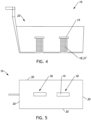
- a second preferred embodiment of the frying insert 16 is shown in a sectional view, with two shafts 18, which are designed as grids 27, being shown as an example.
- Fig. 5 further shows the in Fig. 4 Shown preferred embodiment of the frying insert 16 in plan view.
- the at least two, preferably at least three, in particular at least four, shafts 18 can each be arranged evenly spaced from at least two opposite walls 30 of the frying basket 20.
- a food 22 to be fried such as those in., is placed into the frying basket 20 of the frying insert 16 Fig. 1 French fries shown were added.
- the frying basket 20 can in particular be completely filled with the food to be fried 22.
- the frying insert 16 is then inserted into a deep fryer 1.
- the frying insert 16 is preferably inserted into the frying container 2 of the deep fryer 1 filled with frying material 4 in such a way that at least the cover 19 is arranged below the frying material surface. This ensures that the fryer 4 first flows through the shaft 18 and the passage openings 26, then flows through the fried food 22, i.e. the French fries, whereby the fried food 22 is fried evenly.
- the frying insert 16 is removed from the deep fryer 1 and then the fried food 22 is removed from the frying insert 16, in particular the frying basket 20.
- a frying flow is formed in the frying container 2 of the deep fryer 1 during the frying of the food 22 to be fried.
- the frying material 4 When frying the food 22, the frying material 4 preferably flows into the shaft 18 through the lower end 24 of the shaft 18 and leaves the shaft 18 through the passage openings 26.
- the frying flow preferably flows at least partially through the shaft 18 and through the passage openings 26 to the fried food 22.
- the frying insert 16 according to the invention is particularly suitable in conjunction with the deep fryer 1 with a frying circuit, since the pump in the frying circuit creates a particularly strong flow.
- a deep fryer 1 with the frying circuit is exemplified in Fig. 6 shown.
- the frying insert 16 according to the invention can also be used and advantageous in conventional deep fryers 1 without the frying circuit.
- the frying insert 16 is therefore not limited to the use of the deep fryer 1 with the frying circuit, but can be used on different deep fryers 1, in particular on differently designed deep fryers 1.
- Fig. 6 shows at least parts of a preferred embodiment of a deep fryer 1 for reducing pollutants in fried goods 22, comprising at least one deep frying container 2, at least one heating source 3 arranged in and/or on the deep frying container 2, at least one frying circuit and at least one pump for pumping the frying container 4 in the frying circuit, wherein the at least one frying circuit comprises a frying line 5 connected to the frying container 2, at least one filter system 6 connected to the frying line 5 and at least one frying return line 7 connected to the filter system 6 and the frying container 2, the frying return line 7 being connected to the frying container 2 is connected to a bottom 8 of the frying container 2, and that the bottom 8 is designed to slope down to an outlet of the frying return line 7.
- a method for reducing pollutants in fried foods 22 comprising the frying system, with frying material 4 being heated in the frying container 2, with frying goods 22 arranged in a frying insert 16 being fried, with frying material 4 being diverted into the frying cycle through the frying outlet 5 and is cleaned by means of the filter system 6, with cleaned frying 4 being returned to the frying container 2 via the frying return line 7, the frying container 2 having a bottom 8 sloping towards the outlet of the frying return line 7, whereby frying residues 17 from the bottom 8 of the frying container 2 through the returned cleaned fryer 4 is carried along and washed to the surface of the fryer 4 by the fryer flow generated.
- the frying return line 7 is connected to the frying container 2 at the bottom 8 of the frying container 2, and the bottom 8 is designed to slope down to the outlet of the frying return line 7, frying residues 17 are carried away from the bottom 8 by the returned frying stream and onto the frying surface washed away, from which they can be separated.
- a cold zone and water deposits in a cold zone are thereby avoided and the absence of the cold zone greatly reduces the formation of acrylamide, as a result of which the fried goods 22 are less contaminated with acrylamides.
- the fryer 4 has to be changed less often and the fryer 4 is constantly cleaned.
Landscapes
- Engineering & Computer Science (AREA)
- Food Science & Technology (AREA)
- Frying-Pans Or Fryers (AREA)
Applications Claiming Priority (1)
| Application Number | Priority Date | Filing Date | Title |
|---|---|---|---|
| ATA50290/2022A AT525986B1 (de) | 2022-04-29 | 2022-04-29 | Fritteuse zur reduktion von schadstoffen in frittiergütern |
Publications (2)
| Publication Number | Publication Date |
|---|---|
| EP4268691A2 true EP4268691A2 (fr) | 2023-11-01 |
| EP4268691A3 EP4268691A3 (fr) | 2023-11-08 |
Family
ID=86282305
Family Applications (2)
| Application Number | Title | Priority Date | Filing Date |
|---|---|---|---|
| EP23724213.6A Pending EP4514186A1 (fr) | 2022-04-29 | 2023-04-28 | Friteuse destinée à réduire des substances toxiques dans des produits à frire |
| EP23170648.2A Pending EP4268691A3 (fr) | 2022-04-29 | 2023-04-28 | Insert pour friteuse comprenant un panier de friteuse |
Family Applications Before (1)
| Application Number | Title | Priority Date | Filing Date |
|---|---|---|---|
| EP23724213.6A Pending EP4514186A1 (fr) | 2022-04-29 | 2023-04-28 | Friteuse destinée à réduire des substances toxiques dans des produits à frire |
Country Status (4)
| Country | Link |
|---|---|
| US (1) | US20250288154A1 (fr) |
| EP (2) | EP4514186A1 (fr) |
| AT (1) | AT525986B1 (fr) |
| WO (1) | WO2023209176A1 (fr) |
Family Cites Families (8)
| Publication number | Priority date | Publication date | Assignee | Title |
|---|---|---|---|---|
| US3910548A (en) * | 1971-05-19 | 1975-10-07 | Baskettes Ltd | Means for making potato baskets |
| US4502373A (en) * | 1983-03-25 | 1985-03-05 | Keating Richard T | Cleaning system for deep fryer |
| US4508027A (en) * | 1983-12-19 | 1985-04-02 | Mccord Frederick B | Portion dividing frying basket |
| US6095037A (en) * | 1996-09-27 | 2000-08-01 | Pitco Frialator, Inc. | High efficient convection fryer with continuous filtration |
| WO2001021051A1 (fr) * | 1999-09-21 | 2001-03-29 | Nockemann, Bernd | Procede de friture de produits a frire et dispositif correspondant |
| DE102005039052A1 (de) * | 2005-04-08 | 2006-10-12 | Hartmann, Rainer, Dr.-Ing. | Fritteuse |
| US20070137497A1 (en) * | 2005-11-04 | 2007-06-21 | Savage Steven J | Convection fryer with convenient filter and oil treatment provisions |
| US20080213446A1 (en) * | 2007-03-01 | 2008-09-04 | Feinberg Bruce G | Automated fryer refilling device and method |
-
2022
- 2022-04-29 AT ATA50290/2022A patent/AT525986B1/de active
-
2023
- 2023-04-28 WO PCT/EP2023/061295 patent/WO2023209176A1/fr not_active Ceased
- 2023-04-28 EP EP23724213.6A patent/EP4514186A1/fr active Pending
- 2023-04-28 EP EP23170648.2A patent/EP4268691A3/fr active Pending
- 2023-04-28 US US18/860,465 patent/US20250288154A1/en active Pending
Also Published As
| Publication number | Publication date |
|---|---|
| AT525986B1 (de) | 2023-10-15 |
| EP4514186A1 (fr) | 2025-03-05 |
| EP4268691A3 (fr) | 2023-11-08 |
| AT525986A4 (de) | 2023-10-15 |
| US20250288154A1 (en) | 2025-09-18 |
| WO2023209176A1 (fr) | 2023-11-02 |
Similar Documents
| Publication | Publication Date | Title |
|---|---|---|
| DE2731338C2 (de) | Verfahren und Vorrichtung zum Garen von Lebensmitteln | |
| DE3432246A1 (de) | Fettbackgeraet | |
| EP4268691A2 (fr) | Insert pour friteuse comprenant un panier de friteuse | |
| DE69927175T2 (de) | Verfahren und vorrichtung zum zubereiten von eiern auf verschiedener weise | |
| WO2019081267A1 (fr) | Plaque de four pour aliments | |
| DE2832659A1 (de) | Maschine zum kochen von teigwaren, reis und sonstigen lebensmittelerzeugnissen | |
| DE202010000494U1 (de) | Vorrichtung zur Aufbereitung von Pökellake | |
| EP0958772A2 (fr) | Dispositif à retenir des aliments pendant la cuisson dans une fondue | |
| WO2001065946A1 (fr) | Recipient a treillis de mailles ou element de support a treillis de mailles, destine au faconnage ou a l'accueil de produits alimentaires, notamment de produits carnes et de saucisses | |
| DE102005014738B4 (de) | Gargutaufnahmevorrichtung für Heissluftdämpfer | |
| DE3905990C2 (fr) | ||
| AT520675B1 (de) | Einsatz für eine fritteuse | |
| EP0771165B1 (fr) | Panier utilise dans un four a air chaud pour la preparation d'aliments | |
| EP0659379B1 (fr) | Friteuse | |
| DE102020201328B3 (de) | Fritteuse | |
| DE9100126U1 (de) | Vorrichtung zum Entfernen von Rechen- und/oder Siebgut aus einem Gerinne strömender Flüssigkeit | |
| DE102005025164A1 (de) | Gargutaufnahmevorrichtung für flache Brat- und Grillstücke | |
| DE202012001428U1 (de) | Vorrichtung zum Halten mehrerer zuzubereitender Fische | |
| DE1567382C3 (de) | Vorrichtung zur Gewinnung von Stärke | |
| DE60000291T2 (de) | Kochvorrichtung | |
| EP4216777A1 (fr) | Dispositif pour faire cuire et/ou faire frire un produit à cuire | |
| EP1579795A1 (fr) | Récipient pour frire | |
| DE29804145U1 (de) | Gerät zum Herstellen von Spätzle | |
| DE9301422U1 (de) | Kochgerät | |
| DE202015105084U1 (de) | Fritteuse nach Art einer Durchlauffritteuse |
Legal Events
| Date | Code | Title | Description |
|---|---|---|---|
| PUAI | Public reference made under article 153(3) epc to a published international application that has entered the european phase |
Free format text: ORIGINAL CODE: 0009012 |
|
| STAA | Information on the status of an ep patent application or granted ep patent |
Free format text: STATUS: THE APPLICATION HAS BEEN PUBLISHED |
|
| PUAL | Search report despatched |
Free format text: ORIGINAL CODE: 0009013 |
|
| AK | Designated contracting states |
Kind code of ref document: A2 Designated state(s): AL AT BE BG CH CY CZ DE DK EE ES FI FR GB GR HR HU IE IS IT LI LT LU LV MC ME MK MT NL NO PL PT RO RS SE SI SK SM TR |
|
| AK | Designated contracting states |
Kind code of ref document: A3 Designated state(s): AL AT BE BG CH CY CZ DE DK EE ES FI FR GB GR HR HU IE IS IT LI LT LU LV MC ME MK MT NL NO PL PT RO RS SE SI SK SM TR |
|
| RIC1 | Information provided on ipc code assigned before grant |
Ipc: A47J 37/12 20060101AFI20231004BHEP |
|
| STAA | Information on the status of an ep patent application or granted ep patent |
Free format text: STATUS: REQUEST FOR EXAMINATION WAS MADE |
|
| 17P | Request for examination filed |
Effective date: 20240508 |
|
| RBV | Designated contracting states (corrected) |
Designated state(s): AL AT BE BG CH CY CZ DE DK EE ES FI FR GB GR HR HU IE IS IT LI LT LU LV MC ME MK MT NL NO PL PT RO RS SE SI SK SM TR |