EP4268697A1 - Lave-vaisselle - Google Patents
Lave-vaisselle Download PDFInfo
- Publication number
- EP4268697A1 EP4268697A1 EP21911335.4A EP21911335A EP4268697A1 EP 4268697 A1 EP4268697 A1 EP 4268697A1 EP 21911335 A EP21911335 A EP 21911335A EP 4268697 A1 EP4268697 A1 EP 4268697A1
- Authority
- EP
- European Patent Office
- Prior art keywords
- nozzle
- dishwasher
- wash
- sensing module
- magnetic force
- Prior art date
- Legal status (The legal status is an assumption and is not a legal conclusion. Google has not performed a legal analysis and makes no representation as to the accuracy of the status listed.)
- Pending
Links
Images




Classifications
-
- A—HUMAN NECESSITIES
- A47—FURNITURE; DOMESTIC ARTICLES OR APPLIANCES; COFFEE MILLS; SPICE MILLS; SUCTION CLEANERS IN GENERAL
- A47L—DOMESTIC WASHING OR CLEANING; SUCTION CLEANERS IN GENERAL
- A47L15/00—Washing or rinsing machines for crockery or tableware
- A47L15/0018—Controlling processes, i.e. processes to control the operation of the machine characterised by the purpose or target of the control
- A47L15/0049—Detection or prevention of malfunction, including accident prevention
-
- A—HUMAN NECESSITIES
- A47—FURNITURE; DOMESTIC ARTICLES OR APPLIANCES; COFFEE MILLS; SPICE MILLS; SUCTION CLEANERS IN GENERAL
- A47L—DOMESTIC WASHING OR CLEANING; SUCTION CLEANERS IN GENERAL
- A47L15/00—Washing or rinsing machines for crockery or tableware
- A47L15/0018—Controlling processes, i.e. processes to control the operation of the machine characterised by the purpose or target of the control
- A47L15/0021—Regulation of operational steps within the washing processes, e.g. optimisation or improvement of operational steps depending from the detergent nature or from the condition of the crockery
- A47L15/0028—Washing phases
-
- A—HUMAN NECESSITIES
- A47—FURNITURE; DOMESTIC ARTICLES OR APPLIANCES; COFFEE MILLS; SPICE MILLS; SUCTION CLEANERS IN GENERAL
- A47L—DOMESTIC WASHING OR CLEANING; SUCTION CLEANERS IN GENERAL
- A47L15/00—Washing or rinsing machines for crockery or tableware
- A47L15/14—Washing or rinsing machines for crockery or tableware with stationary crockery baskets and spraying devices within the cleaning chamber
- A47L15/18—Washing or rinsing machines for crockery or tableware with stationary crockery baskets and spraying devices within the cleaning chamber with movably-mounted spraying devices
- A47L15/22—Rotary spraying devices
- A47L15/23—Rotary spraying devices moved by means of the sprays
-
- A—HUMAN NECESSITIES
- A47—FURNITURE; DOMESTIC ARTICLES OR APPLIANCES; COFFEE MILLS; SPICE MILLS; SUCTION CLEANERS IN GENERAL
- A47L—DOMESTIC WASHING OR CLEANING; SUCTION CLEANERS IN GENERAL
- A47L15/00—Washing or rinsing machines for crockery or tableware
- A47L15/42—Details
- A47L15/4214—Water supply, recirculation or discharge arrangements; Devices therefor
- A47L15/4219—Water recirculation
-
- A—HUMAN NECESSITIES
- A47—FURNITURE; DOMESTIC ARTICLES OR APPLIANCES; COFFEE MILLS; SPICE MILLS; SUCTION CLEANERS IN GENERAL
- A47L—DOMESTIC WASHING OR CLEANING; SUCTION CLEANERS IN GENERAL
- A47L15/00—Washing or rinsing machines for crockery or tableware
- A47L15/42—Details
- A47L15/4251—Details of the casing
- A47L15/4257—Details of the loading door
-
- A—HUMAN NECESSITIES
- A47—FURNITURE; DOMESTIC ARTICLES OR APPLIANCES; COFFEE MILLS; SPICE MILLS; SUCTION CLEANERS IN GENERAL
- A47L—DOMESTIC WASHING OR CLEANING; SUCTION CLEANERS IN GENERAL
- A47L15/00—Washing or rinsing machines for crockery or tableware
- A47L15/42—Details
- A47L15/4251—Details of the casing
- A47L15/4274—Arrangement of electrical components, e.g. control units or cables
-
- A—HUMAN NECESSITIES
- A47—FURNITURE; DOMESTIC ARTICLES OR APPLIANCES; COFFEE MILLS; SPICE MILLS; SUCTION CLEANERS IN GENERAL
- A47L—DOMESTIC WASHING OR CLEANING; SUCTION CLEANERS IN GENERAL
- A47L15/00—Washing or rinsing machines for crockery or tableware
- A47L15/42—Details
- A47L15/4278—Nozzles
- A47L15/428—Rotary nozzles
-
- A—HUMAN NECESSITIES
- A47—FURNITURE; DOMESTIC ARTICLES OR APPLIANCES; COFFEE MILLS; SPICE MILLS; SUCTION CLEANERS IN GENERAL
- A47L—DOMESTIC WASHING OR CLEANING; SUCTION CLEANERS IN GENERAL
- A47L15/00—Washing or rinsing machines for crockery or tableware
- A47L15/42—Details
- A47L15/4278—Nozzles
- A47L15/4282—Arrangements to change or modify spray pattern or direction
-
- A—HUMAN NECESSITIES
- A47—FURNITURE; DOMESTIC ARTICLES OR APPLIANCES; COFFEE MILLS; SPICE MILLS; SUCTION CLEANERS IN GENERAL
- A47L—DOMESTIC WASHING OR CLEANING; SUCTION CLEANERS IN GENERAL
- A47L15/00—Washing or rinsing machines for crockery or tableware
- A47L15/42—Details
- A47L15/44—Devices for adding cleaning agents; Devices for dispensing cleaning agents, rinsing aids or deodorants
-
- A—HUMAN NECESSITIES
- A47—FURNITURE; DOMESTIC ARTICLES OR APPLIANCES; COFFEE MILLS; SPICE MILLS; SUCTION CLEANERS IN GENERAL
- A47L—DOMESTIC WASHING OR CLEANING; SUCTION CLEANERS IN GENERAL
- A47L15/00—Washing or rinsing machines for crockery or tableware
- A47L15/42—Details
- A47L15/50—Racks ; Baskets
- A47L15/504—Arrangements for changing the height of racks
-
- A—HUMAN NECESSITIES
- A47—FURNITURE; DOMESTIC ARTICLES OR APPLIANCES; COFFEE MILLS; SPICE MILLS; SUCTION CLEANERS IN GENERAL
- A47L—DOMESTIC WASHING OR CLEANING; SUCTION CLEANERS IN GENERAL
- A47L2401/00—Automatic detection in controlling methods of washing or rinsing machines for crockery or tableware, e.g. information provided by sensors entered into controlling devices
- A47L2401/24—Spray arms status, e.g. detection of spray arm rotation
-
- A—HUMAN NECESSITIES
- A47—FURNITURE; DOMESTIC ARTICLES OR APPLIANCES; COFFEE MILLS; SPICE MILLS; SUCTION CLEANERS IN GENERAL
- A47L—DOMESTIC WASHING OR CLEANING; SUCTION CLEANERS IN GENERAL
- A47L2401/00—Automatic detection in controlling methods of washing or rinsing machines for crockery or tableware, e.g. information provided by sensors entered into controlling devices
- A47L2401/30—Variation of electrical, magnetical or optical quantities
-
- A—HUMAN NECESSITIES
- A47—FURNITURE; DOMESTIC ARTICLES OR APPLIANCES; COFFEE MILLS; SPICE MILLS; SUCTION CLEANERS IN GENERAL
- A47L—DOMESTIC WASHING OR CLEANING; SUCTION CLEANERS IN GENERAL
- A47L2401/00—Automatic detection in controlling methods of washing or rinsing machines for crockery or tableware, e.g. information provided by sensors entered into controlling devices
- A47L2401/34—Other automatic detections
-
- A—HUMAN NECESSITIES
- A47—FURNITURE; DOMESTIC ARTICLES OR APPLIANCES; COFFEE MILLS; SPICE MILLS; SUCTION CLEANERS IN GENERAL
- A47L—DOMESTIC WASHING OR CLEANING; SUCTION CLEANERS IN GENERAL
- A47L2501/00—Output in controlling method of washing or rinsing machines for crockery or tableware, i.e. quantities or components controlled, or actions performed by the controlling device executing the controlling method
- A47L2501/01—Water supply, e.g. opening or closure of the water inlet valve
-
- A—HUMAN NECESSITIES
- A47—FURNITURE; DOMESTIC ARTICLES OR APPLIANCES; COFFEE MILLS; SPICE MILLS; SUCTION CLEANERS IN GENERAL
- A47L—DOMESTIC WASHING OR CLEANING; SUCTION CLEANERS IN GENERAL
- A47L2501/00—Output in controlling method of washing or rinsing machines for crockery or tableware, i.e. quantities or components controlled, or actions performed by the controlling device executing the controlling method
- A47L2501/04—Water pressure or flow rate
-
- A—HUMAN NECESSITIES
- A47—FURNITURE; DOMESTIC ARTICLES OR APPLIANCES; COFFEE MILLS; SPICE MILLS; SUCTION CLEANERS IN GENERAL
- A47L—DOMESTIC WASHING OR CLEANING; SUCTION CLEANERS IN GENERAL
- A47L2501/00—Output in controlling method of washing or rinsing machines for crockery or tableware, i.e. quantities or components controlled, or actions performed by the controlling device executing the controlling method
- A47L2501/05—Drain or recirculation pump, e.g. regulation of the pump rotational speed or flow direction
-
- A—HUMAN NECESSITIES
- A47—FURNITURE; DOMESTIC ARTICLES OR APPLIANCES; COFFEE MILLS; SPICE MILLS; SUCTION CLEANERS IN GENERAL
- A47L—DOMESTIC WASHING OR CLEANING; SUCTION CLEANERS IN GENERAL
- A47L2501/00—Output in controlling method of washing or rinsing machines for crockery or tableware, i.e. quantities or components controlled, or actions performed by the controlling device executing the controlling method
- A47L2501/20—Spray nozzles or spray arms
-
- A—HUMAN NECESSITIES
- A47—FURNITURE; DOMESTIC ARTICLES OR APPLIANCES; COFFEE MILLS; SPICE MILLS; SUCTION CLEANERS IN GENERAL
- A47L—DOMESTIC WASHING OR CLEANING; SUCTION CLEANERS IN GENERAL
- A47L2501/00—Output in controlling method of washing or rinsing machines for crockery or tableware, i.e. quantities or components controlled, or actions performed by the controlling device executing the controlling method
- A47L2501/26—Indication or alarm to the controlling device or to the user
Definitions
- the present disclosure relates to a dishwasher.
- Dishwashers are home appliances that spray wash water to wash targets such as cooking vessels or cooking tools and the like, to remove foreign substances remaining at the wash targets.
- a dishwasher ordinarily comprises a tub providing a wash space, a rack provided in the tub and accommodating cooking vessels, a nozzle spraying wash water to the rack, a sump storing wash water, and a wash pump supplying the washer water stored in the sump to the nozzle.
- the nozzle sprays wash water to wash targets evenly, while rotating.
- the wash targets can prevent the nozzle from rotating smoothly.
- the nozzle cannot rotate smoothly, for the reason that wash water supplied from the wash pump cannot be supplied to the nozzle smoothly, and the like. At this time, the wash targets are not washed properly by the wash water, causing deterioration in the wash performance of the dishwasher.
- the dishwasher senses the alternation of a magnetic field generated by a magnetic object that is included at both ends of a nozzle, by using a Hall sensor, to sense whether the nozzle rotates.
- the Hall sensor can sense the rotation of the nozzle, as the Hall sensor senses the alternation of the polarity of a magnet. Unless two magnets are inserted into both ends of the nozzle in a way that the polarities of the two magnets are opposite to each other, the Hall sensor cannot sense the rotation of the nozzle.
- the Hall sensor cannot sense a rotation direction and a rotation speed of the nozzle, the rotation of the nozzle cannot be controlled precisely.
- the objective of the present disclosure is to provide a dishwasher capable of sensing whether a nozzle rotates, with a single magnet that is inserted into the nozzle.
- the objective of the present disclosure is to provide a dishwasher capable of sensing a rotation direction and a rotation speed of a nozzle, to control the rotation of the nozzle precisely.
- a dishwasher of one embodiment comprises a tub having a wash space in which a wash target is accommodated, a sump disposed at a lower end of the tub and storing wash water, a wash pump supplying the wash water that is accommodated in the sump to a nozzle, a rack disposed in the wash space and storing the wash target, a nozzle disposed at a lower end of the rack, rotated by a repulsive force of the wash water supplied from the wash pump, spraying the wash water to the wash target, and having a magnetic object coupled to one end of the nozzle so that a first pole and a second pole of the magnetic object face a rotation direction of the nozzle, a sensing module comprising a Hall sensor that senses a magnetic force generated by the magnetic object generated by a rotation of the nozzle, and a controller receiving sensing results from the sensing module, and determining one or more of a rotation direction of the nozzle, a rotation speed of the nozzle and whether the nozzle rotates, based on the sensing results,
- the rack comprises a first rack disposed in an upper portion of the wash space and moving up and down
- the nozzle comprises a first nozzle disposed at a lower end of the first rack, and moving up and down together with the first rack
- the sensing module comprises a first sensing module comprising a Hall sensor that is disposed in a position corresponding to a middle end of a range in which the first nozzle moves up and down.
- a first magnetic object is coupled to one end of the first nozzle, and a first weight having weight that corresponds to weight of the first magnetic object is accommodated at the other end of the first nozzle.
- the dishwasher further comprises a door provided on one surface of the tub, and opening and closing the wash space, a dispenser disposed in one area of the door, and supplying detergents to the wash space, and a fixation bracket which is coupled to the dispenser, and on which the first sensing module is mounted.
- the rack comprises a second rack disposed in a lower portion of the wash space
- the nozzle comprises a second nozzle disposed at a lower end of the second rack
- the sensing module comprises a second sensing module coupled to one side of the sump.
- a second magnetic object is coupled to one end of the second nozzle, and a second weight having weight that corresponds to weight of the second magnetic object is accommodated at the other end of the second nozzle.
- the Hall sensor is a linear Hall sensor.
- the controller determines that a magnetic force generated by the first pole of the magnetic object is sensed in a case where an output value of the sensing module is less than a predetermined first reference value, determines that a magnetic force generated by the second pole of the magnetic object is sensed in a case where an output value of the sensing module is a predetermined second reference value or greater, and determines that a magnetic force generated by the magnetic object is not sensed in a case where an output value of the sensing module is the first reference value or greater and less than the second reference value.
- the controller determines that a rotation direction of the nozzle is a first direction, and in a case where a magnetic force generated by the magnetic object is not sensed through the sensing module and then a magnetic force generated by the second pole of the magnetic object is first sensed, the controller determines that a rotation direction of the nozzle is a second direction.
- the controller calculates a rotation speed of the nozzle by using magnetic force sensing time for which a magnetic force generated by the magnetic object is sensed through the sensing module, and magnetic force non-sensing time for which a magnetic force generated by the magnetic object is not sensed through the sensing module.
- the controller determines that the nozzle is restricted, and outputs an abnormality notification to a user in a case where the magnetic force non-sensing time is predetermined reference time or greater.
- the controller determines that the nozzle is restricted, and outputs an abnormality notification to a user, in a case where a rotation speed of the nozzle is less than a predetermined minimum rotation speed.
- the controller controls wash water supplied to the nozzle through the wash pump, based on results of comparison between a rotation speed of the nozzle and a predetermined reference rotation speed.
- the reference rotation speed is set differently depending on a rotation direction of the nozzle.
- the controller controls wash water supplied to the nozzle through the wash pump, in a case where a rotation speed of the nozzle is less than the reference rotation speed, to increase the rotation speed of the nozzle, and controls wash water supplied to the nozzle through the wash pump, in a case where a rotation speed of the nozzle is the reference rotation speed or greater, to decrease the rotation speed of the nozzle.
- a single magnet can be used to sense whether a nozzle rotates, by using a magnetic object that is coupled to one end of the nozzle and a sensing module that comprises a Hall sensor.
- a magnetic object is coupled to the nozzle so that a first pole and a second pole of the magnetic object face a rotation direction of the nozzle
- a linear Hall sensor is used as a Hall sensor, to sense a rotation direction and a rotation speed of the nozzle and precisely control the rotation of the nozzle, ensuring improvement in the performance of the dishwasher.
- first means a first component, a second component, unless stated to the contrary.
- one component can be directly on (or under) another component, and an additional component can be interposed between the two components.
- any one component can be directly connected or coupled to another component, but an additional component can be “interposed” between the two components or the two components can be “connected”, “coupled”, or “connected” by an additional component.
- each component can be provided as a single one or a plurality of ones, unless explicitly stated to the contrary.
- FIG. 1 is a perspective view showing a dishwasher of one embodiment.
- the dishwasher 100 of one embodiment may comprise a case 101 and a door 102.
- the case 101 forms the exterior of the dishwasher 100.
- the case 101 may be shaped into a cuboid one surface of which is open, and have a tub 110 therein.
- the door 102 is provided on one surface of the case 101, which is open, and opens and closes a vacant space in the case 101.
- the door 102 may be opened or closed automatically or manually.
- FIG. 2 is a perspective view showing the dishwasher of one embodiment without a case and a door.
- FIG. 3 is a cross-sectional view along line "A-A" of FIG. 1 .
- the dishwasher 100 of one embodiment comprises a tub 110, a sump 120, a wash pump 130, racks 141, 142, nozzles 151, 152, 153 and sensing modules 161, 162. Though not illustrated in the drawing, the dishwasher 100 of one embodiment comprises a controller. Additionally, the dishwasher 100 of one embodiment may further comprise a dispenser 170 and a fixation bracket 180.
- the tub 110 may be provided in the case 101, and shaped into a cuboid one surface of which is open. At this time, one surface of the tub 110, which is open, may be a surface corresponding to one surface of the case 101, which is open. Accordingly, one surface of the tub 110, which is open, may be opened and closed by the door 102. A wash space 111 in which wash targets are accommodated is formed in the tub 110.
- the sump 120 is disposed at the lower end of the tub 110.
- the sump 120 stores wash water, and collects wash water that is used to wash wash targets.
- the sump 120 connects to a drainage path 121 that guides stored wash water to the outside of the dishwasher 100.
- the sump 120 may discharge wash water out of the dishwasher 100 through the drainage path 121.
- a drainage pump 122 may discharge wash water stored in the sump 120 through the drainage path 121.
- the drainage pump 122 may comprise a drainage motor (not illustrated) that generates a rotational force. As the drainage pump 122 operates, wash water stored in the sump 120 may be discharged out of the dishwasher 100 through the drainage path 121.
- a filter 123 is disposed between the tub 110 and the sump 120, to filter contaminants included in wash water that flows into the sump 120 from the tub 110.
- the wash pump 130 may supply wash water stored in the sump 120 to the nozzles 151, 152, 153.
- the wash pump 130 may comprise a wash motor (not illustrated) that generates a rotational force. As the wash pump 130 operates, wash water stored in the sump 120 may be supplied to the nozzles 151, 152, 153.
- the wash pump 130 may operate based on an instruction that is received from the controller described hereafter.
- the racks 141, 142 are disposed in the wash space 111, and accommodates wash targets.
- the racks 141, 142 may comprise a first rack 141 and a second rack 142.
- the first rack 141 may be disposed in the upper portion of the wash space 111
- the second rack 142 may be disposed in the lower portion of the wash space 111.
- the nozzles 151, 152, 153 are disposed in the wash space 111, and spray wash water to wash targets.
- the nozzles 151, 152, 153 may comprise a first nozzle 151, a second nozzle 152 and a third nozzle 153.
- the first nozzle 151 may be disposed at the lower end of the first rack 141, and spray wash water upward. That is, the first nozzle 151 may spray wash water to wash targets accommodated in the first rack 141. In one embodiment, the first nozzle 151 may spray wash water to wash targets while rotating based on a repulsive force of wash water supplied from the sump 120.
- the second nozzle 152 may be disposed at the lower end of the second rack 142, and spray wash water upward. That is, the second nozzle 152 may spray wash water to wash targets stored in the second rack 142. In one embodiment, the second nozzle 152 may spray wash water to wash targets while rotation based on a repulsive force of wash water supplied from the sump 120.
- the third nozzle 153 may be disposed at the upper end of the first rack 141, and spray wash water downward. That is, the third nozzle 153 may spray wash water to wash targets stored in the first rack 141 and the second rack 142. In one embodiment, the third nozzle 153 may spray wash water to wash targets while the third nozzle 142 does not rotate.
- the first nozzle 151 and the second nozzle 152 spray wash water while they rotate, and the third nozzle 153 may spray wash water while it does not rotate, but are not limited thereto.
- description is provided based on one embodiment in which first nozzle 151 and second nozzle 152 of the dishwasher 100 spray wash water while they rotate, and third nozzle 153 of the dishwasher 100 sprays wash water while it does not rotate, for convenience of description.
- the sensing modules 161, 162 is disposed in an area corresponding to a range in which the nozzles 151, 152, 153 operate and comprises a Hall sensor sensing a magnetic force generated by a magnetic object.
- the sensing modules 161, 162 may comprise a first sensing module 161 and a second sensing module 163.
- FIG. 4 is a perspective view showing a first rack and a first nozzle of the dishwasher of one embodiment only.
- the first rack 141 may connect to the first nozzle 151.
- the first rack 141 may comprise height adjustment parts 141a, 141b.
- the height adjustment parts 141a, 141b allows the first rack 141 to move up and down within a predetermined operation range.
- the first nozzle 151 may connect to the first rack 141. Accordingly, the first nozzle 151 may move up and down, together with the first rack 141.
- a first magnetic object 1511 is coupled to one end of the first nozzle 151, and a first weight 1512 may be provided at the other end of the first nozzle 151.
- a detailed structure of the first nozzle 151 is described with reference to FIGS. 5 and 6 .
- FIG. 5 is a perspective view showing the first nozzle of the dishwasher of one embodiment only.
- FIG. 6 is a view showing the first nozzle of the dishwasher of one embodiment, viewed from below.
- a first magnetic object 1511 is coupled to one end of the first nozzle 151, and a first weight 1512 is accommodated at the other end of the first nozzle 151.
- the first magnetic object 1511 causes a change in a magnetic field by rotating together with the first nozzle 151, to enable the first sensing module 161 to sense a magnetic force generated by the first magnetic object 1511, as the first nozzle151 rotates.
- the first magnetic object 1511 may be a magnet.
- the first magnetic object 1511 is coupled to the first nozzle 151 in a way that a first pole and a second pole of the first magnetic object 1511 face a rotation direction of the first nozzle 151. That is, the first magnetic object 1511 is coupled to the first nozzle 151 in a way that both poles of the first magnetic object 1511 face the rotation direction of the first nozzle 151.
- the first pole may be the N pole and the second pole may be an S pole, but not limited thereto.
- the first pole may be an S pole and the second pole may be an N pole.
- FIG. 7 A structure in which the first magnetic object 1511 is coupled to the first nozzle 151 is shown in FIG. 7 .
- FIG. 7 is a view separately showing a structure in which a first magnetic object is coupled to the first nozzle, in the dishwasher of one embodiment.
- the first magnetic object 1511 may be coupled to the lower side of one end of the first nozzle 151.
- the first magnetic object 1511 may be coupled to the lower side of one end of the first nozzle 151 in a way that a first magnet 1511a is accommodated inside a first magnet case 1511b.
- the first magnetic object 1511 may be coupled to the first nozzle 151 in a way that a first pole 1511a_1 and a second pole 1511a_2 of the first magnet 1511a respectively face the rotation direction of the first nozzle 151, while the first pole 1511a_1 and the second pole 1511a_2 face in opposite directions.
- the first magnet case 1511b may have a shape corresponding to the shape of the first magnet 1511a.
- the first magnet case 1511b may have a rectangular cuboid shape to accommodate a bar magnet.
- the first weight 1512 has weight corresponding to the weight of the first magnetic object 1511. At this time, the first weight 1512 may be coupled to the lower side of the other end of the first nozzle 151.
- the first weight 1512 is disposed in the end portion of the first nozzle 151, which is opposite to the end portion of the first nozzle 151 where the first magnetic object 1511 is disposed, so that the center of gravity of the first nozzle 151 to move to the center of the first nozzle 151.
- the shake of the first nozzle 151 while rotating of the first nozzle 151 may be prevented, which may be caused by a misalignment of the center of gravity of the first nozzle 151 with the center of the first nozzle 151 due to the first magnetic object 1511 disposed at one end of the first nozzle 151.
- FIG. 8 is a view showing a structure in which a first sensing module is coupled to a dispenser through a fixation bracket, in the dishwasher of one embodiment.
- the first sensing module 161 is coupled to the lower end of the dispenser 170 through the fixation bracket 180.
- the dispenser 170 is disposed in one area of the door 102. At this time, the dispenser 170 may be disposed at the center of the upper end of the inner surface of the door 102, to allow the user to insert detergents readily. The dispenser 170 may supply detergents to the wash space 111 when the dishwasher 100 performs a process in which detergents are required.
- the fixation bracket 180 is coupled to the dispenser 170.
- One end of the fixation bracket 180 is coupled to the dispenser 170 disposed at the door 102, and the first sensing module 161 is coupled to the other end of the fixation bracket 180. Since the first sensing module 161 is coupled to the dispenser 170 through the fixation bracket 180 as described above, the first magnetic object 1511 coupled to the first nozzle 151 may approach to the first sensing module 161, as illustrated in FIG. 7 . Accordingly, the first sensing module 161 may sense a magnetic force generated by the first magnetic object 1511.
- a detailed structure of the first sensing module 161 is described with reference to FIG. 9 .
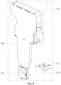
- FIG. 9 is a view separately showing the first sensing module and the fixation bracket, in the dishwasher of one embodiment.
- the first sensing module 161 is disassembled and illustrated in a perspective view.
- the first sensing module 161 may comprise a first sensing module case 1611, a first Hall sensor 1612, and a first sensing module cover 1613.
- the first sensing module case 1611 is formed in a way that the first sensing module case 1611 is directly coupled to the fixation bracket 180, and accommodates the first Hall sensor 1612.
- the first sensing module cover 1613 covers the first Hall sensor 1612 accommodated in the first sensing module case 1611, to prevent the first Hall sensor 1612 from exposed to the outside.
- the first Hall sensor 1612 senses a change in the magnetic force generated by the first magnetic object 1511.
- the first Hall sensor 1612 may be mounted on a substrate.
- the first Hall sensor 1612 may be a linear Hall sensor that can output different output values depending on the polarity of a sensed magnetic force.
- the first Hall sensor 1612 may be disposed in the meddle end of the range in which the first rack 141 and the first nozzle 151 can move up and down.
- a relationship between the position of the first nozzle 151 and the position of the first Hall sensor 1612 are described specifically with reference to FIGS. 10 and 11 .
- FIG. 10 is a view for describing a relationship between the position of the first nozzle and the position of a first Hall sensor, in the dishwasher of one embodiment.
- the first Hall sensor 1612 of the first sensing module 161 and the first nozzle 151 are viewed laterally.
- the first nozzle 151 may move to a first position A that is an upper end, a second position B that is a middle end, and a third position C that is a lower end.
- the first Hall sensor 1612 of the first sensing module 161 may move to the position corresponding to the middle of the first position A and the third position C, i.e., the second position B.
- the first Hall sensor 1612 may sense a magnetic force generated by the first magnetic object 1511, regardless of the position where the first nozzle 151 is disposed, among the first position A, the second position B and the third position C. That is, the controller may sense a magnetic force generated by the first magnetic object 1511 even if the first nozzle151 moves up and down.
- FIG. 11 is a view for describing a relationship between a rotation direction of the first nozzle and the position of a Hall sensor, in the dishwasher of one embodiment.
- the first Hall sensor 1612 of the first sensing module 161 and the first nozzle 151 are viewed from above.
- the first nozzle 151 may rotate in a first direction R1 or a second direction R2.
- the first direction R1 may be a clockwise direction
- the second direction R2 may be a counterclockwise direction.
- the first Hall sensor 1612 may first sense a magnetic force generated by the first pole 1511a_1, and then sense a magnetic force generated by the second pole 1511a_2.
- the first Hall sensor 1612 may first a magnetic force generated by the second pole 1511a_2, and then sense a magnetic force generated by the first pole 1511a_1.
- a difference in the output values based on results of sensing of the first Hall sensor 1612 is described specifically with reference to FIGs. 12 and 13 .
- FIG. 12 is a graph showing results of sensing of the first sensing module as the first nozzle rotates in a first direction, in the dishwasher of one embodiment.
- FIG. 13 is a graph showing results of sensing of the first sensing module as the first nozzle rotates in a second direction, in the dishwasher of one embodiment.
- a graph shows a change in ADC values that are output based on results of sensing of the first sensing module 161, over time.
- the first Hall sensor 1612 senses a magnetic force generated by the first pole 1511a_1 and then senses a magnetic force generated by the second pole 1511a_2.
- the first Hall sensor 1612 When the first Hall sensor 1612 senses a magnetic force generated by the first pole 1511a_1, the first Hall sensor 1612 may output a smaller value than a value output when the first Hall sensor 1612 does not sense a magnetic force generated by the first pole 1511a_1. When the first Hall sensor 1612 senses a magnetic force generated by the second pole 1511a_2, the first Hall sensor may output a larger value than a value output when the first Hall sensor 1612 dose not sense a magnetic force generated by the second pole 1511a_2.
- the controller determines that a magnetic force generated by the first pole 1511a_1 is sensed first and then a magnetic force generated by the second pole 1511a_2 is sensed, and determines that the rotation direction of the first nozzle 151 is a clockwise direction R1.
- the first Hall sensor 1612 first senses a magnetic force generated by the second pole 1511a_2 and then senses a magnetic force generated by the first pole 1511a_1.
- the controller determines that a magnetic force generated by the second pole 1511a_2 is sensed first and then a magnetic force generated by the first pole 1511a_2 is sensed, and determines that the rotation direction of the first nozzle 151 is a counterclockwise direction R2.
- FIG. 14 is a view showing a configuration disposed at the lower side of a second nozzle, in the dishwasher of one embodiment.
- the second nozzle 152 may be disposed near the lower surface of the tub 110 at the lower end of the wash space 111.
- the sump 120 is disposed in the lower portion of the tub 110.
- the second sensing module 162 is coupled to one side of the sump 120.
- the second nozzle 152 is disposed at the lower end of the second rack 142.
- a second magnetic object 1521 may be coupled to one end of the second nozzle 152, and a second weight 1522 may be provided at the other end of the second nozzle 152.
- a detailed structure of the second nozzle 152 is described with reference to FIG. 15 .
- FIG. 15 is a view showing a structure in which a magnetic object is coupled to the second nozzle, in the dishwasher of one embodiment.
- the second magnetic object 1521 is coupled to one end of the second nozzle 152.
- the second weight 1522 is accommodated at the other end of the second nozzle 152, as illustrated in FIG. 3 .
- the second weight 1522 may be accommodated in the other end of the second nozzle 152, or coupled to the lower side of the other end of the second nozzle 152 like the first weight 1512.
- the second magnetic object 1521 rotates together with the second nozzle 152 as the second nozzle 152 rotates, causing a change in a magnetic field, to enable the second sensing module 162 to sense a magnetic force generated by the second magnetic object 1521.
- the second magnetic object 1521 may be a magnet.
- FIG. 16 A structure in which the second magnetic object 1521 is coupled to the second nozzle 152 is illustrated in FIG. 16 .
- FIG. 16 is a view separately showing the structure in which the magnetic object is coupled to the second nozzle, in the dishwasher of one embodiment.
- the second magnetic object 1521 may be coupled to the lower side of one end of the second nozzle 152.
- the second magnetic object 1521 may be coupled to the lower side of one end of the second nozzle 152 in a way that a second magnet 1521a is accommodated inside a second magnet case 1521b.
- the second magnetic object 1521 may be coupled to the second nozzle 152 in a way that a first pole 1521a_1 and a second pole 1521a_2 of the second magnet 1521a respectively face the direction in which the second nozzle 152 rotates, while the first pole 1521a_1 and the second pole 1521a_2 face in opposite directions.
- the second magnet case 1521b may have a shape corresponding to the shape of the second magnet 1521a.
- the second magnet case 1521b may be formed in a way that a bar magnet is accommodated.
- the second weight 1522 has weight corresponding to the weight of the second magnetic object 1521.
- the second weight 1522 as described above, is disposed in an end portion of the second nozzle 152, which is opposite to the end portion of the second nozzle 152 where the second magnetic object 1521 is disposed, to enable the center of gravity of the second nozzle 152 to move to the center of the second nozzle 152.
- the shake of the second nozzle 152 while rotating of the second nozzle 152 may be prevented, which may be caused by a misalignment of the center of gravity of the second nozzle 152 with the center of the second nozzle 152 due to the second magnetic object 1521 disposed at one end of the second nozzle 152.
- FIG. 17 is a view showing a structure in which the second sensing module is coupled to a sump, in the dishwasher of one embodiment.
- the second sensing module 162 is coupled to one side of the sump 120. A detailed structure of the second sensing module is described with reference to FIG. 18 .
- FIG. 18 is a view separately showing the second sensing module of the dishwasher of one embodiment.
- the second sensing module 162 comprises a second sensing module bracket 162a, a second sensing module case 162b, a second Hall sensor 162c and a second sensing module cover 162d.
- the second sensing module bracket 162a couples the second sensing module 162 to one side of the sump 120.
- the second sensing module bracket 162a may have a structure corresponding to the structure of the sump 120, to be coupled to the sump 120.
- the second sensing module case 162b is accommodated in the second sensing module bracket 162a.
- the second sensing module case 162b accommodates the second Hall sensor 162c.
- the second sensing module cover 162d covers the second Hall sensor 162c such that the second Hall sensor 162c accommodated in the second sensing module case 162b is not exposed to the outside.
- the second Hall sensor senses a change in the magnetic force generated by the second magnetic object 1521.
- the second Hall sensor 162c may be mounted on a substrate.
- the second Hall sensor 162c may be a linear Hall sensor that can output different output values depending on the polarity of a sensed magnetic force.
- a method of sensing a rotation direction of the second nozzle 152 with the second Hall sensor 162c is the same as the above-described method of sensing a rotation direction of the first nozzle 151 with the first Hall sensor 1612. Thus, a detailed description of the method is not provided.
- results of the sensing of the above-described first sensing module 161 and second sensing module 162 may be output to the controller.
- the controller controls the entire operations of the dishwasher.
- the controller may be embodied in a way that the controller comprises a physical element comprising at least one of application specific integrated circuits (ASICs), digital signal processors (DSPs), digital signal processing devices (DSPDs), programmable logic devices (PLDs), field programmable gate arrays (FPGAs), controllers, micro-controllers and microprocessors.
- ASICs application specific integrated circuits
- DSPs digital signal processors
- DSPDs digital signal processing devices
- PLDs programmable logic devices
- FPGAs field programmable gate arrays
- controllers micro-controllers and microprocessors.
- the controller receives sensing results from the first sensing module 161 and the second sensing module 162, and based on the sensing results, determines one or more of a direction of rotation of the nozzles 151, 152, a speed of rotation of the nozzles 151, 152 and whether the nozzles 151, 152 rotate, to output an abnormality notification to the user or control wash water supplied to the nozzles 151, 152 through the wash pump 130.
- FIG. 19 is a flowchart for describing a process in which the dishwasher of one embodiment determines the polarity of a magnetic force.
- the controller determines whether an output value of the sensing modules 161, 162 is less than a first reference value (S1910).
- the first reference value denotes a reference value for determining whether a magnetic force generated by the first pole 1511a_1, 1521a_1 is sensed.
- the first reference value may be set to a smaller value than a value output when the magnetic force generated by the first pole 1511a_1, 1521a_1 is not sensed.
- the controller determines that a magnetic force generated by the first pole 1511a_1, 1521a_1 is sensed (S1920).
- the controller determines whether the output value of the sensing module 161, 162 equals to or greater than a second reference value (S1930).
- the second reference value is a reference value for determining whether a magnetic force generated by the second pole 151 1a_2, 1521a_2 is sensed.
- the second reference value may be set to a larger value than a value output when the magnetic force generated by the second pole 1511a_2, 1521a_2 is not sensed.
- the controller determines that a magnetic force generated by the second pole 1511a_2, 1521a_2 is sensed (S1940)
- the controller determines that a magnetic force generated by the magnetic object 1511, 1521 is not sensed (S1950).
- FIG. 20 is a flowchart for describing a process in which the dishwasher of one embodiment determines a rotation direction of a nozzle.
- the controller first determines that sensing module 161, 162 does not sense a magnetic force generated by the magnetic object 1511, 1521 (S2010).
- the controller determines whether the sensing module 161, 162 senses a magnetic force generated by the first pole 1511a_1, 1521a_1 (S2020).
- the controller may determine that the rotation direction of the nozzle 151, 152 is the first direction (S2030).
- the controller may determine that the rotation direction of the nozzle 151, 152 is the second direction (S2040).
- FIG. 21 is a flowchart for describing a process in which the dishwasher of one embodiment determines a rotation speed of a nozzle.
- the controller receives sensing results from the sensing modules 161, 162 (S2110).
- the controller calculates magnetic force sensing time for which the sensing modules 161, 162 sense a magnetic force (S2120). Additionally, the controller calculates magnetic force non-sensing time for which the sensing modules 161, 162 cannot sense a magnetic force (S2130). Step 2120 and step 2130 may be performed in reverse order.
- the controller calculates rotation cycles of the nozzles 151, 152 (S2140).
- the rotation cycles of the nozzles 151, 152 may be calculated by adding the magnetic force sensing time and the magnetic force non-sensing time. For example, when the magnetic force sensing time is 0.5s and the magnetic force non-sensing time is 4.5s, the rotation cycles of the nozzles 151, 152 may be calculated as 5s.
- the controller calculates rotation speeds of the nozzles 151, 152 (S2150).
- the rotation speeds of the nozzles 151, 152 may be calculated based on the rotation cycles of the nozzles 151, 152. For example, when the rotation cycles of the nozzles 151, 152 are 5s, it means that the nozzles 151, 152 rotate 12 times for one minute. Thus, the rotation speeds of the nozzles 151, 152 may be calculated as 12 RPM.
- the controller may calculate the rotation speeds of the nozzles 151, 152, based on the magnetic force sensing time and the magnetic force non-sensing time through the sensing modules 161, 162.
- FIG. 22 is a flowchart for describing a method in which the dishwasher of one embodiment controls the rotation of a nozzle or outputs an abnormality notification to the user, based on whether a nozzle rotates, a rotation speed of the nozzle, and a rotation direction of the nozzle.
- the controller determines whether the magnetic force non-sensing time is predetermined reference time or greater (S2210).
- the reference time denotes a time criterion for determining that the nozzles 151, 152 do not rotate smoothly.
- the reference time may be set to 10s. That is, when a magnetic force is not sensed through the sensing modules 161, 162 for the reference time or greater, the controller may determine that the nozzles 151, 152 do not rotate smoothly.
- the controller when the magnetic force non-sensing time is the predetermined reference time or greater, the controller outputs an abnormality notification to the user (S2270).
- the controller may output an abnormality notification by transmitting a notification message to a user terminal linked with the dishwasher 100, or outputting a notification through an interface (not illustrated), a speaker (not illustrated) or an LED (not illustrated) included in the dishwasher 100.
- the controller determines whether the rotation speed of the nozzle is less than a predetermined minimum rotation speed (S2220).
- the minimum rotation speed is a speed criterion for determining that the nozzles 151, 152 do not rotate smoothly.
- the minimum rotation speed may be set to 6 RPM. That is, when the rotation speeds of the nozzles 151, 152 are less than the minimum rotation speed, the controller may determine that the nozzles 151, 152 do not rotate smoothly.
- the controller outputs an abnormality notification to the user (S2270).
- the controller determines whether the rotation speeds of the nozzles 151, 152 are less than a predetermined reference rotation speed (S2230).
- the reference rotation speed is for the controller to control the nozzles 151, 152 to rotate.
- the reference rotation speed may be different from the rotation speed of the nozzle 151, 152, for the reason that contaminants are excessively stacked in the filter 123 or a wash target is disposed in an area of rotation of the nozzle 151, 152, and the like.
- the reference rotation speed may be set differently, depending on the rotation directions of the nozzles 151, 152.
- the controller controls wash water supplied to the nozzles 151, 152 through the wash pump 130, to increase the rotation speeds of the nozzles 151, 152 (S2250).
- the controller determines whether the rotation speeds of the nozzles 151, 152 are greater than the reference rotation speed (S2240).
- the controller controls wash water supplied to the nozzles 151, 152 through the wash pump 130, to decrease the rotation speeds of the nozzles 151, 152 (S2260).
- the controller exerts no control.
- the controller may output an abnormality notification to the user, based on whether the nozzle 151, 152 rotates, or control the rotation of the nozzle 151, 152, based on the rotation speed and rotation direction of the nozzle 151, 152.
- a single magnet 1511a, 1521a can be used to sense whether the nozzle 151, 152 rotates, by using the magnetic object 1511, 1521 that is coupled to one end of the nozzle 151, 152, and the sensing module 161, 162 that comprises the Hall sensor 1612, 162c.
- the magnetic object 1511, 1521 are coupled to the nozzle 151, 152 in the way that the first pole 1511a_1, 1521a_1 and the second pole 1511a_2, 1521a_2 of the magnetic object 1511, 1521 face the rotation direction of the nozzle 151, 152, and a linear Hall sensor is used as the Hall sensor 1612, 162c, to sense the rotation direction and rotation speed of the nozzle 151, 152 and precisely control the rotation of the nozzle 151, 152, ensuring improvement in the performance of the dishwasher.
Landscapes
- Engineering & Computer Science (AREA)
- Water Supply & Treatment (AREA)
- Washing And Drying Of Tableware (AREA)
Applications Claiming Priority (2)
| Application Number | Priority Date | Filing Date | Title |
|---|---|---|---|
| KR1020200182041A KR20220090981A (ko) | 2020-12-23 | 2020-12-23 | 식기 세척기 |
| PCT/KR2021/018626 WO2022139268A1 (fr) | 2020-12-23 | 2021-12-09 | Lave-vaisselle |
Publications (2)
| Publication Number | Publication Date |
|---|---|
| EP4268697A1 true EP4268697A1 (fr) | 2023-11-01 |
| EP4268697A4 EP4268697A4 (fr) | 2024-12-11 |
Family
ID=82159546
Family Applications (1)
| Application Number | Title | Priority Date | Filing Date |
|---|---|---|---|
| EP21911335.4A Pending EP4268697A4 (fr) | 2020-12-23 | 2021-12-09 | Lave-vaisselle |
Country Status (4)
| Country | Link |
|---|---|
| US (1) | US12465189B2 (fr) |
| EP (1) | EP4268697A4 (fr) |
| KR (1) | KR20220090981A (fr) |
| WO (1) | WO2022139268A1 (fr) |
Families Citing this family (2)
| Publication number | Priority date | Publication date | Assignee | Title |
|---|---|---|---|---|
| KR20240136689A (ko) | 2023-03-07 | 2024-09-19 | 엘지전자 주식회사 | 식기세척기 |
| KR20240136688A (ko) | 2023-03-07 | 2024-09-19 | 엘지전자 주식회사 | 식기세척기 |
Family Cites Families (20)
| Publication number | Priority date | Publication date | Assignee | Title |
|---|---|---|---|---|
| DE3732451A1 (de) * | 1987-09-25 | 1989-04-20 | Bosch Siemens Hausgeraete | Geschirrspuelmaschine mit einer einrichtung zur ueberwachung der drehbewegung des sprueharmes |
| DE4020898A1 (de) | 1990-06-30 | 1992-01-02 | Licentia Gmbh | Geschirrspuelmaschine mit einem sprueharm |
| FR2710047B1 (fr) * | 1993-09-17 | 1995-10-13 | Atochem Elf Sa | Procédé de préparation en continu de nitrure d'aluminium par carbonitruration d'alumine dans un réacteur à lit coulant. |
| KR950008354B1 (ko) | 1993-10-16 | 1995-07-28 | 대우전자주식회사 | 식기세척기의 노즐 구속감지장치 |
| JPH07313434A (ja) * | 1994-05-25 | 1995-12-05 | Matsushita Electric Ind Co Ltd | 食器洗い機 |
| DE50009231D1 (de) * | 1999-07-15 | 2005-02-17 | Aweco Appliance Sys Gmbh & Co | Geschirrspülmaschine |
| DE10111533A1 (de) | 2001-03-10 | 2002-09-12 | Aeg Hausgeraete Gmbh | Geschirrspülmaschine mit einer drehbar gelagerten Sprüheinrichtung und Steuerverfahren hierfür |
| ITTO20010353A1 (it) * | 2001-04-11 | 2002-10-11 | T & P Spa | Sistema per il controllo della durezza dell'acqua di lavaggio in una macchina di lavaggio e relativo metodo di controllo. |
| DE10121083A1 (de) | 2001-04-28 | 2002-10-31 | Aweco Appliance Sys Gmbh & Co | Positionssensor für Geschirrspülmaschine |
| EP1718937B1 (fr) * | 2004-02-24 | 2012-06-13 | Prettl, Rolf | Support de capteur et procede de realisation associe |
| DE102005033109B4 (de) | 2005-07-15 | 2012-07-19 | Miele & Cie. Kg | Spülmaschine mit einer Leiterplattenanordnung |
| DE102006007329B4 (de) | 2006-02-16 | 2018-02-15 | BSH Hausgeräte GmbH | Einrichtung zur Überwachung des Betriebsablaufs einer Geschirrspülmaschine |
| JP4532513B2 (ja) | 2007-03-16 | 2010-08-25 | 三菱電機株式会社 | 洗浄ノズル及びそれを備えた食器洗浄機 |
| EP2399499A1 (fr) * | 2010-06-22 | 2011-12-28 | Electrolux Home Products Corporation N.V. | Ensemble de montage d'un bras d'arrosage pour lave-vaisselle |
| US20140053873A1 (en) * | 2012-08-21 | 2014-02-27 | Michael T. Watson | Warewash machine system and method for detecting clogged wash arm |
| KR102128283B1 (ko) | 2013-11-11 | 2020-06-30 | 삼성전자주식회사 | 식기 세척기 및 그 제어 방법 |
| US10034595B2 (en) | 2013-11-11 | 2018-07-31 | Samsung Electronics Co., Ltd. | Dishwasher and controlling method thereof |
| DE102016112441A1 (de) * | 2016-07-07 | 2018-01-11 | Sanhua Aweco Appliance Systems Gmbh | Geschirrspüler mit Sensoreinheit zur Bestimmung einer Drehbewegung eines Sprüharms |
| AU2016432456A1 (en) * | 2016-12-15 | 2019-05-23 | Electrolux Appliances Aktiebolag | Dishwasher |
| CN209463943U (zh) | 2018-08-31 | 2019-10-08 | 佛山市海汇洗涤技术服务有限公司 | 一种检测洗碗机喷臂转速的结构 |
-
2020
- 2020-12-23 KR KR1020200182041A patent/KR20220090981A/ko active Pending
-
2021
- 2021-12-09 WO PCT/KR2021/018626 patent/WO2022139268A1/fr not_active Ceased
- 2021-12-09 US US18/269,523 patent/US12465189B2/en active Active
- 2021-12-09 EP EP21911335.4A patent/EP4268697A4/fr active Pending
Also Published As
| Publication number | Publication date |
|---|---|
| KR20220090981A (ko) | 2022-06-30 |
| US20240057842A1 (en) | 2024-02-22 |
| EP4268697A4 (fr) | 2024-12-11 |
| WO2022139268A1 (fr) | 2022-06-30 |
| US12465189B2 (en) | 2025-11-11 |
Similar Documents
| Publication | Publication Date | Title |
|---|---|---|
| EP4268697A1 (fr) | Lave-vaisselle | |
| US5729025A (en) | Electromechanically actuated turbidity sensor for a machine for washing articles | |
| CN111172710B (zh) | 洗衣机 | |
| EP0240911A2 (fr) | Filtre pour une machine à laver | |
| CN109983169B (zh) | 洗衣机及其控制方法 | |
| CN107059348A (zh) | 洗衣机 | |
| EP2461730B1 (fr) | Laveuse, telle qu'un lave-vaisselle ou une machine à laver, et procédé de fonctionnement d'une telle laveuse | |
| US6594841B2 (en) | Unbalance detection system for a washing machine | |
| CA2291309A1 (fr) | Systeme d'entrainement pour laveuse | |
| EP4459023A1 (fr) | Appareil de traitement du linge | |
| US12484755B2 (en) | Dishwasher | |
| SE524021C2 (sv) | Diskmaskin med intensivzon | |
| EP1877613B1 (fr) | Appareil menager dote d'au moins un element de relevement qui comprend un moyen qui contient des agents de lavage | |
| CN119403969A (zh) | 洗衣机 | |
| JP2019030626A (ja) | 縦型の洗濯機、及びその槽洗浄方法 | |
| WO2019120560A1 (fr) | Détermination de changements périodiques d'une propriété mesurée dans un lave-vaisselle | |
| JP7525388B2 (ja) | 洗濯システム | |
| WO1999021140A1 (fr) | Appareil distributeur de lots et mecanisme de verrouillage du crochet de cet appareil distributeur de lots | |
| US20220047146A1 (en) | Domestic dishwasher, and method for operating a domestic dishwasher | |
| KR950008354B1 (ko) | 식기세척기의 노즐 구속감지장치 | |
| JP2017018467A (ja) | 洗濯機 | |
| JP2022046140A (ja) | 食器洗浄機 | |
| CN115721238B (zh) | 投放装置以及洗碗机 | |
| JP2598942Y2 (ja) | 食器洗浄機 | |
| KR950008355B1 (ko) | 식기세척기의 멀티웨이밸브 초기위치 검출장치 |
Legal Events
| Date | Code | Title | Description |
|---|---|---|---|
| STAA | Information on the status of an ep patent application or granted ep patent |
Free format text: STATUS: THE INTERNATIONAL PUBLICATION HAS BEEN MADE |
|
| PUAI | Public reference made under article 153(3) epc to a published international application that has entered the european phase |
Free format text: ORIGINAL CODE: 0009012 |
|
| STAA | Information on the status of an ep patent application or granted ep patent |
Free format text: STATUS: REQUEST FOR EXAMINATION WAS MADE |
|
| 17P | Request for examination filed |
Effective date: 20230724 |
|
| AK | Designated contracting states |
Kind code of ref document: A1 Designated state(s): AL AT BE BG CH CY CZ DE DK EE ES FI FR GB GR HR HU IE IS IT LI LT LU LV MC MK MT NL NO PL PT RO RS SE SI SK SM TR |
|
| DAV | Request for validation of the european patent (deleted) | ||
| DAX | Request for extension of the european patent (deleted) | ||
| A4 | Supplementary search report drawn up and despatched |
Effective date: 20241112 |
|
| RIC1 | Information provided on ipc code assigned before grant |
Ipc: A47L 15/23 20060101ALI20241106BHEP Ipc: A47L 15/42 20060101ALI20241106BHEP Ipc: A47L 15/00 20060101AFI20241106BHEP |
|
| STAA | Information on the status of an ep patent application or granted ep patent |
Free format text: STATUS: EXAMINATION IS IN PROGRESS |
|
| 17Q | First examination report despatched |
Effective date: 20260102 |