EP4268727A1 - Läsionpositionierungsverfahren und läsionpositionierungssystem - Google Patents
Läsionpositionierungsverfahren und läsionpositionierungssystem Download PDFInfo
- Publication number
- EP4268727A1 EP4268727A1 EP21908650.1A EP21908650A EP4268727A1 EP 4268727 A1 EP4268727 A1 EP 4268727A1 EP 21908650 A EP21908650 A EP 21908650A EP 4268727 A1 EP4268727 A1 EP 4268727A1
- Authority
- EP
- European Patent Office
- Prior art keywords
- camera
- locating
- ultrasound probe
- actual
- reference view
- Prior art date
- Legal status (The legal status is an assumption and is not a legal conclusion. Google has not performed a legal analysis and makes no representation as to the accuracy of the status listed.)
- Granted
Links
Images




Classifications
-
- A—HUMAN NECESSITIES
- A61—MEDICAL OR VETERINARY SCIENCE; HYGIENE
- A61B—DIAGNOSIS; SURGERY; IDENTIFICATION
- A61B8/00—Diagnosis using ultrasonic, sonic or infrasonic waves
-
- A—HUMAN NECESSITIES
- A61—MEDICAL OR VETERINARY SCIENCE; HYGIENE
- A61N—ELECTROTHERAPY; MAGNETOTHERAPY; RADIATION THERAPY; ULTRASOUND THERAPY
- A61N7/00—Ultrasound therapy
- A61N7/02—Localised ultrasound hyperthermia
- A61N7/022—Localised ultrasound hyperthermia intracavitary
-
- A—HUMAN NECESSITIES
- A61—MEDICAL OR VETERINARY SCIENCE; HYGIENE
- A61B—DIAGNOSIS; SURGERY; IDENTIFICATION
- A61B8/00—Diagnosis using ultrasonic, sonic or infrasonic waves
- A61B8/44—Constructional features of the ultrasonic, sonic or infrasonic diagnostic device
- A61B8/4444—Constructional features of the ultrasonic, sonic or infrasonic diagnostic device related to the probe
-
- A—HUMAN NECESSITIES
- A61—MEDICAL OR VETERINARY SCIENCE; HYGIENE
- A61B—DIAGNOSIS; SURGERY; IDENTIFICATION
- A61B8/00—Diagnosis using ultrasonic, sonic or infrasonic waves
- A61B8/08—Clinical applications
- A61B8/0833—Clinical applications involving detecting or locating foreign bodies or organic structures
- A61B8/085—Clinical applications involving detecting or locating foreign bodies or organic structures for locating body or organic structures, e.g. tumours, calculi, blood vessels, nodules
-
- A—HUMAN NECESSITIES
- A61—MEDICAL OR VETERINARY SCIENCE; HYGIENE
- A61B—DIAGNOSIS; SURGERY; IDENTIFICATION
- A61B8/00—Diagnosis using ultrasonic, sonic or infrasonic waves
- A61B8/42—Details of probe positioning or probe attachment to the patient
- A61B8/4245—Details of probe positioning or probe attachment to the patient involving determining the position of the probe, e.g. with respect to an external reference frame or to the patient
-
- A—HUMAN NECESSITIES
- A61—MEDICAL OR VETERINARY SCIENCE; HYGIENE
- A61B—DIAGNOSIS; SURGERY; IDENTIFICATION
- A61B8/00—Diagnosis using ultrasonic, sonic or infrasonic waves
- A61B8/42—Details of probe positioning or probe attachment to the patient
- A61B8/4245—Details of probe positioning or probe attachment to the patient involving determining the position of the probe, e.g. with respect to an external reference frame or to the patient
- A61B8/4263—Details of probe positioning or probe attachment to the patient involving determining the position of the probe, e.g. with respect to an external reference frame or to the patient using sensors not mounted on the probe, e.g. mounted on an external reference frame
-
- A—HUMAN NECESSITIES
- A61—MEDICAL OR VETERINARY SCIENCE; HYGIENE
- A61B—DIAGNOSIS; SURGERY; IDENTIFICATION
- A61B8/00—Diagnosis using ultrasonic, sonic or infrasonic waves
- A61B8/44—Constructional features of the ultrasonic, sonic or infrasonic diagnostic device
- A61B8/4416—Constructional features of the ultrasonic, sonic or infrasonic diagnostic device related to combined acquisition of different diagnostic modalities, e.g. combination of ultrasound and X-ray acquisitions
-
- A—HUMAN NECESSITIES
- A61—MEDICAL OR VETERINARY SCIENCE; HYGIENE
- A61B—DIAGNOSIS; SURGERY; IDENTIFICATION
- A61B8/00—Diagnosis using ultrasonic, sonic or infrasonic waves
- A61B8/46—Ultrasonic, sonic or infrasonic diagnostic devices with special arrangements for interfacing with the operator or the patient
- A61B8/461—Displaying means of special interest
- A61B8/463—Displaying means of special interest characterised by displaying multiple images or images and diagnostic data on one display
-
- A—HUMAN NECESSITIES
- A61—MEDICAL OR VETERINARY SCIENCE; HYGIENE
- A61B—DIAGNOSIS; SURGERY; IDENTIFICATION
- A61B8/00—Diagnosis using ultrasonic, sonic or infrasonic waves
- A61B8/52—Devices using data or image processing specially adapted for diagnosis using ultrasonic, sonic or infrasonic waves
- A61B8/5215—Devices using data or image processing specially adapted for diagnosis using ultrasonic, sonic or infrasonic waves involving processing of medical diagnostic data
- A61B8/5238—Devices using data or image processing specially adapted for diagnosis using ultrasonic, sonic or infrasonic waves involving processing of medical diagnostic data for combining image data of patient, e.g. merging several images from different acquisition modes into one image
- A61B8/5261—Devices using data or image processing specially adapted for diagnosis using ultrasonic, sonic or infrasonic waves involving processing of medical diagnostic data for combining image data of patient, e.g. merging several images from different acquisition modes into one image combining images from different diagnostic modalities, e.g. ultrasound and X-ray
-
- A—HUMAN NECESSITIES
- A61—MEDICAL OR VETERINARY SCIENCE; HYGIENE
- A61N—ELECTROTHERAPY; MAGNETOTHERAPY; RADIATION THERAPY; ULTRASOUND THERAPY
- A61N7/00—Ultrasound therapy
-
- A—HUMAN NECESSITIES
- A61—MEDICAL OR VETERINARY SCIENCE; HYGIENE
- A61N—ELECTROTHERAPY; MAGNETOTHERAPY; RADIATION THERAPY; ULTRASOUND THERAPY
- A61N7/00—Ultrasound therapy
- A61N7/02—Localised ultrasound hyperthermia
-
- A—HUMAN NECESSITIES
- A61—MEDICAL OR VETERINARY SCIENCE; HYGIENE
- A61B—DIAGNOSIS; SURGERY; IDENTIFICATION
- A61B34/00—Computer-aided surgery; Manipulators or robots specially adapted for use in surgery
- A61B34/10—Computer-aided planning, simulation or modelling of surgical operations
- A61B2034/107—Visualisation of planned trajectories or target regions
-
- A—HUMAN NECESSITIES
- A61—MEDICAL OR VETERINARY SCIENCE; HYGIENE
- A61B—DIAGNOSIS; SURGERY; IDENTIFICATION
- A61B34/00—Computer-aided surgery; Manipulators or robots specially adapted for use in surgery
- A61B34/20—Surgical navigation systems; Devices for tracking or guiding surgical instruments, e.g. for frameless stereotaxis
- A61B2034/2046—Tracking techniques
- A61B2034/2055—Optical tracking systems
-
- A—HUMAN NECESSITIES
- A61—MEDICAL OR VETERINARY SCIENCE; HYGIENE
- A61B—DIAGNOSIS; SURGERY; IDENTIFICATION
- A61B34/00—Computer-aided surgery; Manipulators or robots specially adapted for use in surgery
- A61B34/20—Surgical navigation systems; Devices for tracking or guiding surgical instruments, e.g. for frameless stereotaxis
- A61B2034/2046—Tracking techniques
- A61B2034/2065—Tracking using image or pattern recognition
-
- A—HUMAN NECESSITIES
- A61—MEDICAL OR VETERINARY SCIENCE; HYGIENE
- A61B—DIAGNOSIS; SURGERY; IDENTIFICATION
- A61B90/00—Instruments, implements or accessories specially adapted for surgery or diagnosis and not covered by any of the groups A61B1/00 - A61B50/00, e.g. for luxation treatment or for protecting wound edges
- A61B90/36—Image-producing devices or illumination devices not otherwise provided for
- A61B90/37—Surgical systems with images on a monitor during operation
- A61B2090/371—Surgical systems with images on a monitor during operation with simultaneous use of two cameras
-
- A—HUMAN NECESSITIES
- A61—MEDICAL OR VETERINARY SCIENCE; HYGIENE
- A61B—DIAGNOSIS; SURGERY; IDENTIFICATION
- A61B90/00—Instruments, implements or accessories specially adapted for surgery or diagnosis and not covered by any of the groups A61B1/00 - A61B50/00, e.g. for luxation treatment or for protecting wound edges
- A61B90/36—Image-producing devices or illumination devices not otherwise provided for
- A61B90/37—Surgical systems with images on a monitor during operation
- A61B2090/378—Surgical systems with images on a monitor during operation using ultrasound
-
- A—HUMAN NECESSITIES
- A61—MEDICAL OR VETERINARY SCIENCE; HYGIENE
- A61B—DIAGNOSIS; SURGERY; IDENTIFICATION
- A61B90/00—Instruments, implements or accessories specially adapted for surgery or diagnosis and not covered by any of the groups A61B1/00 - A61B50/00, e.g. for luxation treatment or for protecting wound edges
- A61B90/39—Markers, e.g. radio-opaque or breast lesions markers
- A61B2090/3937—Visible markers
-
- A—HUMAN NECESSITIES
- A61—MEDICAL OR VETERINARY SCIENCE; HYGIENE
- A61B—DIAGNOSIS; SURGERY; IDENTIFICATION
- A61B90/00—Instruments, implements or accessories specially adapted for surgery or diagnosis and not covered by any of the groups A61B1/00 - A61B50/00, e.g. for luxation treatment or for protecting wound edges
- A61B90/36—Image-producing devices or illumination devices not otherwise provided for
- A61B90/361—Image-producing devices, e.g. surgical cameras
Definitions
- the present disclosure belongs to the technical field of ultrasound treatment, and in particular relates to a lesion locating method and a lesion locating system.
- the high-intensity focused ultrasound treatment technology can form high-intensity and continuous ultrasonic energy on a lesion, thereby generating a transient high-temperature effect, a cavitation effect, a mechanical effect and a sonochemical effect, breaking cell membranes and nuclear membranes, coagulating protein, and selectively causing coagulative necrosis of lesion tissues to disable proliferation, infiltration and transfer capabilities of the lesion.
- a B-mode ultrasound probe In the treatment process with an existing ultrasound treatment device, a B-mode ultrasound probe is usually used for guiding location of a lesion, and the B-mode ultrasound probe needs to be repeatedly moved for many times in the locating process to help a doctor to imagine a surrounding anatomical structure of the lesion, and analyze and find a location of the lesion, which is complicated and consumes a lot of time.
- an object of the present disclosure is to provide a lesion locating method and a lesion locating system which can solve the problems of complicated process and long time consumption in locating a lesion in the existing art.
- the present disclosure provides a lesion locating method involving locating a lesion by locating a mark on a body surface; using an image acquisition assembly in locating to locate the mark, wherein the image acquisition assembly includes an ultrasound probe, and at least one camera distributed on one side or both sides of a sector-scanning plane of the ultrasound probe and fixed in position relative to the ultrasound probe, and a center line of the camera is parallel to a center line of the ultrasound probe, and the lesion locating method includes:
- forming the reference view according to the data acquired in real time by the camera includes:
- calculating the actual locating trajectory further includes: limiting, according to the pre-locating height, a motion boundary condition of the image acquisition assembly so that the ultrasound probe is movable within a preset plane, wherein the preset plane is a plane perpendicular to the center line of the ultrasound probe and corresponding to the pre-locating height.
- forming the reference view includes:
- the center line of the camera when the center line of the camera is located on a midperpendicular plane of the sector-scanning plane of the ultrasound probe and the reference view is formed, the center line of the camera is located at a center of the reference view, the reference view takes a projection of the midperpendicular plane of the ultrasonic sector-scanning plane as a transverse axis and a direction perpendicular to the transverse axis as a longitudinal direction, and calculating the actual locating trajectory includes: calculating an actual transverse displacement and an actual longitudinal displacement, respectively, wherein calculating the actual longitudinal displacement includes:
- L 0 is a virtual transverse displacement component
- a is a center distance between the ultrasound probe and the camera
- h 1 is a height distance between the ultrasound probe and the camera
- h 2 is the pre-locating height
- ⁇ is a viewing angle corresponding to an acquisition region of the camera in the transverse direction
- L is a view width corresponding to the reference view in the transverse direction.
- two cameras including a first camera and a second camera, wherein the first camera and the second camera are distributed on two sides of the sector-scanning plane of the ultrasound probe, at least one of the first camera or the second camera has a center line deviating from a midperpendicular plane of the sector-scanning plane of the ultrasound probe, and the first camera and the second camera have a same height difference from the ultrasound probe, the first camera acquires data and forms a first reference view, and the second camera acquires data and forms a second reference view, and calculating the actual locating trajectory includes: calculating a virtual transverse displacement and a virtual longitudinal displacement according to positions of the virtual mark point in the first reference view and the second reference view; and calculating an actual transverse displacement and an actual longitudinal displacement according to the virtual transverse displacement, the virtual longitudinal displacement and the imaging proportional relation; wherein in calculation of the virtual transverse displacement and the virtual longitudinal displacement, a virtual projection point of the center line of the ultrasound probe is taken as an origin, a virtual sector-scanning projection line
- a reference scale with fixed position and shape is set corresponding to the reference view, wherein the reference scale has corresponding scale values which are converted into and displayed as size values corresponding to the actual acquisition region of the camera according to an imaging proportion.
- cameras are divided into at least two camera groups, each of which includes one or two cameras, an actual locating trajectory to be verified is formed according to a reference view acquired and formed by a camera group, and a final actual locating trajectory is obtained according to at least two actual locating trajectories to be verified, wherein:
- the lesion locating method further includes:
- the present disclosure further provides a lesion locating system which locates a lesion by locating a mark on a body surface, and includes:
- the lesion locating system further includes:
- the actual locating trajectory calculation unit has a motion boundary condition calculation subunit for calculating a motion boundary condition
- the motion boundary condition calculation subunit is configured to limit, according to the pre-locating height, a motion boundary condition of the image acquisition assembly so that the ultrasound probe is movable within a preset plane, wherein the preset plane is a plane perpendicular to the center line of the ultrasound probe and corresponding to the pre-locating height.
- the processor further includes an imaging unit configured to: establish an imaging proportional relation between the current view and an actual acquisition region of the camera, and form the reference view according to the imaging proportional relation;
- the center line of the camera is located on a midperpendicular plane of the sector-scanning plane of the ultrasound probe, so
- L 0 is a virtual transverse displacement component
- a is a center distance between the ultrasound probe and the camera
- h 1 is a height distance between the ultrasound probe and the camera
- h 2 is the pre-locating height
- ⁇ is a viewing angle corresponding to an acquisition region of the camera in the transverse direction
- L is a view width corresponding to the reference view in the transverse direction.
- two cameras including a first camera and a second camera, wherein the first camera and the second camera are symmetrically distributed on two sides of the sector-scanning plane of the ultrasound probe, and have a same height difference from the ultrasound probe;
- two cameras including a first camera and a second camera, wherein the first camera and the second camera are distributed on two sides of the sector-scanning plane of the ultrasound probe, at least one of the first camera or the second camera has a center line deviating from a midperpendicular plane of the sector-scanning plane of the ultrasound probe, and the first camera and the second camera have a same height difference from the ultrasound probe;
- the lesion locating system is provided with at least two camera groups, each of which includes one or two cameras, each actual locating trajectory calculation unit obtains an actual locating trajectory to be verified according to one camera group, and the processor further includes a verification unit configured to obtain a final actual locating trajectory according to at least two actual locating trajectories to be verified.
- the processor is further configured to:
- a camera is used to collect camera data and form a reference view which assists the ultrasound probe in rapid locating, so that the difficulty of locating is reduced, the efficiency of lesion locating is increased, and the operation time is saved.
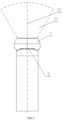
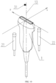
- the present disclosure provides a lesion locating method which, referring to FIGs. 1 to 15 , involves locating a lesion 32 in a body by locating a mark 31 on a body surface, and using an image acquisition assembly in locating to locate the mark 31, so that a center line 13 of the ultrasound probe 1 coincides with the mark 31.
- the ultrasound probe 1 is aligned with the mark 31, namely, aligned with the lesion 32.
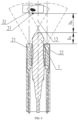
- the image acquisition assembly includes an ultrasound probe 1, and at least one camera 2 distributed on one side or both sides of a sector-scanning plane 11 of the ultrasound probe 1 and fixed in position relative to the ultrasound probe 1, and a center line 23 of the camera 2 is parallel to the center line 13 of the ultrasound probe 1.
- the lesion locating method includes the following steps S1 to S2.
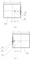
- a reference view 4 (including 41, 42) according to data acquired in real time by the camera 2 (including 21, 22), where the reference view 4 has a preset size, and a virtual mark point 41 corresponding to the mark 31 is formed in the reference view 4.
- a camera 2 is used to collect camera data and form a reference view 4 which assists the ultrasound probe 1 in rapid locating with a position of a mark 31 in the reference view 4, and after the reference view 4 is formed, the locating can be completed by controlling movement of the image acquisition assembly according to the reference view 4 without any manual operation, which not only reduces the difficulty of locating, but also increases the efficiency of lesion locating, and saves the operation time.
- forming the reference view 4 according to the data acquired in real time by the camera 2 (S1) includes the following steps S101 to S103.
- the ultrasound probe 1 is a B-mode ultrasound probe, and the current height distance can be obtained by processing ultrasonic data obtained by the B-mode ultrasound probe.
- the current height distance can be directly read, and when the current height is obtained in this manner, an acquisition range of the ultrasound probe needs to cover the mark point when the ultrasound probe is positioned at a pre-locating height.
- other devices may be used to obtain the current height distance, but this method of directly obtaining the current height distance with the ultrasound probe 1 is beneficial to simplifying the device and reducing the cost.
- calculating the actual locating trajectory (S2) further includes the following step S201.
- forming the reference view 4 (S1) includes the following step S102.
- a preset value of the pre-locating height may be set, and a pre-locating instruction is input so that the pre-locating height is equal to the preset value and the proportional relation is a fixed value.
- the ultrasound probe 1 is moved to a position with a fixed height difference from the mark 31, which may help to reduce the amount of computational data and implement faster locating.
- it is also possible to establish a calculation model of the imaging proportional relation by taking the preset value of the pre-locating height as a variable, and calculate an actual imaging proportional relation after obtaining a value of the pre-locating height.
- the imaging proportional relation may be calculated from an actual distance from the center line of the camera 2 to the side edge contour and a reference distance in the reference view 4.
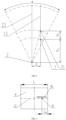
- calculating the actual longitudinal displacement which includes the following steps S2021a to S2021b.
- one camera 2 is provided, then the following step is included: at S2022, calculating the actual transverse displacement, which includes the following steps S2022a to S2022b.
- L 0 arctan h 1 + h 2 a ⁇ ⁇ ⁇ ⁇ 2 ⁇ ⁇ L
- L 0 is a virtual transverse displacement component
- a is a center distance between the ultrasound probe 1 and the camera 2
- h 1 is a height distance between the ultrasound probe 1 and the camera 2
- h 2 is the pre-locating height
- ⁇ is a viewing angle corresponding to an acquisition region of the camera 2 in the transverse direction
- L is a view width corresponding to the reference view 4 in the transverse direction.
- the sector-scanning plane 11 of the ultrasound probe 1 may have, but is not limited to, a sector shape.
- a reference scale 42 with fixed position and shape is set corresponding to the reference view.
- the reference scale 42 has corresponding scale values which are converted into and displayed as size values corresponding to the actual acquisition region of the camera according to an imaging proportion.
- the reference scale 42 is merged and formed into the reference view 4, and the reference scale 42 does not change position with any movement of the image in the display window, or change with the imaging proportion, so that the actual transverse displacement can be visually observed from the scale 42.
- the pre-locating height h 2 is preset to be a fixed value
- the displayed scale value is a fixed value
- the reference scale may be formed in the reference view, or provided on a display screen or any other device for displaying the reference view.
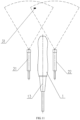
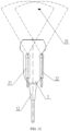
- two cameras 2 are provided, including a first camera 21 and a second camera 22.
- the first camera 21 and the second camera 22 are symmetrically distributed on two sides of the sector-scanning plane 11 of the ultrasound probe 1, and have a same height difference from the ultrasound probe 1.
- the first camera 21 acquires data and forms a first reference view 4a (see FIG. 8 )
- the second camera 22 acquires data and forms a second reference view 4b (see FIG. 9 )
- the step S2022 of calculating the actual transverse displacement includes: calculating the actual transverse displacement from a position of the virtual mark point 41 in the first reference view 4a and a position of the virtual mark point 41 in the second reference view 4b.
- y is an actual transverse displacement component
- a is a center distance between the ultrasound probe 1 and each camera 2
- L 1 is a transverse distance between the virtual mark point 41 in the first reference view 4a and a view center
- L 2 is a transverse distance between the virtual mark point 41 in the second reference view 4b and the view center
- images acquired by the first camera 21 and the second camera 22 each have a viewing angle ⁇ in the transverse direction
- the first reference view 4a and the second reference view 4b each have a preset view width L.
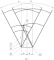
- two cameras 2 are provided, including a first camera 21 and a second camera 22, but the first camera 21 and the second camera 22 are distributed on two sides of the sector-scanning plane 11 of the ultrasound probe 1. At least one of the first camera or the second camera has a center line deviating from a midperpendicular plane of the sector-scanning plane of the ultrasound probe, and the first camera 21 and the second camera 22 have a same height difference from the ultrasound probe 1.
- the first camera 21 acquires data and forms a first reference view 4a
- the second camera 22 acquires data and forms a second reference view 4b, so: the step S202 of calculating the actual locating trajectory includes the following steps S2021 to S2022.
- the first camera 21 and the second camera 22 are disposed at flexible positions relative to the ultrasound probe 1, so as to avoid other devices in use, and be applicable in a wider range.
- a virtual projection point of the center line 13 of the ultrasound probe 1 is taken as an origin
- a virtual sector-scanning projection line of the sector-scanning plane 11 of the ultrasound probe is taken as a Y axis
- a virtual midperpendicular projection line of the midperpendicular plane 12 of the sector-scanning plane 11 of the ultrasound probe is taken as an X axis to establish a coordinate system
- cameras may be divided into at least two camera groups, each of which includes one or two cameras, an actual locating trajectory to be verified is formed according to a reference view acquired and formed by a camera group, and a final actual locating trajectory is obtained according to at least two actual locating trajectories to be verified.
- At least two cameras are provided, including a first camera and a second camera, where the first camera and the second camera are symmetrically distributed on two sides of the sector-scanning plane of the ultrasound probe, and each have a center line on a midperpendicular plane of the sector-scanning plane of the ultrasound probe and a same height difference from the ultrasound probe.
- a first actual locating trajectory is calculated from a corresponding first reference view or second reference view formed by the first camera or the second camera, that is, determined from a single camera; a second actual locating trajectory is calculated from corresponding reference views formed by the first camera and the second camera, that is, determined from two cameras, and then a final actual locating trajectory is determined from the first actual locating trajectory and the second actual locating trajectory.
- At least two cameras are provided, including a first camera and a second camera, where the first camera and the second camera are distributed on two sides of the sector-scanning plane of the ultrasound probe, a center line of the first camera is located on the midperpendicular plane of the sector-scanning plane of the ultrasound probe, while a center line of the second camera deviates from the midperpendicular plane of the sector-scanning plane of the ultrasound probe, the first camera and the second camera have a same height difference from the ultrasound probe, and while locating a lesion, a first actual locating trajectory is calculated from a corresponding reference view formed by the first camera, a second actual locating trajectory is calculated from corresponding reference views formed by the two cameras, and a final actual locating trajectory is determined from the first actual locating trajectory and the second actual locating trajectory.
- At least three cameras are provided, including a first camera, a second camera and a third camera, where the first camera and the third camera are distributed on one side of the sector-scanning plane of the ultrasound probe, the second camera is distributed on the other side of the sector-scanning plane of the ultrasound probe, a center line of the third camera is located on the midperpendicular plane of the sector-scanning plane of the ultrasound probe, while center lines of the first camera and the second camera deviate from the midperpendicular plane of the sector-scanning plane of the ultrasound probe, the first camera, the second camera and the third camera have a same height difference from the ultrasound probe, and while locating a lesion, a first actual locating trajectory is calculated from a corresponding reference view formed by the third camera, a second actual locating trajectory is calculated from corresponding first reference view and second reference view formed by the first camera and the second camera, and a final actual locating trajectory is determined from the first actual locating trajectory and the second actual locating trajectory.
- At least four cameras are provided, including a first camera, a second camera, a third camera and a fourth camera, where the first camera and the second camera are symmetrically distributed on two sides of the sector-scanning plane of the ultrasound probe, and each have a center line on the midperpendicular plane of the sector-scanning plane of the ultrasound probe, while the third camera and the fourth camera are distributed on two sides of the sector-scanning plane of the ultrasound probe, and each have a center line deviating from the midperpendicular plane of the sector-scanning plane of the ultrasound probe, a first actual locating trajectory is calculated from corresponding reference views formed by the first camera and the second camera, a second actual locating trajectory is calculated from corresponding reference views formed by the third camera and the fourth camera, and a final actual locating trajectory is determined from the first actual locating trajectory and the second actual locating trajectory.
- At least four cameras are provided, including a first camera, a second camera, a third camera and a fourth camera, where the first camera and the second camera are symmetrically distributed on two sides of the sector-scanning plane of the ultrasound probe, and each have a center line on the midperpendicular plane of the sector-scanning plane of the ultrasound probe, while the third camera and the fourth camera are distributed on two sides of the sector-scanning plane of the ultrasound probe, and each have a center line deviating from the midperpendicular plane of the sector-scanning plane of the ultrasound probe, a first actual locating trajectory is calculated from corresponding reference views formed by the first camera and the second camera, a second actual locating trajectory is calculated from corresponding reference views formed by the third camera and the fourth camera, a third actual locating trajectory is calculated from a corresponding reference view formed by the first camera or the second camera, and a final actual locating trajectory is determined from the first actual locating trajectory, the second actual locating trajectory, and the third actual locating trajectory.
- the final actual locating trajectory is determined according to locating trajectories to be verified (the first actual locating trajectory, the second actual locating trajectory or the third actual locating trajectory)
- a difference value of any locating trajectory to be verified is greater than a preset threshold
- an abnormal warning signal may be given; and if the difference value of each locating trajectory to be verified is smaller than or equal to the preset threshold, the locating trajectories to be verified are averaged to obtain an average value which is taken as the final actual locating trajectory.
- the actual locating trajectory is determined through calculation, and then the movement of the ultrasound probe 1, and thus of the whole image acquisition assembly, is controlled according to the calculated actual locating trajectory.
- the actual locating trajectory may not be calculated, and instead, the center line 13 of the ultrasound probe 1 is merged into the reference view 4 as a virtual projection point according to an actual positional relationship between the camera 2 and the ultrasound probe 1, then according to a positional relationship of the virtual mark point 41 and the virtual projection point in the reference view 4, a movement direction corresponding to coincidence of the virtual projection point and the virtual mark point 41 is determined, and the ultrasound probe 1 (that is, the whole image acquisition assembly) is controlled to move according to the movement direction, until the virtual projection point and the virtual mark point 41 coincide with each other in the reference view 4.
- the center line 23 of the camera 2 corresponds to a center position of the reference view on the reference view 4
- the center line 13 of the ultrasound probe 1 has an orientation corresponding to the center line of the camera 2
- the virtual projection point has a direction corresponding to the virtual mark point 41
- orientations of the center line 13 of the ultrasound probe 1 and the center line of the camera 2 and a distance between the virtual projection point and the virtual mark point 41 are determined according to the imaging proportion.
- the present disclosure further provides a lesion locating system which locates a lesion by locating a mark 31 on a body surface.
- the detailed method for locating a lesion with the lesion locating system and the effect obtained thereby may refer to related description of the lesion locating method.
- the lesion locating system of the present disclosure includes:
- the processor may be a general purpose processor, including a central processing unit (CPU), a network processor (NP), or the like; or may be a digital signal processor (DSP), an application specific integrated circuit (ASIC), a field-programmable gate array (FPGA) or any other programmable logic device, a discrete gate or a transistor logic device, or a discrete hardware component.
- CPU central processing unit
- NP network processor
- DSP digital signal processor
- ASIC application specific integrated circuit
- FPGA field-programmable gate array
- the lesion locating system further includes:
- the processor includes a pre-locating processing unit configured to control the actuating mechanism to move according to the pre-locating instruction, judge, after an action corresponding to the pre-locating instruction is completed by the actuating mechanism, whether a current view acquired and formed by the camera 2 contains a virtual mark point 41 corresponding to the mark 31, and take, if the current view contains the virtual mark point 41 corresponding to the mark 31, the current view as the reference view 4.
- a pre-locating processing unit configured to control the actuating mechanism to move according to the pre-locating instruction, judge, after an action corresponding to the pre-locating instruction is completed by the actuating mechanism, whether a current view acquired and formed by the camera 2 contains a virtual mark point 41 corresponding to the mark 31, and take, if the current view contains the virtual mark point 41 corresponding to the mark 31, the current view as the reference view 4.
- the actual locating trajectory calculation unit has a motion boundary condition calculation subunit for calculating a motion boundary condition
- the motion boundary condition calculation subunit is configured to limit, according to the pre-locating height, a motion boundary condition of the image acquisition assembly so that the ultrasound probe 1 is movable within a preset plane.
- the preset plane is a plane perpendicular to the center line 13 of the ultrasound probe 1 and corresponding to the pre-locating height.
- the processor further includes an imaging unit configured to: establish an imaging proportional relation between the current view and an actual acquisition region of the camera 2, and form the reference view 4 according to the imaging proportional relation.
- a preset value of the pre-locating height may be set, and a pre-locating instruction is input so that the pre-locating height is equal to the preset value and the proportional relation is a fixed value.
- the ultrasound probe 1 is moved to a position with a fixed height difference from the mark 31, which may help to reduce the amount of computational data and implement faster locating.
- it is also possible to establish a calculation model of the imaging proportional relation by taking the preset value of the pre-locating height as a variable, and calculate an actual imaging proportional relation after obtaining a value of the pre-locating height.
- the imaging proportional relation is calculated from an actual distance from the center line of the camera 2 to the side edge contour and a reference distance in the reference view 4.
- the center line 23 of the camera 2 is located on a midperpendicular plane 12 of the sector-scanning plane 11 of the ultrasound probe, so
- L 0 is a virtual transverse displacement component
- a is a center distance between the ultrasound probe 1 and the camera 2
- h 1 is a height distance between the ultrasound probe 1 and the camera 2
- h 2 is the pre-locating height
- ⁇ is a viewing angle corresponding to an acquisition region of the camera 2 in the transverse direction
- L is a view width corresponding to the reference view 4 in the transverse direction.
- a reference scale with fixed position and shape is provided in the reference view 4, and the reference scale 42 has corresponding scale values which are converted into and displayed as size values corresponding to the actual acquisition region of the camera according to an imaging proportion.
- the reference scale may be provided on the reference view display device.
- two cameras 2 are provided, including a first camera 21 and a second camera 22.
- the first camera 21 and the second camera 22 are symmetrically distributed on two sides of the sector-scanning plane 11 of the ultrasound probe 1, and have a same height difference from the ultrasound probe 1.
- y is an actual transverse displacement component
- a is a center distance between the ultrasound probe 1 and each camera 2
- L 1 is a transverse distance between the virtual mark point 41 in the first reference view 4a and a view center
- L 2 is a transverse distance between the virtual mark point 41 in the second reference view 4b and the view center
- images acquired by the first camera 21 and the second camera 22 each have a
- two cameras 2 are provided, including a first camera 21 and a second camera 22.
- the first camera 21 and the second camera 22 are distributed on two sides of the sector-scanning plane 11 of the ultrasound probe 1, at least one of the first camera or the second camera has a center line deviating from a midperpendicular plane of the sector-scanning plane of the ultrasound probe, and the first camera 21 and the second camera 22 have a same height difference from the ultrasound probe 1.
- the first camera 21 and the second camera 22 are disposed at flexible positions relative to the ultrasound probe 1, so as to avoid other devices in use, and be applicable in a wider range.
- the imaging unit is configured to: form a first reference view 4a from data acquired by the first camera 21, and form a second reference view 4b from data acquired by the second camera 22; and the actual locating trajectory calculation unit is configured to: calculate a virtual transverse displacement and a virtual longitudinal displacement according to positions of the virtual mark point 41 in the first reference view 4a and the second reference view 4b; and calculate an actual transverse displacement and an actual longitudinal displacement according to the virtual transverse displacement, the virtual longitudinal displacement and the imaging proportional relation.
- a virtual projection point of the center line of the ultrasound probe 1 is taken as an origin
- a virtual sector-scanning projection line of the sector-scanning plane 11 of the ultrasound probe is taken as a Y axis
- a virtual midperpendicular projection line of the midperpendicular plane 12 of the sector-scanning plane 11 of the ultrasound probe is taken as an X axis to establish a coordinate system
- the lesion locating system is provided with multiple camera groups, each of which includes one or two cameras, each actual locating trajectory calculation unit obtains an actual locating trajectory to be verified according to one camera group, and the processor further includes a verification unit configured to obtain a final actual locating trajectory according to at least two actual locating trajectories to be verified.
- the processor is further configured to:
Landscapes
- Health & Medical Sciences (AREA)
- Life Sciences & Earth Sciences (AREA)
- Engineering & Computer Science (AREA)
- Biomedical Technology (AREA)
- Nuclear Medicine, Radiotherapy & Molecular Imaging (AREA)
- Radiology & Medical Imaging (AREA)
- Animal Behavior & Ethology (AREA)
- General Health & Medical Sciences (AREA)
- Public Health (AREA)
- Veterinary Medicine (AREA)
- Physics & Mathematics (AREA)
- Biophysics (AREA)
- Pathology (AREA)
- Heart & Thoracic Surgery (AREA)
- Medical Informatics (AREA)
- Molecular Biology (AREA)
- Surgery (AREA)
- Vascular Medicine (AREA)
- Computer Vision & Pattern Recognition (AREA)
- Ultra Sonic Daignosis Equipment (AREA)
- Radiation-Therapy Devices (AREA)
Applications Claiming Priority (2)
| Application Number | Priority Date | Filing Date | Title |
|---|---|---|---|
| CN202011551545.3A CN112704514B (zh) | 2020-12-24 | 2020-12-24 | 病灶定位方法及病灶定位系统 |
| PCT/CN2021/115360 WO2022134647A1 (zh) | 2020-12-24 | 2021-08-30 | 病灶定位方法及病灶定位系统 |
Publications (3)
| Publication Number | Publication Date |
|---|---|
| EP4268727A1 true EP4268727A1 (de) | 2023-11-01 |
| EP4268727A4 EP4268727A4 (de) | 2024-11-13 |
| EP4268727B1 EP4268727B1 (de) | 2026-02-11 |
Family
ID=75544338
Family Applications (1)
| Application Number | Title | Priority Date | Filing Date |
|---|---|---|---|
| EP21908650.1A Active EP4268727B1 (de) | 2020-12-24 | 2021-08-30 | Läsionpositionierungsverfahren und läsionpositionierungssystem |
Country Status (7)
| Country | Link |
|---|---|
| EP (1) | EP4268727B1 (de) |
| JP (1) | JP7563803B2 (de) |
| KR (1) | KR102908648B1 (de) |
| CN (1) | CN112704514B (de) |
| AU (1) | AU2021406651B2 (de) |
| CA (1) | CA3198932A1 (de) |
| WO (1) | WO2022134647A1 (de) |
Families Citing this family (5)
| Publication number | Priority date | Publication date | Assignee | Title |
|---|---|---|---|---|
| JP2023530477A (ja) | 2020-06-18 | 2023-07-18 | ヒストソニックス,インコーポレーテッド | 組織破砕音響/患者結合システムおよび方法 |
| CN112704514B (zh) * | 2020-12-24 | 2021-11-02 | 重庆海扶医疗科技股份有限公司 | 病灶定位方法及病灶定位系统 |
| EP4351718A4 (de) | 2021-06-07 | 2025-03-26 | The Regents of The University of Michigan | Minimal invasive histotripsiesysteme und verfahren |
| KR102767437B1 (ko) * | 2022-07-25 | 2025-02-14 | 중앙대학교 산학협력단 | 영상 융합을 위한 3차원 초음파 탐촉자 및 영상 융합 방법 |
| CN115808141A (zh) * | 2022-11-21 | 2023-03-17 | 中广核检测技术有限公司 | 一种视觉引导的超声探头架及定位方法 |
Family Cites Families (26)
| Publication number | Priority date | Publication date | Assignee | Title |
|---|---|---|---|---|
| FR2760277B1 (fr) * | 1997-02-28 | 1999-03-26 | Commissariat Energie Atomique | Procede et dispositif de localisation d'un objet dans l'espace |
| US6500119B1 (en) * | 1999-12-01 | 2002-12-31 | Medical Tactile, Inc. | Obtaining images of structures in bodily tissue |
| CA2314794A1 (en) * | 2000-08-01 | 2002-02-01 | Dimitre Hristov | Apparatus for lesion or organ localization |
| JP2007508913A (ja) * | 2003-10-21 | 2007-04-12 | ザ ボード オブ トラスティーズ オブ ザ リーランド スタンフォード ジュニア ユニヴァーシティ | 術中ターゲティングのシステムおよび方法 |
| JP4772540B2 (ja) * | 2006-03-10 | 2011-09-14 | 株式会社東芝 | 超音波診断装置 |
| CN101569541B (zh) * | 2008-04-29 | 2011-04-06 | 香港理工大学 | 三维超声波成像系统 |
| JP5486182B2 (ja) * | 2008-12-05 | 2014-05-07 | キヤノン株式会社 | 情報処理装置および情報処理方法 |
| US9113817B2 (en) * | 2010-10-20 | 2015-08-25 | Siemens Medical Solutions Usa, Inc. | System for locating anatomical objects in ultrasound imaging |
| WO2014113530A1 (en) * | 2013-01-17 | 2014-07-24 | Tractus Corporation | Method, apparatus and system for complete examination of tissue with hand-held imaging devices having mounted cameras |
| US11027149B2 (en) * | 2012-01-12 | 2021-06-08 | Sensus Healthcare, Inc. | Hybrid ultrasound-guided superficial radiotherapy system and method |
| CN202982047U (zh) * | 2012-06-11 | 2013-06-12 | 大连理工大学 | 超声波探头的光学标定装置 |
| EP3247281B1 (de) * | 2015-01-23 | 2020-12-02 | The University of North Carolina at Chapel Hill | Vorrichtungen, systeme und verfahren zur vorklinischen ultraschallabbildung von patienten |
| WO2016134093A1 (en) * | 2015-02-19 | 2016-08-25 | Metritrack, Inc. | System and method for positional registration of medical image data |
| CN104644205A (zh) * | 2015-03-02 | 2015-05-27 | 上海联影医疗科技有限公司 | 用于影像诊断的患者定位方法及系统 |
| CN105030275A (zh) * | 2015-08-31 | 2015-11-11 | 姜殿威 | 超声探查辅助定位系统 |
| CN106952347B (zh) * | 2017-03-28 | 2019-12-17 | 华中科技大学 | 一种基于双目视觉的超声手术辅助导航系统 |
| CN109223030B (zh) * | 2017-07-11 | 2022-02-18 | 中慧医学成像有限公司 | 一种掌上式三维超声成像系统和方法 |
| CN107865671B (zh) * | 2017-12-12 | 2023-05-26 | 成都优途科技有限公司 | 基于单目视觉定位的三维超声扫描系统及控制方法 |
| US20190209119A1 (en) * | 2018-01-08 | 2019-07-11 | Rivanna Medical Llc | System and Method for Angular Alignment of a Probe at a Target Location |
| EP3530191A1 (de) | 2018-02-27 | 2019-08-28 | Leica Instruments (Singapore) Pte. Ltd. | Ultraschallkopf mit kombination von ultraschall und optik |
| CN108403146B (zh) * | 2018-03-20 | 2020-06-30 | 余夏夏 | 基于多传感器信息融合的三维超声成像方法及装置 |
| US11235178B2 (en) * | 2018-09-04 | 2022-02-01 | General Electric Company | Neuromodulation energy application techniques |
| CN109171817B (zh) * | 2018-09-05 | 2021-12-07 | 浙江深博医疗技术有限公司 | 三维乳腺超声扫描方法及超声扫描系统 |
| US11810473B2 (en) * | 2019-01-29 | 2023-11-07 | The Regents Of The University Of California | Optical surface tracking for medical simulation |
| CN112568935B (zh) | 2019-09-29 | 2024-06-25 | 中慧医学成像有限公司 | 基于三维追踪相机的三维超声成像方法和系统 |
| CN112704514B (zh) * | 2020-12-24 | 2021-11-02 | 重庆海扶医疗科技股份有限公司 | 病灶定位方法及病灶定位系统 |
-
2020
- 2020-12-24 CN CN202011551545.3A patent/CN112704514B/zh active Active
-
2021
- 2021-08-30 JP JP2023524412A patent/JP7563803B2/ja active Active
- 2021-08-30 EP EP21908650.1A patent/EP4268727B1/de active Active
- 2021-08-30 WO PCT/CN2021/115360 patent/WO2022134647A1/zh not_active Ceased
- 2021-08-30 CA CA3198932A patent/CA3198932A1/en active Pending
- 2021-08-30 KR KR1020237015344A patent/KR102908648B1/ko active Active
- 2021-08-30 AU AU2021406651A patent/AU2021406651B2/en active Active
Also Published As
| Publication number | Publication date |
|---|---|
| KR102908648B1 (ko) | 2026-01-07 |
| JP7563803B2 (ja) | 2024-10-08 |
| US20230371920A1 (en) | 2023-11-23 |
| EP4268727B1 (de) | 2026-02-11 |
| AU2021406651A1 (en) | 2023-06-01 |
| CA3198932A1 (en) | 2022-06-30 |
| CN112704514A (zh) | 2021-04-27 |
| KR20230082664A (ko) | 2023-06-08 |
| EP4268727A4 (de) | 2024-11-13 |
| CN112704514B (zh) | 2021-11-02 |
| JP2023546456A (ja) | 2023-11-02 |
| WO2022134647A1 (zh) | 2022-06-30 |
| AU2021406651B2 (en) | 2025-04-24 |
Similar Documents
| Publication | Publication Date | Title |
|---|---|---|
| EP4268727A1 (de) | Läsionpositionierungsverfahren und läsionpositionierungssystem | |
| US8585600B2 (en) | Ultrasound volume probe navigation and control method and device | |
| CN112122840A (zh) | 一种基于机器人焊接的视觉定位焊接系统及焊接方法 | |
| CN103690191B (zh) | 一种超声探头智能连续扫描装置及其扫描方法 | |
| WO2023273093A1 (zh) | 一种人体三维模型获取方法、装置、智能终端及存储介质 | |
| WO2021078065A1 (zh) | 乳房三维点云重建方法、装置、存储介质及计算机设备 | |
| CN106373089B (zh) | B型与弹性双模态超声跟腱图像拼接方法 | |
| CN101543412B (zh) | 基于二维超声成像装置的图形坐标分量计算方法及装置 | |
| CN105082161A (zh) | 双目立体摄像机机器人视觉伺服控制装置及其使用方法 | |
| CN104184932A (zh) | 球机控制方法及装置 | |
| CN106361372A (zh) | 一种超声探头智能扫描路径规划方法 | |
| Chatelain et al. | Confidence-driven control of an ultrasound probe: Target-specific acoustic window optimization | |
| CN102081697B (zh) | 一种在超声成像空间中定义感兴趣容积的方法及其装置 | |
| US12616439B2 (en) | Lesion locating method and lesion locating system | |
| CN119228786A (zh) | 钢筋绑扎点全景识别方法、系统及电子设备 | |
| CN110084855A (zh) | 一种改进cbct几何参数标定算法 | |
| CN117257457A (zh) | 一种基于实时超声图像配准融合的手术导航方法 | |
| CN107693047A (zh) | 超声成像中基于对称组织的体标设置方法及系统 | |
| RU2816628C1 (ru) | Способ локализации поражения и система локализации поражения | |
| CN118453133B (zh) | 一种机器人夹持的腹腔镜位姿控制方法及相关装置 | |
| CN214971278U (zh) | 病灶定位探头、病灶定位系统及聚焦超声治疗设备 | |
| CN115381484B (zh) | 一种双平面超声换能器探头及其换能器位置的设置方法 | |
| CN100496404C (zh) | 实现扩景三维超声波图像的方法和超声波装置 | |
| KR102598211B1 (ko) | 방광내 요량 측정용 초음파 스캐너 | |
| CN109793999A (zh) | Hifu治疗系统的静态三维轮廓体图像的构建方法 |
Legal Events
| Date | Code | Title | Description |
|---|---|---|---|
| STAA | Information on the status of an ep patent application or granted ep patent |
Free format text: STATUS: THE INTERNATIONAL PUBLICATION HAS BEEN MADE |
|
| PUAI | Public reference made under article 153(3) epc to a published international application that has entered the european phase |
Free format text: ORIGINAL CODE: 0009012 |
|
| STAA | Information on the status of an ep patent application or granted ep patent |
Free format text: STATUS: REQUEST FOR EXAMINATION WAS MADE |
|
| 17P | Request for examination filed |
Effective date: 20230330 |
|
| AK | Designated contracting states |
Kind code of ref document: A1 Designated state(s): AL AT BE BG CH CY CZ DE DK EE ES FI FR GB GR HR HU IE IS IT LI LT LU LV MC MK MT NL NO PL PT RO RS SE SI SK SM TR |
|
| DAV | Request for validation of the european patent (deleted) | ||
| DAX | Request for extension of the european patent (deleted) | ||
| A4 | Supplementary search report drawn up and despatched |
Effective date: 20241015 |
|
| RIC1 | Information provided on ipc code assigned before grant |
Ipc: A61B 90/00 20160101ALI20241009BHEP Ipc: A61B 34/20 20160101ALI20241009BHEP Ipc: A61N 7/00 20060101ALI20241009BHEP Ipc: A61B 8/00 20060101AFI20241009BHEP |
|
| GRAP | Despatch of communication of intention to grant a patent |
Free format text: ORIGINAL CODE: EPIDOSNIGR1 |
|
| STAA | Information on the status of an ep patent application or granted ep patent |
Free format text: STATUS: GRANT OF PATENT IS INTENDED |
|
| INTG | Intention to grant announced |
Effective date: 20251117 |
|
| GRAS | Grant fee paid |
Free format text: ORIGINAL CODE: EPIDOSNIGR3 |
|
| GRAA | (expected) grant |
Free format text: ORIGINAL CODE: 0009210 |
|
| STAA | Information on the status of an ep patent application or granted ep patent |
Free format text: STATUS: THE PATENT HAS BEEN GRANTED |
|
| P01 | Opt-out of the competence of the unified patent court (upc) registered |
Free format text: CASE NUMBER: UPC_APP_0018060_4268727/2025 Effective date: 20251217 |
|
| AK | Designated contracting states |
Kind code of ref document: B1 Designated state(s): AL AT BE BG CH CY CZ DE DK EE ES FI FR GB GR HR HU IE IS IT LI LT LU LV MC MK MT NL NO PL PT RO RS SE SI SK SM TR |
|
| REG | Reference to a national code |
Ref country code: CH Ref legal event code: F10 Free format text: ST27 STATUS EVENT CODE: U-0-0-F10-F00 (AS PROVIDED BY THE NATIONAL OFFICE) Effective date: 20260211 Ref country code: GB Ref legal event code: FG4D |
|
| REG | Reference to a national code |
Ref country code: DE Ref legal event code: R096 Ref document number: 602021047955 Country of ref document: DE |
|
| REG | Reference to a national code |
Ref country code: IE Ref legal event code: FG4D |