EP4268752A1 - Cathéter à panier avec structure en trèfle pour empêcher le flambage et la rétention pour électrodes - Google Patents
Cathéter à panier avec structure en trèfle pour empêcher le flambage et la rétention pour électrodes Download PDFInfo
- Publication number
- EP4268752A1 EP4268752A1 EP23170409.9A EP23170409A EP4268752A1 EP 4268752 A1 EP4268752 A1 EP 4268752A1 EP 23170409 A EP23170409 A EP 23170409A EP 4268752 A1 EP4268752 A1 EP 4268752A1
- Authority
- EP
- European Patent Office
- Prior art keywords
- spine
- spines
- medical probe
- electrodes
- longitudinal axis
- Prior art date
- Legal status (The legal status is an assumption and is not a legal conclusion. Google has not performed a legal analysis and makes no representation as to the accuracy of the status listed.)
- Pending
Links
- 239000000523 sample Substances 0.000 abstract description 56
- 230000008878 coupling Effects 0.000 abstract 1
- 238000010168 coupling process Methods 0.000 abstract 1
- 238000005859 coupling reaction Methods 0.000 abstract 1
- 230000014759 maintenance of location Effects 0.000 description 45
- 238000002679 ablation Methods 0.000 description 44
- 238000000034 method Methods 0.000 description 37
- 210000001519 tissue Anatomy 0.000 description 29
- 238000004520 electroporation Methods 0.000 description 20
- 230000002051 biphasic effect Effects 0.000 description 14
- 230000002427 irreversible effect Effects 0.000 description 13
- 230000002262 irrigation Effects 0.000 description 13
- 238000003973 irrigation Methods 0.000 description 13
- 210000004027 cell Anatomy 0.000 description 12
- 210000005003 heart tissue Anatomy 0.000 description 12
- 238000003780 insertion Methods 0.000 description 12
- 230000037431 insertion Effects 0.000 description 12
- 239000012530 fluid Substances 0.000 description 9
- 239000000463 material Substances 0.000 description 9
- 238000007674 radiofrequency ablation Methods 0.000 description 9
- 241001465754 Metazoa Species 0.000 description 8
- KDLHZDBZIXYQEI-UHFFFAOYSA-N Palladium Chemical compound [Pd] KDLHZDBZIXYQEI-UHFFFAOYSA-N 0.000 description 8
- 230000005684 electric field Effects 0.000 description 8
- 238000005516 engineering process Methods 0.000 description 8
- BASFCYQUMIYNBI-UHFFFAOYSA-N platinum Chemical compound [Pt] BASFCYQUMIYNBI-UHFFFAOYSA-N 0.000 description 8
- 230000002441 reversible effect Effects 0.000 description 8
- 239000000853 adhesive Substances 0.000 description 6
- 230000001070 adhesive effect Effects 0.000 description 6
- 239000007933 dermal patch Substances 0.000 description 6
- 239000010935 stainless steel Substances 0.000 description 6
- 229910001220 stainless steel Inorganic materials 0.000 description 6
- 230000001225 therapeutic effect Effects 0.000 description 6
- 229910000684 Cobalt-chrome Inorganic materials 0.000 description 5
- WAIPAZQMEIHHTJ-UHFFFAOYSA-N [Cr].[Co] Chemical compound [Cr].[Co] WAIPAZQMEIHHTJ-UHFFFAOYSA-N 0.000 description 5
- 229910045601 alloy Inorganic materials 0.000 description 5
- 239000000956 alloy Substances 0.000 description 5
- 238000013459 approach Methods 0.000 description 5
- 206010003119 arrhythmia Diseases 0.000 description 5
- 239000010952 cobalt-chrome Substances 0.000 description 5
- 230000006870 function Effects 0.000 description 5
- 229910001000 nickel titanium Inorganic materials 0.000 description 5
- 206010003658 Atrial Fibrillation Diseases 0.000 description 4
- PCHJSUWPFVWCPO-UHFFFAOYSA-N gold Chemical compound [Au] PCHJSUWPFVWCPO-UHFFFAOYSA-N 0.000 description 4
- 229910052737 gold Inorganic materials 0.000 description 4
- 239000010931 gold Substances 0.000 description 4
- 230000001965 increasing effect Effects 0.000 description 4
- 230000016507 interphase Effects 0.000 description 4
- HLXZNVUGXRDIFK-UHFFFAOYSA-N nickel titanium Chemical compound [Ti].[Ti].[Ti].[Ti].[Ti].[Ti].[Ti].[Ti].[Ti].[Ti].[Ti].[Ni].[Ni].[Ni].[Ni].[Ni].[Ni].[Ni].[Ni].[Ni].[Ni].[Ni].[Ni].[Ni].[Ni] HLXZNVUGXRDIFK-UHFFFAOYSA-N 0.000 description 4
- 229910052763 palladium Inorganic materials 0.000 description 4
- 229910052697 platinum Inorganic materials 0.000 description 4
- RTAQQCXQSZGOHL-UHFFFAOYSA-N Titanium Chemical compound [Ti] RTAQQCXQSZGOHL-UHFFFAOYSA-N 0.000 description 3
- 230000006793 arrhythmia Effects 0.000 description 3
- 230000000747 cardiac effect Effects 0.000 description 3
- 230000000694 effects Effects 0.000 description 3
- 238000005421 electrostatic potential Methods 0.000 description 3
- 230000004907 flux Effects 0.000 description 3
- 238000004519 manufacturing process Methods 0.000 description 3
- 229910052719 titanium Inorganic materials 0.000 description 3
- 239000010936 titanium Substances 0.000 description 3
- 210000005166 vasculature Anatomy 0.000 description 3
- 208000006687 Esophageal Fistula Diseases 0.000 description 2
- 206010065835 Oesophageal fistula Diseases 0.000 description 2
- 206010033799 Paralysis Diseases 0.000 description 2
- 206010049171 Pulmonary vein stenosis Diseases 0.000 description 2
- 238000005452 bending Methods 0.000 description 2
- 238000013461 design Methods 0.000 description 2
- 239000011521 glass Substances 0.000 description 2
- 238000002955 isolation Methods 0.000 description 2
- 238000013507 mapping Methods 0.000 description 2
- 230000002107 myocardial effect Effects 0.000 description 2
- 210000004165 myocardium Anatomy 0.000 description 2
- 210000000056 organ Anatomy 0.000 description 2
- 208000021090 palsy Diseases 0.000 description 2
- 210000003105 phrenic nerve Anatomy 0.000 description 2
- 239000011148 porous material Substances 0.000 description 2
- 230000009467 reduction Effects 0.000 description 2
- 238000012546 transfer Methods 0.000 description 2
- 206010003130 Arrhythmia supraventricular Diseases 0.000 description 1
- 206010003662 Atrial flutter Diseases 0.000 description 1
- 241000282693 Cercopithecidae Species 0.000 description 1
- VYZAMTAEIAYCRO-UHFFFAOYSA-N Chromium Chemical compound [Cr] VYZAMTAEIAYCRO-UHFFFAOYSA-N 0.000 description 1
- 241000124008 Mammalia Species 0.000 description 1
- FAPWRFPIFSIZLT-UHFFFAOYSA-M Sodium chloride Chemical compound [Na+].[Cl-] FAPWRFPIFSIZLT-UHFFFAOYSA-M 0.000 description 1
- 208000003734 Supraventricular Tachycardia Diseases 0.000 description 1
- 241000219793 Trifolium Species 0.000 description 1
- 208000027418 Wounds and injury Diseases 0.000 description 1
- HZEWFHLRYVTOIW-UHFFFAOYSA-N [Ti].[Ni] Chemical compound [Ti].[Ni] HZEWFHLRYVTOIW-UHFFFAOYSA-N 0.000 description 1
- 230000002159 abnormal effect Effects 0.000 description 1
- 230000004913 activation Effects 0.000 description 1
- 230000006978 adaptation Effects 0.000 description 1
- 238000010171 animal model Methods 0.000 description 1
- 238000003782 apoptosis assay Methods 0.000 description 1
- 230000006907 apoptotic process Effects 0.000 description 1
- 230000008901 benefit Effects 0.000 description 1
- 239000008280 blood Substances 0.000 description 1
- 210000004369 blood Anatomy 0.000 description 1
- 230000023555 blood coagulation Effects 0.000 description 1
- 238000009529 body temperature measurement Methods 0.000 description 1
- 210000000988 bone and bone Anatomy 0.000 description 1
- 239000003990 capacitor Substances 0.000 description 1
- 230000015556 catabolic process Effects 0.000 description 1
- 230000005779 cell damage Effects 0.000 description 1
- 230000030833 cell death Effects 0.000 description 1
- 208000037887 cell injury Diseases 0.000 description 1
- 210000000170 cell membrane Anatomy 0.000 description 1
- 210000003850 cellular structure Anatomy 0.000 description 1
- 238000006243 chemical reaction Methods 0.000 description 1
- 229910052804 chromium Inorganic materials 0.000 description 1
- 239000011651 chromium Substances 0.000 description 1
- 229910017052 cobalt Inorganic materials 0.000 description 1
- 239000010941 cobalt Substances 0.000 description 1
- GUTLYIVDDKVIGB-UHFFFAOYSA-N cobalt atom Chemical compound [Co] GUTLYIVDDKVIGB-UHFFFAOYSA-N 0.000 description 1
- 238000004891 communication Methods 0.000 description 1
- 150000001875 compounds Chemical class 0.000 description 1
- 239000004020 conductor Substances 0.000 description 1
- 230000006378 damage Effects 0.000 description 1
- 238000006731 degradation reaction Methods 0.000 description 1
- 238000002405 diagnostic procedure Methods 0.000 description 1
- 238000009826 distribution Methods 0.000 description 1
- 239000003814 drug Substances 0.000 description 1
- 229940079593 drug Drugs 0.000 description 1
- 239000012636 effector Substances 0.000 description 1
- 238000002001 electrophysiology Methods 0.000 description 1
- 230000007831 electrophysiology Effects 0.000 description 1
- 238000002594 fluoroscopy Methods 0.000 description 1
- 210000002064 heart cell Anatomy 0.000 description 1
- 238000010438 heat treatment Methods 0.000 description 1
- 230000013632 homeostatic process Effects 0.000 description 1
- 230000001939 inductive effect Effects 0.000 description 1
- 208000014674 injury Diseases 0.000 description 1
- 229910052741 iridium Inorganic materials 0.000 description 1
- GKOZUEZYRPOHIO-UHFFFAOYSA-N iridium atom Chemical compound [Ir] GKOZUEZYRPOHIO-UHFFFAOYSA-N 0.000 description 1
- 230000000670 limiting effect Effects 0.000 description 1
- 244000144972 livestock Species 0.000 description 1
- 238000002844 melting Methods 0.000 description 1
- 230000008018 melting Effects 0.000 description 1
- 229910052751 metal Inorganic materials 0.000 description 1
- 239000002184 metal Substances 0.000 description 1
- 150000002739 metals Chemical class 0.000 description 1
- 238000012986 modification Methods 0.000 description 1
- 230000004048 modification Effects 0.000 description 1
- 230000037361 pathway Effects 0.000 description 1
- 230000008823 permeabilization Effects 0.000 description 1
- 230000001766 physiological effect Effects 0.000 description 1
- 230000008569 process Effects 0.000 description 1
- 230000005522 programmed cell death Effects 0.000 description 1
- 230000001681 protective effect Effects 0.000 description 1
- 210000003492 pulmonary vein Anatomy 0.000 description 1
- 230000008439 repair process Effects 0.000 description 1
- 239000012858 resilient material Substances 0.000 description 1
- 230000000284 resting effect Effects 0.000 description 1
- 230000000717 retained effect Effects 0.000 description 1
- 230000033764 rhythmic process Effects 0.000 description 1
- 231100000241 scar Toxicity 0.000 description 1
- 229910001285 shape-memory alloy Inorganic materials 0.000 description 1
- 229910000679 solder Inorganic materials 0.000 description 1
- 238000005476 soldering Methods 0.000 description 1
- 239000007787 solid Substances 0.000 description 1
- 230000003685 thermal hair damage Effects 0.000 description 1
- 230000000451 tissue damage Effects 0.000 description 1
- 231100000827 tissue damage Toxicity 0.000 description 1
- 230000007704 transition Effects 0.000 description 1
- 238000002604 ultrasonography Methods 0.000 description 1
- 230000002792 vascular Effects 0.000 description 1
- 206010047302 ventricular tachycardia Diseases 0.000 description 1
- 238000003466 welding Methods 0.000 description 1
Images





Classifications
-
- A—HUMAN NECESSITIES
- A61—MEDICAL OR VETERINARY SCIENCE; HYGIENE
- A61B—DIAGNOSIS; SURGERY; IDENTIFICATION
- A61B18/00—Surgical instruments, devices or methods for transferring non-mechanical forms of energy to or from the body
- A61B18/04—Surgical instruments, devices or methods for transferring non-mechanical forms of energy to or from the body by heating
- A61B18/12—Surgical instruments, devices or methods for transferring non-mechanical forms of energy to or from the body by heating by passing a current through the tissue to be heated, e.g. high-frequency current
- A61B18/14—Probes or electrodes therefor
- A61B18/1492—Probes or electrodes therefor having a flexible, catheter-like structure, e.g. for heart ablation
-
- A—HUMAN NECESSITIES
- A61—MEDICAL OR VETERINARY SCIENCE; HYGIENE
- A61B—DIAGNOSIS; SURGERY; IDENTIFICATION
- A61B18/00—Surgical instruments, devices or methods for transferring non-mechanical forms of energy to or from the body
- A61B2018/00053—Mechanical features of the instrument of device
- A61B2018/0016—Energy applicators arranged in a two- or three dimensional array
-
- A—HUMAN NECESSITIES
- A61—MEDICAL OR VETERINARY SCIENCE; HYGIENE
- A61B—DIAGNOSIS; SURGERY; IDENTIFICATION
- A61B18/00—Surgical instruments, devices or methods for transferring non-mechanical forms of energy to or from the body
- A61B2018/00053—Mechanical features of the instrument of device
- A61B2018/00214—Expandable means emitting energy, e.g. by elements carried thereon
- A61B2018/00267—Expandable means emitting energy, e.g. by elements carried thereon having a basket shaped structure
-
- A—HUMAN NECESSITIES
- A61—MEDICAL OR VETERINARY SCIENCE; HYGIENE
- A61B—DIAGNOSIS; SURGERY; IDENTIFICATION
- A61B18/00—Surgical instruments, devices or methods for transferring non-mechanical forms of energy to or from the body
- A61B2018/00315—Surgical instruments, devices or methods for transferring non-mechanical forms of energy to or from the body for treatment of particular body parts
- A61B2018/00345—Vascular system
- A61B2018/00351—Heart
- A61B2018/00357—Endocardium
-
- A—HUMAN NECESSITIES
- A61—MEDICAL OR VETERINARY SCIENCE; HYGIENE
- A61B—DIAGNOSIS; SURGERY; IDENTIFICATION
- A61B18/00—Surgical instruments, devices or methods for transferring non-mechanical forms of energy to or from the body
- A61B2018/00315—Surgical instruments, devices or methods for transferring non-mechanical forms of energy to or from the body for treatment of particular body parts
- A61B2018/00345—Vascular system
- A61B2018/00351—Heart
- A61B2018/00375—Ostium, e.g. ostium of pulmonary vein or artery
-
- A—HUMAN NECESSITIES
- A61—MEDICAL OR VETERINARY SCIENCE; HYGIENE
- A61B—DIAGNOSIS; SURGERY; IDENTIFICATION
- A61B18/00—Surgical instruments, devices or methods for transferring non-mechanical forms of energy to or from the body
- A61B2018/00571—Surgical instruments, devices or methods for transferring non-mechanical forms of energy to or from the body for achieving a particular surgical effect
- A61B2018/00577—Ablation
-
- A—HUMAN NECESSITIES
- A61—MEDICAL OR VETERINARY SCIENCE; HYGIENE
- A61B—DIAGNOSIS; SURGERY; IDENTIFICATION
- A61B18/00—Surgical instruments, devices or methods for transferring non-mechanical forms of energy to or from the body
- A61B2018/00571—Surgical instruments, devices or methods for transferring non-mechanical forms of energy to or from the body for achieving a particular surgical effect
- A61B2018/00613—Irreversible electroporation
-
- A—HUMAN NECESSITIES
- A61—MEDICAL OR VETERINARY SCIENCE; HYGIENE
- A61B—DIAGNOSIS; SURGERY; IDENTIFICATION
- A61B18/00—Surgical instruments, devices or methods for transferring non-mechanical forms of energy to or from the body
- A61B2018/00636—Sensing and controlling the application of energy
- A61B2018/00696—Controlled or regulated parameters
- A61B2018/00767—Voltage
-
- A—HUMAN NECESSITIES
- A61—MEDICAL OR VETERINARY SCIENCE; HYGIENE
- A61B—DIAGNOSIS; SURGERY; IDENTIFICATION
- A61B18/00—Surgical instruments, devices or methods for transferring non-mechanical forms of energy to or from the body
- A61B18/04—Surgical instruments, devices or methods for transferring non-mechanical forms of energy to or from the body by heating
- A61B18/12—Surgical instruments, devices or methods for transferring non-mechanical forms of energy to or from the body by heating by passing a current through the tissue to be heated, e.g. high-frequency current
- A61B18/14—Probes or electrodes therefor
- A61B2018/1405—Electrodes having a specific shape
-
- A—HUMAN NECESSITIES
- A61—MEDICAL OR VETERINARY SCIENCE; HYGIENE
- A61B—DIAGNOSIS; SURGERY; IDENTIFICATION
- A61B18/00—Surgical instruments, devices or methods for transferring non-mechanical forms of energy to or from the body
- A61B18/04—Surgical instruments, devices or methods for transferring non-mechanical forms of energy to or from the body by heating
- A61B18/12—Surgical instruments, devices or methods for transferring non-mechanical forms of energy to or from the body by heating by passing a current through the tissue to be heated, e.g. high-frequency current
- A61B18/14—Probes or electrodes therefor
- A61B2018/1467—Probes or electrodes therefor using more than two electrodes on a single probe
-
- A—HUMAN NECESSITIES
- A61—MEDICAL OR VETERINARY SCIENCE; HYGIENE
- A61B—DIAGNOSIS; SURGERY; IDENTIFICATION
- A61B2218/00—Details of surgical instruments, devices or methods for transferring non-mechanical forms of energy to or from the body
- A61B2218/001—Details of surgical instruments, devices or methods for transferring non-mechanical forms of energy to or from the body having means for irrigation and/or aspiration of substances to and/or from the surgical site
- A61B2218/002—Irrigation
Definitions
- the present invention relates generally to medical devices, and in particular catheters with substantially ovoid or trapezoidal electrodes, and further relates to, but not exclusively, catheters suitable for use to induce irreversible electroporation (IRE) of cardiac tissues.
- IRE irreversible electroporation
- Cardiac arrhythmias such as atrial fibrillation (AF) occur when regions of cardiac tissue abnormally conduct electric signals to adjacent tissue. This disrupts the normal cardiac cycle and causes asynchronous rhythm. Certain procedures exist for treating arrhythmia, including surgically disrupting the origin of the signals causing the arrhythmia and disrupting the conducting pathway for such signals. By selectively ablating cardiac tissue by application of energy via a catheter, it is sometimes possible to cease or modify the propagation of unwanted electrical signals from one portion of the heart to another.
- AF atrial fibrillation
- RF ablation can have certain rare drawbacks due to operator's skill, such as heightened risk of thermal cell injury which can lead to tissue charring, burning, steam pop, phrenic nerve palsy, pulmonary vein stenosis, and esophageal fistula.
- Cryoablation is an alternative approach to RF ablation that can reduce some thermal risks associated with RF ablation but may present tissue damage due to the very low temperature nature of such devices. Maneuvering cryoablation devices and selectively applying cryoablation, however, is generally more challenging compared to RF ablation; therefore, cryoablation is not viable in certain anatomical geometries which may be reached by electrical ablation devices.
- IRE irreversible electroporation
- Regions of cardiac tissue can be mapped by a catheter to identify the abnormal electrical signals.
- the same or different catheter can be used to perform ablation.
- Some example catheters include a number of spines with electrodes positioned thereon. The electrodes are generally attached to the spines and secured in place by soldering, welding, or using an adhesive.
- multiple linear spines are generally assembled together by attaching both ends of the linear spines to a tubular shaft (e.g., a pusher tube) to form a spherical basket.
- the terms “about” or “approximately” for any numerical values or ranges indicate a suitable dimensional tolerance that allows the part or collection of components to function for its intended purpose as described herein. More specifically, “about” or “approximately” may refer to the range of values ⁇ 20% of the recited value, e.g., “about 90%” may refer to the range of values from 72% to 108%.
- vasculature of a "patient,” “host,” “user,” and “subject” can be vasculature of a human or any animal.
- an animal can be a variety of any applicable type, including, but not limited thereto, mammal, veterinarian animal, livestock animal or pet type animal, etc.
- the animal can be a laboratory animal specifically selected to have certain characteristics similar to a human (e.g., rat, dog, pig, monkey, or the like).
- the subject can be any applicable human patient, for example.
- proximal indicates a location closer to the operator or physician whereas “distal” indicates a location further away to the operator or physician.
- doctor can include a doctor, surgeon, technician, scientist, or any other individual or delivery instrumentation associated with delivery of a multi-electrode catheter for the treatment of drug refractory atrial fibrillation to a subject.
- ablation refers to components and structural features configured to reduce or prevent the generation of erratic cardiac signals in the cells by utilizing non-thermal energy, such as irreversible electroporation (IRE), referred throughout this disclosure interchangeably as pulsed electric field (PEF) and pulsed field ablation (PFA).
- IRE irreversible electroporation
- PEF pulsed electric field
- PFA pulsed field ablation
- Ablating or ablation as it relates to the devices and corresponding systems of this disclosure is used throughout this disclosure in reference to non-thermal ablation of cardiac tissue for certain conditions including, but not limited to, arrhythmias, atrial fibrillation ablation, atrial flutter ablation, pulmonary vein isolation, supraventricular tachycardia ablation, and ventricular tachycardia ablation.
- the term "ablate” or “ablation” also includes known methods, devices, and systems to achieve various forms of bodily tissue ablation as understood by a person skilled in the relevant art.
- bipolar and unipolar when used to refer to ablation schemes describe ablation schemes which differ with respect to electrical current path and electric field distribution.
- Bipolar refers to ablation scheme utilizing a current path between two or more electrodes that are both positioned at a treatment site; current density and electric flux density is typically approximately equal at each of the electrodes.
- Unipolar refers to ablation scheme utilizing a current path between two or more electrodes, wherein a first electrode or combination of electrodes experiences a high current density and high electric flux density and is positioned at a treatment site, and a second electrode or series of electrodes experiences comparatively lower current density and lower electric flux density and is positioned remotely from the treatment site.
- biphasic pulse and “monophasic pulse” refer to respective electrical signals.
- Biphasic pulse refers to an electrical signal including a positive-voltage phase pulse (referred to herein as “positive phase”) and a negative-voltage phase pulse (referred to herein as “negative phase”).
- Monophasic pulse refers to an electrical signal including only a positive or only a negative phase.
- a system providing the biphasic pulse is configured to prevent application of a direct current voltage (DC) to a patient.
- DC direct current voltage
- the average voltage of the biphasic pulse can be zero volts with respect to ground or other common reference voltage.
- the system can include a capacitor or other protective component.
- each phase of the biphasic and/or monophasic pulse preferably has a square shape including an essentially constant voltage amplitude during a majority of the phase duration.
- Phases of the biphasic pulse are separated in time by an interphase delay.
- the interphase delay duration is preferably less than or approximately equal to the duration of a phase of the biphasic pulse.
- the interphase delay duration is more preferably about 25% of the duration of the phase of the biphasic pulse.
- tubular and tube are to be construed broadly and are not limited to a structure that is a right cylinder or strictly circumferential in cross-section or of a uniform cross-section throughout its length.
- the tubular structures are generally illustrated as a substantially right cylindrical structure.
- the tubular structures may have a tapered or curved outer surface without departing from the scope of the present disclosure.
- temperature rating is defined as the maximum continuous temperature that a component can withstand during its lifetime without causing thermal damage, such as melting or thermal degradation (e.g., charring and crumbling) of the component.
- Example systems, methods, and devices of the present disclosure may be particularly suited for IRE ablation of cardiac tissue to treat cardiac arrhythmias.
- Ablative energies are typically provided to cardiac tissue by a tip portion of a catheter which can deliver ablative energy alongside the tissue to be ablated.
- Some example catheters include three-dimensional structures at the tip portion and are configured to administer ablative energy from various electrodes positioned on the three-dimensional structures. Ablative procedures incorporating such example catheters can be visualized using fluoroscopy, ultrasound, and/or a 3D mapping system utilizing magnetic and/or impedance based navigation.
- a thermal technique such as radio frequency (RF) energy and cryoablation
- RF radio frequency
- cryoablation to correct a malfunctioning heart
- cardiac electropotentials need to be measured at various locations of the myocardium.
- temperature measurements during ablation provide data enabling the efficacy of the ablation.
- the electropotentials and the temperatures are measured before, during, and after the actual ablation.
- cryoablation is an alternative approach to RF ablation that can reduce some thermal risks associated with RF ablation.
- maneuvering cryoablation devices and selectively applying cryoablation is generally more challenging compared to RF ablation; therefore, cryoablation is not viable in certain anatomical geometries which may be reached by electrical ablation devices.
- IRE as discussed in this disclosure is a non-thermal cell death technology that can be used for ablation of atrial arrhythmias.
- biphasic voltage pulses are applied to disrupt cellular structures of the myocardium.
- the biphasic pulses are non-sinusoidal and can be tuned to target cells based on electrophysiology of the cells.
- a sinusoidal voltage waveform is applied to produce heat at the treatment area, indiscriminately heating all cells in the treatment area.
- IRE therefore has the capability to spare adjacent heat sensitive structures or tissues which would be of benefit in the reduction of possible complications known with ablation or isolation modalities.
- monophasic pulses can be utilized.
- Electroporation can be induced by applying a pulsed electric field across biological cells to cause reversable (temporary) or irreversible (permanent) creation of pores in the cell membrane.
- the cells have a transmembrane electrostatic potential that is increased above a resting potential upon application of the pulsed electric field. While the transmembrane electrostatic potential remains below a threshold potential, the electroporation is reversable, meaning the pores can close when the applied pulse electric field is removed, and the cells can self-repair and survive. If the transmembrane electrostatic potential increases beyond the threshold potential, the electroporation is irreversible, and the cells become permanently permeable.
- the cells die due to a loss of homeostasis and typically die by programmed cell death or apoptosis, which is believed to leave less scar tissue as compared to other ablation modalities.
- cells of differing types have differing threshold potential. For instance, heart cells have a threshold potential of approximately 500 V/cm, whereas for bone it is 3000 V/cm. These differences in threshold potential allow IRE to selectively target tissue based on threshold potential.
- the solution of this disclosure includes systems and methods for applying electrical signals from catheter electrodes positioned in the vicinity of myocardial tissue, preferably by applying a pulsed electric field effective to induce electroporation in the myocardial tissue.
- the systems and methods can be effective to ablate targeted tissue by inducing irreversible electroporation.
- the systems and methods can be effective to induce reversible electroporation as part of a diagnostic procedure. Reversible electroporation occurs when the voltage applied with the electrodes is below the electric field threshold of the target tissue allowing cells to repair. Reversible electroporation does not kill the cells but allows a physician to see the effect of reversible electroporation on electrical activation signals in the vicinity of the target location.
- Example systems and methods for reversible electroporation is disclosed in U.S. Patent Publication 2021/0162210 , the entirety of which is incorporated herein by reference and attached in the Appendix of priority U.S. Provisional Patent Application No. 63/336,023 .
- the pulsed electric field, and its effectiveness to induce reversible and/or irreversible electroporation, can be affected by physical parameters of the system and biphasic pulse parameters of the electrical signal.
- Physical parameters can include electrode contact area, electrode spacing, electrode geometry, etc. examples presented herein generally include physical parameters adapted to effectively induce reversible and/or irreversible electroporation.
- Biphasic pulse parameters of the electrical signal can include voltage amplitude, pulse duration, pulse interphase delay, inter-pulse delay, total application time, delivered energy, etc.
- parameters of the electrical signal can be adjusted to induce both reversible and irreversible electroporation given the same physical parameters. Examples of various systems and methods of ablation including IRE are presented in U.S.
- the medical probe includes a tubular shaft including proximal and distal ends, and a basket assembly at the distal end of the tubular shaft.
- the basket assembly includes a single unitary structure.
- the unitary structure can include a plurality of linear spines formed from a planar sheet of material or tube stock and one or more electrodes coupled to each of the spines.
- the plurality of linear spines can converge at a central spine intersection including one or more cutouts.
- the cutouts can allow for bending of each spine such that the spines form an approximately spherical or oblate-spheroid basket assembly. It is noted that the cutouts (in various configurations described and illustrated in the specification) allows the basket to be compressed into a much smaller form factor when undeployed (or undergoing a retraction into a delivery sheath) without buckling or plastic deformation.
- FIG. 1 is a schematic, pictorial illustration of a medical system 20 including a medical probe 22 and a control console 24, in accordance with an embodiment of the present invention.
- Medical system 20 may be based, for example, on the CARTOR system, produced by Biosense Webster Inc. of 31 Technology Drive, Suite 200, Irvine, CA 92618 USA.
- medical probe 22 can be used for diagnostic or therapeutic treatment, such as for performing ablation procedures in a heart 26 of a patient 28.
- medical probe 22 may be used, mutatis mutandis, for other therapeutic and/or diagnostic purposes in the heart or in other body organs.
- Medical probe 22 includes a flexible insertion tube 30 and a handle 32 coupled to a proximal end of the tubular shaft.
- a medical professional 34 can insert probe 22 through the vascular system of patient 28 so that a distal end 39 of the medical probe enters a body cavity such as a chamber of heart 26.
- medical professional 34 can deploy a basket assembly 38 approximate a distal end 39 of the medical probe 22.
- Basket assembly 38 can include a plurality of electrodes 40 affixed to a plurality of spines 214, as described in the description referencing FIGS. 2A , 2B , 2C , 3A, and 3B hereinbelow.
- medical professional 34 can manipulate handle 32 to position distal end 39 so that electrodes 40 engage cardiac tissue at a desired location or locations.
- the medical professional 34 can activate the medical probe 22 such that electrical pulses are delivered by the electrodes 40 to perform the IRE ablation.
- the medical probe 22 can include a guide sheath and a therapeutic catheter, wherein the guide sheath includes the flexible insertion tube 30 and the handle 32 and the therapeutic catheter includes the basket assembly 38, electrodes 40, and a tubular shaft 84 (see FIGS. 2A through 2B ).
- the therapeutic catheter is advanced through the guide sheath so that the basket assembly 38 is positioned in the heart 26.
- the distal end 39 of the medical probe 22 corresponds to a distal end of the guide sheath when the basket assembly 38 is contained within the flexible insertion tube 30, and the distal end 39 (of the tube 30) corresponds to a proximal portion ( FIG. 2A ) of the basket assembly 38 when the basket assembly 38 is extended from the distal end of the guide sheath.
- the medical probe 22 can be alternatively configured to include a second handle on the therapeutic catheter and other features as understood by a person skilled in the pertinent art.
- control console 24 is connected, by a cable 42, to body surface electrodes, which typically include adhesive skin patches 44 that are affixed to patient 28.
- Control console 24 includes a processor 46 that, in conjunction with a tracking module 48, determines location coordinates of distal end 39 inside heart 26. Location coordinates can be determined based on electromagnetic position sensor output signals provided from the distal portion of the catheter when in the presence of a generated magnetic field. Location coordinates can additionally, or alternatively be based on impedances and/or currents measured between adhesive skin patches 44 and electrodes 40 that are affixed to basket assembly 38. In addition to being used for recording ECG signals or acting as location sensors during a medical procedure, electrodes 40 may perform other tasks such as ablating tissue in the heart.
- processor 46 may determine location coordinates of distal end 39 of tube 30 inside heart 26 based on impedances and/or currents measured between adhesive skin patches 44 and electrodes 40. Such a determination is typically after a calibration process relating the impedances or currents to known locations of the distal end has been performed. While embodiments presented herein describe electrodes 40 that are preferably configured to deliver IRE ablation energy to tissue in heart 26, configuring electrodes 40 to deliver any other type of ablation energy to tissue in any body cavity is considered to be within the spirit and scope of the present invention.
- Electrodes 40 that are configured to deliver IRE ablation energy to tissue in the heart 26
- the disclosed technology can be applicable to electrodes used for mapping and/or determining various characteristics of an organ or other part of the patient's 28 body.
- Processor 46 may include real-time noise reduction circuitry 50 typically configured as a field programmable gate array (FPGA), followed by an analog-to-digital (A/D) signal conversion integrated circuit 52.
- the processor can be programmed to perform one or more algorithms and uses circuitry 50 and circuit 52 as well as features of modules to enable the medical professional 34 to perform the IRE ablation procedure.
- Control console 24 also includes an input/output (I/O) communications interface 54 that enables control console 24 to transfer signals from, and/or transfer signals to electrodes 40 and adhesive skin patches 44.
- I/O input/output
- control console 24 additionally includes an IRE ablation module 56 and a switching module 58.
- IRE ablation module 56 is configured to generate IRE pulses including peak power in the range of tens of kilowatts.
- the electrodes 40 are configured to deliver electrical pulses including a peak voltage of at least 900 volts (V).
- the medical system 20 performs IRE ablation by delivering IRE pulses to electrodes 40.
- the medical system 20 delivers biphasic pulses between electrodes 40 on the spine. Additionally, or alternatively, the medical system 20 delivers monophasic pulses between at least one of the electrodes 40 and at least one skin patch.
- system 20 supplies irrigation fluid (e.g., a normal saline solution) to distal end 39 of tube 30 and to the proximal area of basket assembly 38. It is noted that irrigation fluid can be supplied through the flexible insertion tube 30.
- irrigation fluid e.g., a normal saline solution
- Control console 24 includes an irrigation module 60 to monitor and control irrigation parameters, such as the pressure and the temperature of the irrigation fluid.
- the medical probe is for IRE or PFA
- processor 46 can generate an electroanatomical map 62 that shows the location of distal end 39 in the patient's body. During the procedure, processor 46 can present map 62 to medical professional 34 on a display 64, and store data representing the electroanatomical map in a memory 66.
- Memory 66 may include any suitable volatile and/or non-volatile memory, such as random-access memory or a hard disk drive.
- medical professional 34 can manipulate map 62 using one or more input devices 68.
- display 64 may include a touchscreen that can be configured to accept inputs from medical professional 34, in addition to presenting map 62.
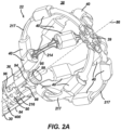
- FIG. 2A is an illustration of a perspective view of a medical probe 22 including a basket assembly 38 in an expanded form when unconstrained, such as by being advanced out of an insertion tube lumen at a distal end 39 of an insertion tube 30.
- Probe 22 may include a contact force sensor 400 to determine contact force of the spines against cardiac tissues. Details of the contact force sensor are shown and described in US Patent Application Publication No. US20210077180A1 published March 18, 2021 , which disclosure is incorporated by reference herein.
- the medical probe 22 illustrated in FIG. 2A lacks the guide sheath illustrated in FIG. 1 .
- spines 214 bow radially outwardly and in the collapsed form (not shown) the spines 214 are arranged generally along a longitudinal axis 86 of insertion tube 30.
- a plurality of electrically insulative jackets 217 is provided so that each jacket can be disposed between a respective spine 214 of the plurality of spines and a respective electrode 40 of the plurality of electrodes, thereby electrically isolating the plurality of electrodes from the plurality of spines.
- basket assembly 38 includes a plurality of flexible spines 214 that are formed at the end of a tubular shaft 84 and are connected at both ends.
- medical professional 34 can deploy basket assembly 38 by extending tubular shaft 84 from insertion tube 30 causing basket assembly 38 to exit insertion tube 30 and transition to the expanded form.
- Spines 214 may have elliptical e.g., circular, or rectangular that may appear to be flat cross-sections, and include a flexible, resilient material e.g., a shape-memory alloy such as nickel-titanium, also known as Nitinol forming a strut as will be described in greater detail herein. As shown in FIGS.
- basket assembly 38 has a proximal portion 36 and a distal end 39.
- the medical probe 22 can include a hub 90 that can function as a spine retention hub and/or an irrigation hub 90 that extends longitudinally from a distal end of tubular shaft 84 towards distal end 39 of basket assembly 38.
- control console 24 includes irrigation module 60 that delivers irrigation fluid to basket assembly 38 through tubular shaft 84.
- the plurality of flexible linear spines 214 converge at a central spine intersection 211 that is also disposed on a longitudinal axis 86 defined by the spines 214.
- central spine intersection 211 can include one or more cutouts 212 that allow for bending of the spines 214 when each spine respective attachment end 216 is connected to the spine retention hub 90, described in more detail below.
- electrodes 40 positioned on spines 114 of basket assembly 38 can be configured to deliver ablation energy RF and/or IRE to tissue in heart 26. Additionally, or alternatively, the electrodes can also be used to determine the location of basket assembly 38 and/or to measure a physiological property such as local surface electrical potentials at respective locations on tissue in heart 26.
- the electrodes 40 can be biased such that a greater portion of the one or more electrodes 40 face outwardly from basket assembly 38 such that the one or more electrodes 40 deliver a greater amount of electrical energy outwardly away from the basket assembly 38 i.e., toward the heart 26 tissue than inwardly.
- Examples of materials ideally suited for forming electrodes 40 include gold, platinum and palladium and their respective alloys. These materials also have high thermal conductivity which allows the minimal heat generated on the tissue i.e., by the ablation energy delivered to the tissue to be conducted through the electrodes to the back side of the electrodes i.e., the portions of the electrodes on the inner sides of the spines, and then to the blood pool in heart 26.
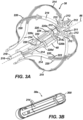
- Basket 38 includes a single unitary structure that includes a plurality of spines 214 formed from a cylindrical tube stock ( FIG. 3B ) and treated to cause the spines 214 to bias radially outward.
- the material for the spine 214 can be selected from a group consisting of nitinol, cobalt chromium, stainless steel, titanium, and combinations hereof.
- the spine retention hub 90 can be inserted into the tubular shaft 84 and attached to the tubular shaft 84.
- Spine retention hub 90 can include a cylindrical member 94 including a plurality of relief lands 96, multiple irrigation openings 98 to allow outflow of irrigation fluid into a volume defined by the basket spines, and hub end 99.
- Relief lands 96 can be disposed on the outer surface of cylindrical member 94 and configured to allow a portion of each spine 214, such as each spine attachment end 216, to be fitted into a respective relief land 96 of retention hub 90 also known as a coupler for a contact force sensor 400.
- the attachment end 216 can be a generally linear end of the spine 214.
- the attachment end 216 can be configured to extend outwardly from the spine retention hub 90 such that the basket assembly 38 is positioned outwardly from the spine retention hub 90 and, consequently, outwardly from the tubular shaft 84.
- the spine 214 can be configured to position the basket assembly 38 distally from the distal end of the tubular shaft 84 and distal from the distal end of the insertion tube 30 when the basket assembly 38 is deployed.
- Reference electrode 95 can be disposed on the projection 94 or on the hub end surface 99.
- hub 90 in effect can have multiple functions: (1) to retain the spine legs proximally; (2) allow hub 90 (as well as the basket assembly 22) to be connected to distal tube 84; (3) to function as a fluid diverter for irrigation fluid delivered through distal tube 84; and (4) provide a reference electrode 95.
- FIG. 2B a sectional view of the spines and electrodes are shown cut-away to show the spine frame 214 disposed inside jacket 217 with wiring 41 running along the spine frame 214 and extending through the jacket 217 to connect with the electrode 40 via connection point (e.g., solder pad) 43.
- FIG. 2C shows a perspective view of an opaque jacket 217 through which wirings 41 can be seen to extend through jacket to respective connection points 43 of electrodes 40.
- the connection point 43 is not required to be disposed inside the lumen 70 of electrode 40 but can be outside lumen 70 as long as the connection point does not interfere with tissue contact of the electrode 40.
- electrode 40 is about 2 mm to about 3 mm long with a width from about 1.5 mm to about 2.5 mm wide and a height of about 0.8 mm to about 1.5 mm.
- the lumen 70 may have a negative surface area of about 0.4 mm-squared to about 0.7 mm-squared.
- the lumen 70 is not placed at the geometrical center but is rather offset lower so that the center 86 of lumen 70 is more towards the flat bottom surface 76. This arrangement ensures that more of the top surfaces 78 and 80 of electrode 40 is above the lumen 70 than below lumen 70.
- electrode 40 can be located substantially in place with respect to spine 214 by way of a retention member 220 formed integrally with the spine 214.
- each of the spines 214 can include at least one retention member 220 extending generally transverse to the spine 214.
- each spine 214 can be bisected with a central spine member 222 so that empty space 224 is provided to allow retention member 220 to bend inwardly towards the central spine member 222.
- the shape of retention member 220 can be of any shape as along as such shape serves to allow the member 220 to be compressed for insertion into lumen 70 of electrode 40 and once released to prevent movement of electrode 40 with respect to the retention member 220.
- the at least one retention member 220 is shaped in a bow-like configuration with a center of such bow extending away from a periphery of spine 214.
- the at least one retention member 222 for each electrode 40 may include two bow shaped members 220 disposed in opposite direction and transverse to a longer length 214L of each spine 214.
- the at least one retention member may have first 220a, 220b and second sets 220c, 220d of retention members 220 spaced apart along the spines.
- the first set includes two bow shaped members 220a, 220b disposed in opposite direction and transverse to a longer length 214L of each spine 214 and the second set includes two bow shaped members 220c, 220d disposed in opposite direction and transverse to a longer length 214L of each spine 214 so that each electrode 40 is captured between the first and second sets of retention members 220a, 220b and 220c and 220d.
- FIG. 3B shows the spine structure 38a as formed from a tube stock. It is also within the scope of this invention for the spine structure 38a to be formed form a flat sheet stock, cut and heat treated to achieve the spheroidal basket shape shown herein.
- the spine structure 38a illustrated in FIG. 3B can be compressed longitudinally and the spines 214 can expand radially to form the basket shape spine structure illustrated in FIG. 3A of basket assembly 38 illustrated in FIG. 2A .
- FIGS. 4A and 4B show the distal portion 39 ( FIG. 2A ) in which the distal portion 39 of basket assembly 38 of medical probe 22 can be considered as being flattened between two flat sheets of glass.
- distal portion 39 defines a structure 300 resembling a cloverleaf and hence structure 300 will be referred hereafter as a "cloverleaf'.
- basket 38 in FIG. 4A and FIG. 4B has a plurality of spines 214 extending along the longitudinal axis 86 from a proximal central proximal spine portion 36 to a distal spine portion 39.
- the distal spine portion 39 defines a cloverleaf structure FIG. 4A , 300 disposed radially around the longitudinal axis 86.
- Each clover cutout 212 is aligned along radial axis A, B, C, D, E and F extending orthogonally from axis 86 so that the plurality of spines 214 extend from the proximal central spine portion 36 in an equiangular pattern such that respective angles between respectively adjacent spines are approximately equal. While the preferred embodiment includes six spines, it is within the scope of the invention to have any number of spines from four to twelve.
- the cloverleaf structure 300 also defines a central cutout C0 with a negative or empty area A0 disposed about the longitudinal axis 86.
- the cloverleaf structure 300 can be delineated by the following structures: a sinusoidal-like cloverleaf member 300 extending from one spine 214 to an adjacent spine 214 in a direction e.g., counterclockwise, or clockwise around the longitudinal axis 86. This characteristic of the sinusoidal structure 300 can be seen in FIG. 4B with for example, spine 214 located on radial axis A.
- a sinusoidal-like cloverleaf member 300 is configured so that it meanders as indicated by dashed line 302 around a portion of the cutout 212 having a negative or open first area A1 which can be approximated by circle R1.
- the term "open area” means the absence of any solid structure to define an empty space.
- This first open area A1 is approximately 20% that of the central area A0.
- the first open area A1 can be approximated by the first virtual circle R1 that has its center located at a first distance L1 to the longitudinal axis 86.
- the sinusoidal cloverleaf member 300 meanders in a counter-clockwise direction from axis A to axis F around a second open area A2 towards an adjacent spine 214 located on axis F.
- the second open area A2 can also be approximated to a second virtual circle R2 having a second open area A2 of approximately 90% of the first open area A1.
- the second virtual circle may have its center of radius R2 located at a second distance L2 smaller than the first distance L1 to the longitudinal axis 86.
- the sinusoidal cloverleaf member 300 meanders dashed line 302 around a third open area A3 which for convenience is approximated by third virtual circle with radius R3.
- the third virtual circle has its center for radius R3 located at a third distance L3 to the central axis 86 that is greater than L2 and approximately equal to the first distance L1.
- a width T0 of the spine 214 can be from 0.25 to 1 mm while the sinusoidal member 302 has a maximum width T1 of about 1 ⁇ 2 of the width of T0 with a minimum width T2 of about 1/3 of spine width T0.
- a width T3 proximate the spine axis (A, B, C, D, E or F) is about the same as the maximum with T1.
- the central area A0, approximated by radius R0, is approximately 0.8 mm-squared
- the fourth virtual circle C4 may have an area approximately 14 times greater than the central area A0.
- Each of the first and third virtual circle R1 and R3 is located at a first distance L1 of approximately 1.5 mm from the central axis 86 while the second virtual circle R2 is located at a distance L2 of approximately 1 ⁇ 2 that of the first distance L1.
- the plurality of spines 214 can be made from a material selected from a group consisting of nitinol, cobalt chromium, stainless steel, titanium, and combinations or alloys hereof.
- Each electrode 40 can be made of a material selected from stainless steel, cobalt chromium, gold, platinum, palladium, and alloys or combinations hereof.
- the inventors have devised the cloverleaf structure 300 in order to allow the basket assembly 38 to be compressed from a maximum diameter of the basket of approximately 12 mm to fit within an 8-12 French sheath without buckling or causing permanent plastic deformation to the spines 214 at any part of the basket assembly 38.
- the size of the sheath may be increased to up to 14.5 French to accommodate the additional spines.
- the sinusoidal-like cloverleaf member 300 is configured so that a portion of cloverleaf member 300 is tangential to the central circle C0 proximate a location between any two radial axes on which two neighboring spines 214 are located.
- the sinusoidal cloverleaf member 300 is tangential to the open circle C0 at a location bisecting the two radial axis A and B by a line Q1 connected to the central axis 86.
- This tangential characteristic of the sinusoidal cloverleaf member 300 around the open area A0 is repeated for any two adjacent spines 214 as spine 214 on axis B and spine 214 on axis C and so on for all of the bisecting axes Q1, Q2, Q3, Q4, Q5, Q6.
- the bisecting axes Q1, Q2, Q3, Q4 correspond to peaks of the sinusoidal cloverleaf member 300 and the radial axes A, B, C, D, E, F correspond to troughs of the sinusoidal cloverleaf, wherein peaks of the sinusoidal member are closer to the central axis 86 and troughs are further from the central axis 86.
- FIG. 3A Another notable feature of the basket structure 38 is a concavity 305 of the distal central portion 211 ( FIG. 3A ) that can be seen with reference to FIGS. 5A and 5B .
- FIG. 5A it can be seen that the cloverleaf structure 300 is bent so that its open center 211 is contiguous to a plane defined by central circle C0 and spaced apart by a gap G with respect to a plane defined by the fourth virtual circle C4 encircling the cloverleaf structure 300.
- the concavity is indicated by dashed line 305 representing the compound curvature generated by the cloverleaf structure 300 about the central axis 86.
- FIG. 6A illustrates the electrode 40 an end front view
- FIG. 6B illustrates the same electrode from a top-down perspective view of electrode 40, in accordance with an embodiment of the present invention.
- Each electrode 40 is fabricated from a biocompatible electrically conductive material, such as stainless steel, cobalt, chromium, platinum, palladium, iridium or gold and alloys or combinations of such metals.
- Each end (one shown in FIG. 6A ) of electrode 40 is provided with generally flat lands 82 surrounding a lumen 70 with curved outer surfaces 80 surrounding the lands 82.
- Electrode 40 has a tissue facing surface with a generally flat top surface 78 with curved outer perimeter 80 surrounding the generally flat top surface 78.
- each given electrode 40 has an inner surface 76 defined by its lumen 70 on which spine 214 can be inserted through the lumen 70.
- Electrical wire or electrical trace 41 FIG. 2C , sufficiently sized to deliver current pulses of at least 10 amps
- wire 41 is electrically connected to a connection point 43 on the inside surface 76 of lumen 70.
- the cross-section of the electrode can be ovoid, trapezoidal, or substantially ovoid or trapezoidal shape as shown in FIGS. 6A and 6B .
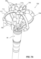
- FIGS. 7A and 7B illustrate another example basket catheter 728 with a basket assembly 738 having a plurality of electrodes 40a, 40b disposed on spines 714 and a hub 90 that can function similarly to the hub 90 illustrated in FIGS. 2A and 2B .
- the electrodes 40a, 40b can be disposed in alternating groupings of distal electrodes 40a and proximal electrodes 40b on adjacent spines 714.
- two electrodes 40a, 40b can be disposed on the spines 714 close to each other with no additional electrodes 40a, 40b disposed on the same spine 714.
- the two electrodes 40b can be disposed together near the proximal end of the spine 714 while on a second, adjacent spine 714 two electrodes 40a can be disposed together near the distal end of the adjacent spines 714.
- the electrodes 40a, 40b can be offset around the circumference of the basket catheter 728 such that the basket assembly 738 is better able to collapse when retracted into a sheath.
- the distal electrodes 40a are positioned entirely in a distal direction from the proximal electrodes 40b with a gap along the longitudinal axis 86 between the proximal electrodes 40b and the distal electrode 40a.
- the system 10 can be configured to output bipolar high-voltage DC pulses as may be used to effect irreversible electroporation (IRE) between the two adjacent electrodes 40a, 40b on a given spine 714, electrically connect the two adjacent electrodes 40a, 40b on a given spine 714 and output bipolar high-voltage DC pulses between one or more electrodes 40a, 40b on another one of the spines 714 of the basket assembly 738, and/or output monopolar high-voltage DC pulses between one or more of the electrodes 40a, 40b and the one or more electrode patches 44 ( FIG.
- bipolar high-voltage DC pulses as may be used to effect irreversible electroporation (IRE) between the two adjacent electrodes 40a, 40b on a given spine 714, electrically connect the two adjacent electrodes 40a, 40b on a given spine 714 and output bipolar high-voltage DC pulses between one or more electrodes 40a, 40b on another one of the spines 714 of the basket assembly 738, and/or
- the two electrodes 40a, 40b on a given spine 714 can include an insulative material 727 disposed between the two electrodes 40a, 40b, thereby electrically isolating the two electrodes 40a, 40b in an electrode pair from each other.
- the spines 714 can be covered with an insulative liner or jacket 717 that can be disposed between the electrodes 40a, 40b and the frame of the spines 714.
- the insulative liner 717 can electrically isolate the electrodes 40a, 40b from the frame of the spines 714 to prevent arcing or shorting to the frame of the spines 714.
- the insulative liner 717 can extend from the hub 90 to the distal end 39 of the basket assembly 738.
- FIG. 7B is an illustration of the basket assembly 738 with the insulative liners 717, a pair of distal electrodes 40a, and a pair of proximal electrodes 40b, and other spine elements removed, for the sake of illustration, so that the frame of the basket assembly 738 is visible.
- the spines 714 extend from the hub 90 and are joined together approximate a distal end 39 of the basket assembly 738 by a cloverleaf structure 300.
- the cloverleaf structure 300 can be configured similar to as disclosed in greater detail elsewhere herein, or a variation thereof.
- the insulative liner 717 can include flared ends 717a ( FIG. 7A ) that extend over a majority of the cloverleaf structure 300 ( FIG. 7B ) and may provide an atraumatic distal surface at the distal end 39 of the basket assembly 738. In this way, the insulative liner, or jacket 717 may prevent the frame of the basket assembly 738 from causing injury to tissue.
- the spines 714 can further include an electrode retention region 760a, 760b that is configured to prevent an electrode 40a, 40b from sliding proximally or distally along the spine 714.
- Adjacent spines 714 can have spine retention regions 760a, 760b alternating between a proximal position and a distal position along the spine 714. That is, a first spine 714 can have an electrode retention region 760b disposed near a proximal end of the spine 714 and an adjacent spine 714 can have an electrode retention region 760a disposed near a distal end of the spine 714.
- Each electrode retention region 760a, 760b can include one or more cutouts 764 that can permit the spine 714 to be bent or pinched inwardly.
- Each electrode retention region 760a, 760b can further include one or more retention members 762a-c that protrude outwardly and can be configured to prevent the electrode 40a, 40b from sliding proximally or distally along the spine 714.
- proximal ends of the frame of the basket assembly 738 are inserted into lumens of the electrodes 40a, 40b, and the electrodes 40a, 40b are slid distally along the spines 714 to their respective final position.
- the cutouts 764 permit the electrodes 40a, 40b to slide over a retention members 762a-c.
- the retention members 762a-c can be configured to move inwardly when the spine 714 is pinched inwardly to permit an electrode 40a, 40b to slide over the retention member 762a-c. Once the electrode 40a, 40b is slid past the retention member 762, the retention member 762 can resiliently bend back to its previous position, thereby preventing the electrode 40a, 40b from sliding proximally or distally along the spine 714.
- the proximal electrode retention region 760b includes a proximal retention member 762c and a distal retention member 762b.
- the proximal electrode retention region 760b need not be configured to permit the proximal electrodes 40b to pass over the distal retention member 762b.
- the distal electrode retention region 760a utilizes the cloverleaf structure 300 to prevent the distal electrodes 40a from moving distally once the distal electrodes 40a are in their respective final position.
- the basket catheter 728 is shown as having two electrodes 40a, 40b disposed near each other on a given spine 714 and having alternating groupings of electrodes 40a, 40b on adjacent spines 714, the disclosed technology can include other configurations of electrodes and spines not shown.
- the disclosed technology can include groupings of three or more electrodes and/or multiple groupings of electrodes disposed on spines, and may further include differing numbers of spines.
- the disclosed technology is not limited to the particular configuration of electrodes and spines shown and described herein.
Landscapes
- Health & Medical Sciences (AREA)
- Life Sciences & Earth Sciences (AREA)
- Surgery (AREA)
- Engineering & Computer Science (AREA)
- Plasma & Fusion (AREA)
- Medical Informatics (AREA)
- Otolaryngology (AREA)
- Physics & Mathematics (AREA)
- Cardiology (AREA)
- Biomedical Technology (AREA)
- Heart & Thoracic Surgery (AREA)
- Nuclear Medicine, Radiotherapy & Molecular Imaging (AREA)
- Molecular Biology (AREA)
- Animal Behavior & Ethology (AREA)
- General Health & Medical Sciences (AREA)
- Public Health (AREA)
- Veterinary Medicine (AREA)
- Surgical Instruments (AREA)
Applications Claiming Priority (3)
| Application Number | Priority Date | Filing Date | Title |
|---|---|---|---|
| US202263336023P | 2022-04-28 | 2022-04-28 | |
| US202263336094P | 2022-04-28 | 2022-04-28 | |
| US18/192,296 US20230346464A1 (en) | 2022-04-28 | 2023-03-29 | Basket catheter with cloverleaf structure to prevent buckling and retention feature for electrodes |
Publications (1)
| Publication Number | Publication Date |
|---|---|
| EP4268752A1 true EP4268752A1 (fr) | 2023-11-01 |
Family
ID=86272426
Family Applications (1)
| Application Number | Title | Priority Date | Filing Date |
|---|---|---|---|
| EP23170409.9A Pending EP4268752A1 (fr) | 2022-04-28 | 2023-04-27 | Cathéter à panier avec structure en trèfle pour empêcher le flambage et la rétention pour électrodes |
Country Status (3)
| Country | Link |
|---|---|
| US (1) | US20230346464A1 (fr) |
| EP (1) | EP4268752A1 (fr) |
| JP (1) | JP2023164371A (fr) |
Families Citing this family (6)
| Publication number | Priority date | Publication date | Assignee | Title |
|---|---|---|---|---|
| US12478424B2 (en) | 2021-09-10 | 2025-11-25 | Biosense Webster (Israel) Ltd. | Staggered pairs of biased ablation electrodes on basket catheter |
| US12484961B2 (en) | 2022-01-20 | 2025-12-02 | Biosense Webster (Israel) Ltd. | Mechanical retainer systems for electrodes of a basket catheter, and methods of the same |
| US12440263B2 (en) | 2022-01-20 | 2025-10-14 | Biosense Webster (Israel) Ltd. | Systems and methods for tripodic spines forming a spherical basket for improved tissue contact and current delivery |
| US20230346466A1 (en) * | 2022-04-28 | 2023-11-02 | Biosense Webster (Israel) Ltd. | Basket catheter with cloverleaf structure to provide predetermined lateral stiffness and axial strain |
| US12471989B2 (en) | 2022-04-28 | 2025-11-18 | Biosense Webster (Israel) Ltd. | Strengthened expandable baskets for medical probes and medical probes containing strengthen expandable baskets |
| US12533185B2 (en) | 2022-12-28 | 2026-01-27 | Biosense Webster (Israel) Ltd. | Basket end effector with distal position sensor |
Citations (12)
| Publication number | Priority date | Publication date | Assignee | Title |
|---|---|---|---|---|
| US20170319140A1 (en) * | 2016-05-06 | 2017-11-09 | Biosense Webster (Israel) Ltd. | Basket-shaped catheter with improved distal hub |
| US20210077180A1 (en) | 2019-09-12 | 2021-03-18 | Biosense Webster (Israel) Ltd. | Balloon Catheter with Force Sensor |
| US20210161592A1 (en) | 2019-12-03 | 2021-06-03 | Biosense Webster (Israel) Ltd. | Pulse Generator for Irreversible Electroporation |
| US20210162210A1 (en) | 2019-12-03 | 2021-06-03 | Biosense Webster (Israel) Ltd. | Using reversible electroporation on cardiac tissue |
| US20210169550A1 (en) | 2019-12-05 | 2021-06-10 | Biosense Webster (Israel) Ltd. | Generating and interleaving of irreversible-electroporation and radiofrequnecy ablation (ire/rfa) waveforms |
| US20210169567A1 (en) | 2019-12-09 | 2021-06-10 | Biosense Webster (Israel) Ltd. | Irreversible-electroporation (ire) balloon catheter with membrane-insulated high-voltage balloon wires |
| US20210169568A1 (en) | 2019-12-09 | 2021-06-10 | Biosense Webster (Israel) Ltd. | Oriented irreversible-electroporation (ire) pulses to compensate for cell size and orientation |
| US20210177503A1 (en) | 2019-12-11 | 2021-06-17 | Biosense Webster (Israel) Ltd. | Regulating delivery of irreversible electroporation pulses according to transferred energy |
| US20210186604A1 (en) | 2019-12-24 | 2021-06-24 | Biosense Webster (Israel) Ltd. | Irreversible electroporation (ire) based on field, contact force and time |
| US20210196372A1 (en) | 2019-12-31 | 2021-07-01 | Biosense Webster (Israel) Ltd. | Using irrigation on irreversible-electroporation (ire) electrodes to prevent arcing |
| WO2022001908A1 (fr) * | 2020-06-28 | 2022-01-06 | 杭州德诺电生理医疗科技有限公司 | Dispositif d'ablation et système d'ablation |
| US20220110679A1 (en) * | 2019-06-25 | 2022-04-14 | Hangzhou Noya Medtech Co., Ltd. | Atrial septostomy device |
Family Cites Families (3)
| Publication number | Priority date | Publication date | Assignee | Title |
|---|---|---|---|---|
| CN101309651B (zh) * | 2005-06-20 | 2011-12-07 | 麦德托尼克消融前沿有限公司 | 消融导管 |
| US20210307815A1 (en) * | 2020-04-07 | 2021-10-07 | Biosense Webster (Israel) Ltd. | Basket Catheter with Solid Conducting Spines as Electrodes for IRE |
| US20230346466A1 (en) * | 2022-04-28 | 2023-11-02 | Biosense Webster (Israel) Ltd. | Basket catheter with cloverleaf structure to provide predetermined lateral stiffness and axial strain |
-
2023
- 2023-03-29 US US18/192,296 patent/US20230346464A1/en active Pending
- 2023-04-27 JP JP2023073114A patent/JP2023164371A/ja active Pending
- 2023-04-27 EP EP23170409.9A patent/EP4268752A1/fr active Pending
Patent Citations (12)
| Publication number | Priority date | Publication date | Assignee | Title |
|---|---|---|---|---|
| US20170319140A1 (en) * | 2016-05-06 | 2017-11-09 | Biosense Webster (Israel) Ltd. | Basket-shaped catheter with improved distal hub |
| US20220110679A1 (en) * | 2019-06-25 | 2022-04-14 | Hangzhou Noya Medtech Co., Ltd. | Atrial septostomy device |
| US20210077180A1 (en) | 2019-09-12 | 2021-03-18 | Biosense Webster (Israel) Ltd. | Balloon Catheter with Force Sensor |
| US20210161592A1 (en) | 2019-12-03 | 2021-06-03 | Biosense Webster (Israel) Ltd. | Pulse Generator for Irreversible Electroporation |
| US20210162210A1 (en) | 2019-12-03 | 2021-06-03 | Biosense Webster (Israel) Ltd. | Using reversible electroporation on cardiac tissue |
| US20210169550A1 (en) | 2019-12-05 | 2021-06-10 | Biosense Webster (Israel) Ltd. | Generating and interleaving of irreversible-electroporation and radiofrequnecy ablation (ire/rfa) waveforms |
| US20210169567A1 (en) | 2019-12-09 | 2021-06-10 | Biosense Webster (Israel) Ltd. | Irreversible-electroporation (ire) balloon catheter with membrane-insulated high-voltage balloon wires |
| US20210169568A1 (en) | 2019-12-09 | 2021-06-10 | Biosense Webster (Israel) Ltd. | Oriented irreversible-electroporation (ire) pulses to compensate for cell size and orientation |
| US20210177503A1 (en) | 2019-12-11 | 2021-06-17 | Biosense Webster (Israel) Ltd. | Regulating delivery of irreversible electroporation pulses according to transferred energy |
| US20210186604A1 (en) | 2019-12-24 | 2021-06-24 | Biosense Webster (Israel) Ltd. | Irreversible electroporation (ire) based on field, contact force and time |
| US20210196372A1 (en) | 2019-12-31 | 2021-07-01 | Biosense Webster (Israel) Ltd. | Using irrigation on irreversible-electroporation (ire) electrodes to prevent arcing |
| WO2022001908A1 (fr) * | 2020-06-28 | 2022-01-06 | 杭州德诺电生理医疗科技有限公司 | Dispositif d'ablation et système d'ablation |
Also Published As
| Publication number | Publication date |
|---|---|
| US20230346464A1 (en) | 2023-11-02 |
| JP2023164371A (ja) | 2023-11-10 |
Similar Documents
| Publication | Publication Date | Title |
|---|---|---|
| EP4268750B1 (fr) | Paniers extensibles renforcés pour sondes médicales et sondes médicales contenant des paniers extensibles renforcés | |
| EP4268746A1 (fr) | Cathéter panier avec capteur de force à montage à baïonnette | |
| EP4268752A1 (fr) | Cathéter à panier avec structure en trèfle pour empêcher le flambage et la rétention pour électrodes | |
| US20230346459A1 (en) | Basket catheter with force sensor having bayonet mount | |
| US20230301712A1 (en) | Elongated trapezoidal electrodes of a basket catheter and methods of making the same | |
| EP4268747B1 (fr) | Cathéter à panier avec structure en trèfle pour fournir une rigidité latérale prédéterminée et une contrainte axiale | |
| US20230226336A1 (en) | Electrode assemblies of a basket catheter having mechanical retainers and methods of the same | |
| US12440263B2 (en) | Systems and methods for tripodic spines forming a spherical basket for improved tissue contact and current delivery | |
| US20230225783A1 (en) | Systems and methods for a single spiral electrode assembly forming a spherical basket for improved tissue contact and current delivery | |
| US20230225788A1 (en) | Systems and methods for c-shaped spines forming a spherical basket for improved tissue contact and current delivery | |
| CN220588341U (zh) | 医疗探头 | |
| CN116999148A (zh) | 具有带卡口安装件的力传感器的篮式导管 | |
| US12616519B2 (en) | Basket assembly with atraumatic tip electrode and methods of making thereof | |
| CN220655660U (zh) | 医疗探头 | |
| CN220477646U (zh) | 用于医疗探头的可膨胀篮式组件和医疗探头 | |
| US20240197391A1 (en) | Basket assembly with atraumatic tip electrode and methods of making thereof | |
| EP4268749A1 (fr) | Systèmes et dispositifs pour un écoulement d'irrigation amélioré pendant une procédure cardiaque | |
| EP4473928A1 (fr) | Ensembles panier extensibles et ensembles panier extensibles avec soulagement de contrainte de fil d'électrode | |
| IL309671A (en) | A basket catheter with a trefoil-like structure to provide predetermined lateral stiffness and axial tension |
Legal Events
| Date | Code | Title | Description |
|---|---|---|---|
| PUAI | Public reference made under article 153(3) epc to a published international application that has entered the european phase |
Free format text: ORIGINAL CODE: 0009012 |
|
| STAA | Information on the status of an ep patent application or granted ep patent |
Free format text: STATUS: THE APPLICATION HAS BEEN PUBLISHED |
|
| AK | Designated contracting states |
Kind code of ref document: A1 Designated state(s): AL AT BE BG CH CY CZ DE DK EE ES FI FR GB GR HR HU IE IS IT LI LT LU LV MC ME MK MT NL NO PL PT RO RS SE SI SK SM TR |
|
| STAA | Information on the status of an ep patent application or granted ep patent |
Free format text: STATUS: REQUEST FOR EXAMINATION WAS MADE |
|
| 17P | Request for examination filed |
Effective date: 20240429 |
|
| RBV | Designated contracting states (corrected) |
Designated state(s): AL AT BE BG CH CY CZ DE DK EE ES FI FR GB GR HR HU IE IS IT LI LT LU LV MC ME MK MT NL NO PL PT RO RS SE SI SK SM TR |