EP4268765B1 - Gaine pour une pointe d'un dispositif de balayage et système associé - Google Patents
Gaine pour une pointe d'un dispositif de balayage et système associé Download PDFInfo
- Publication number
- EP4268765B1 EP4268765B1 EP23189714.1A EP23189714A EP4268765B1 EP 4268765 B1 EP4268765 B1 EP 4268765B1 EP 23189714 A EP23189714 A EP 23189714A EP 4268765 B1 EP4268765 B1 EP 4268765B1
- Authority
- EP
- European Patent Office
- Prior art keywords
- sheath
- tip
- optical window
- scanning device
- optical
- Prior art date
- Legal status (The legal status is an assumption and is not a legal conclusion. Google has not performed a legal analysis and makes no representation as to the accuracy of the status listed.)
- Active
Links
Images





Classifications
-
- A—HUMAN NECESSITIES
- A61—MEDICAL OR VETERINARY SCIENCE; HYGIENE
- A61B—DIAGNOSIS; SURGERY; IDENTIFICATION
- A61B1/00—Instruments for performing medical examinations of the interior of cavities or tubes of the body by visual or photographical inspection, e.g. endoscopes; Illuminating arrangements therefor
- A61B1/00142—Instruments for performing medical examinations of the interior of cavities or tubes of the body by visual or photographical inspection, e.g. endoscopes; Illuminating arrangements therefor with means for preventing contamination, e.g. by using a sanitary sheath
-
- A—HUMAN NECESSITIES
- A61—MEDICAL OR VETERINARY SCIENCE; HYGIENE
- A61B—DIAGNOSIS; SURGERY; IDENTIFICATION
- A61B1/00—Instruments for performing medical examinations of the interior of cavities or tubes of the body by visual or photographical inspection, e.g. endoscopes; Illuminating arrangements therefor
- A61B1/00064—Constructional details of the endoscope body
- A61B1/00071—Insertion part of the endoscope body
- A61B1/0008—Insertion part of the endoscope body characterised by distal tip features
- A61B1/00096—Optical elements
-
- A—HUMAN NECESSITIES
- A61—MEDICAL OR VETERINARY SCIENCE; HYGIENE
- A61B—DIAGNOSIS; SURGERY; IDENTIFICATION
- A61B1/00—Instruments for performing medical examinations of the interior of cavities or tubes of the body by visual or photographical inspection, e.g. endoscopes; Illuminating arrangements therefor
- A61B1/00064—Constructional details of the endoscope body
- A61B1/00071—Insertion part of the endoscope body
- A61B1/0008—Insertion part of the endoscope body characterised by distal tip features
- A61B1/00101—Insertion part of the endoscope body characterised by distal tip features the distal tip features being detachable
-
- A—HUMAN NECESSITIES
- A61—MEDICAL OR VETERINARY SCIENCE; HYGIENE
- A61B—DIAGNOSIS; SURGERY; IDENTIFICATION
- A61B1/00—Instruments for performing medical examinations of the interior of cavities or tubes of the body by visual or photographical inspection, e.g. endoscopes; Illuminating arrangements therefor
- A61B1/00064—Constructional details of the endoscope body
- A61B1/00103—Constructional details of the endoscope body designed for single use
-
- A—HUMAN NECESSITIES
- A61—MEDICAL OR VETERINARY SCIENCE; HYGIENE
- A61B—DIAGNOSIS; SURGERY; IDENTIFICATION
- A61B1/00—Instruments for performing medical examinations of the interior of cavities or tubes of the body by visual or photographical inspection, e.g. endoscopes; Illuminating arrangements therefor
- A61B1/00064—Constructional details of the endoscope body
- A61B1/0011—Manufacturing of endoscope parts
-
- A—HUMAN NECESSITIES
- A61—MEDICAL OR VETERINARY SCIENCE; HYGIENE
- A61B—DIAGNOSIS; SURGERY; IDENTIFICATION
- A61B1/00—Instruments for performing medical examinations of the interior of cavities or tubes of the body by visual or photographical inspection, e.g. endoscopes; Illuminating arrangements therefor
- A61B1/00131—Accessories for endoscopes
- A61B1/00135—Oversleeves mounted on the endoscope prior to insertion
-
- A—HUMAN NECESSITIES
- A61—MEDICAL OR VETERINARY SCIENCE; HYGIENE
- A61B—DIAGNOSIS; SURGERY; IDENTIFICATION
- A61B1/00—Instruments for performing medical examinations of the interior of cavities or tubes of the body by visual or photographical inspection, e.g. endoscopes; Illuminating arrangements therefor
- A61B1/00163—Optical arrangements
- A61B1/00174—Optical arrangements characterised by the viewing angles
- A61B1/00179—Optical arrangements characterised by the viewing angles for off-axis viewing
-
- A—HUMAN NECESSITIES
- A61—MEDICAL OR VETERINARY SCIENCE; HYGIENE
- A61B—DIAGNOSIS; SURGERY; IDENTIFICATION
- A61B1/00—Instruments for performing medical examinations of the interior of cavities or tubes of the body by visual or photographical inspection, e.g. endoscopes; Illuminating arrangements therefor
- A61B1/24—Instruments for performing medical examinations of the interior of cavities or tubes of the body by visual or photographical inspection, e.g. endoscopes; Illuminating arrangements therefor for the mouth, i.e. stomatoscopes, e.g. with tongue depressors; Instruments for opening or keeping open the mouth
-
- A—HUMAN NECESSITIES
- A61—MEDICAL OR VETERINARY SCIENCE; HYGIENE
- A61C—DENTISTRY; APPARATUS OR METHODS FOR ORAL OR DENTAL HYGIENE
- A61C1/00—Dental machines for boring or cutting ; General features of dental machines or apparatus, e.g. hand-piece design
- A61C1/08—Machine parts specially adapted for dentistry
- A61C1/16—Protecting caps for hand-pieces or angle-pieces
-
- A—HUMAN NECESSITIES
- A61—MEDICAL OR VETERINARY SCIENCE; HYGIENE
- A61B—DIAGNOSIS; SURGERY; IDENTIFICATION
- A61B1/00—Instruments for performing medical examinations of the interior of cavities or tubes of the body by visual or photographical inspection, e.g. endoscopes; Illuminating arrangements therefor
- A61B1/227—Instruments for performing medical examinations of the interior of cavities or tubes of the body by visual or photographical inspection, e.g. endoscopes; Illuminating arrangements therefor for ears, i.e. otoscopes
-
- A—HUMAN NECESSITIES
- A61—MEDICAL OR VETERINARY SCIENCE; HYGIENE
- A61B—DIAGNOSIS; SURGERY; IDENTIFICATION
- A61B5/00—Measuring for diagnostic purposes; Identification of persons
- A61B5/0059—Measuring for diagnostic purposes; Identification of persons using light, e.g. diagnosis by transillumination, diascopy, fluorescence
- A61B5/0082—Measuring for diagnostic purposes; Identification of persons using light, e.g. diagnosis by transillumination, diascopy, fluorescence adapted for particular medical purposes
- A61B5/0084—Measuring for diagnostic purposes; Identification of persons using light, e.g. diagnosis by transillumination, diascopy, fluorescence adapted for particular medical purposes for introduction into the body, e.g. by catheters
- A61B5/0086—Measuring for diagnostic purposes; Identification of persons using light, e.g. diagnosis by transillumination, diascopy, fluorescence adapted for particular medical purposes for introduction into the body, e.g. by catheters using infrared radiation
-
- A—HUMAN NECESSITIES
- A61—MEDICAL OR VETERINARY SCIENCE; HYGIENE
- A61C—DENTISTRY; APPARATUS OR METHODS FOR ORAL OR DENTAL HYGIENE
- A61C9/00—Impression cups, i.e. impression trays; Impression methods
- A61C9/004—Means or methods for taking digitized impressions
- A61C9/0046—Data acquisition means or methods
- A61C9/0053—Optical means or methods, e.g. scanning the teeth by a laser or light beam
Definitions
- the sheath comprises a hollow body comprising a distal sheath-end, a proximal sheath-end, and a sheath-side wall located between the distal sheath-end and the proximal sheath-end, wherein the proximal sheath-end forms a sheath-opening that is dimensioned with respect to at least the part of the tip.
- the optical window has a thickness of more than 400 microns. Accordingly, in most embodiments, the optical window is non-flexible, meaning that the optical window may not, when mounted to or located in the sheath-side wall, bend or similarly deform, at least not easily.
- the optical material may be made of a material that is defined to flexible under certain circumstances. For example, if high pressure is applied to an optical window with a thickness of more than 400 microns, then the window may under such circumstance bend or similarly deform.
- the present invention allows for 3D intraoral scanning with a 3D intraoral scanning device comprising an internal light source that project lights and acquires images through the same optical element, such that no internal reflections are acquired during scanning and/or without altering the polarization during scanning and at the same time such that scanning device does not get contaminated from the outside environment.
- optical window may also be sealed and provides thereby no entrance into the hollow body.
- the optical window is according to the invention located on or mounted to the sheath-side wall, whereby the scanning device is able to scan to a side, rather than scanning in a forward direction.
- the proximal sheath-end of the hollow body may comprise a closed surface such that contamination from the outside is impossible through the proximal sheath-end.
- the sheath i.e. the hollow body may be able to be replaceably fit around at least a part the tip of the scanning device, thereby reducing contamination even further.
- the hollow body may in some embodiment also able to replaceably fit around a part of the scanning device, and in some embodiments, the entire scanning device. This provides that contamination to the intraoral scanning device is also avoided. Particularly, by having the hollow body covering both the tip and part of the intraoral scanning device, contamination to the part between the intraoral scanning device and the tip is avoided.
- the sheath according to the present invention is in most embodiments configured for being disposable and configured to be single-used. Accordingly, the sheath may be made of environmentally friendly materials.
- the present invention provides in a second aspect a system of an intraoral scanning device, comprising: a tip of an intraoral scanning device comprising an optical aperture; and a sheath configured for being replaceably mounted to at least a part of the tip of the intraoral scanning device, thereby being configured to be used in combination with the scanning device to scan an oral cavity.
- the sheath comprises: a hollow body comprising, a distal sheath-end, a proximal sheath-end, and a sheath-side wall located between the distal sheath-end and the proximal sheath-end, wherein the proximal sheath-end forms a sheath-opening that is dimensioned with respect to at least a part of the tip.
- the sheath comprises an optical window mounted to or located in the sheath-side wall near the distal sheath-end such that when the sheath is replaceably mounted to at least the part of the tip via the sheath-opening, the optical window covers at least a part of an optical aperture of the tip.
- the optical window is made of a material configured for not substantially altering the polarization of the light that exits and enters the intraoral scanning device trough the optical aperture of the tip and through the optical window to and from the intraoral cavity.
- the optical window ensures that the scanning device provides substantially the same scan of the intraoral cavity regardless of the sheath being replaceably mounted to at least the part of the tip or not.
- the optical window has a thickness of more than 400 microns.
- an optimal thickness of the optical window is more than 400 microns because, when more than this, the optical window is able to cover the field-of-view that is typically used in intraoral scanning without being deformed during intraoral scanning. If the optical window would be less than 400 microns, the optical window could easily bend, and this could introduce internal reflections by the optical window that could compromise the imaging quality of the intraoral scanning device. In some cases, when much less than 400 microns, the optical window could even tend to ripple, which severely could compromise the imaging quality of the intraoral scanning device. Accordingly, the inventors found the thickness of more than 400 microns to be an optimal thickness to provide optimal imaging in an intraoral scanning device.
- the thickness of more than 400 microns may also ensure that the optical window does not break during scanning.
- the scanning tip very often comes into contact with teeth, sometimes even sharp teeth, and if there is a window of less than 400 microns, such window could easily break and splinter into the mouth of a patient.
- the optical window could even tend to puncture or crack.
- Such scenarios must be avoided and therefore a solution to the scenario may be to provide the optical window with a thickness of more than 400 microns.
- the optical window is made of a material configured for not substantially altering the polarization. This is also the case when introducing a window with a thickness of more than 400 microns. Where many materials with a thickness of less than 400 microns may not alter the polarization, many materials with of a thickness of more than 400 microns may indeed alter the polarization.
- the material when introducing the window with a thickness of more than 400 microns, the material must be carefully selected such that it does not substantially alter the polarization and/or introduces internal reflection.
- the window with a thickness of more than 400 microns one therefore must carefully consider both the effect of the selected material and the thickness of the optical window.
- the thickness of the optical window is more than 600 microns or more than 800 microns, or more than 1000 microns. The inventors have found that when introducing these thicknesses, the optical window becomes more stable and is less prone to break, particularly when being used to intraorally scan the intraoral cavity with an intraoral scanner having thereon the sheath of the present invention.
- the thickness may be between 400 microns and 5000 microns. In preferred embodiments, the thickness may be between 800 microns and 2000 microns.
- the thickness is selected to not substantially deform the optical window during the scan of the oral cavity. Examples of scenarios with deformation and examples of the thicknesses that provide the solution to avoid the scenarios have been described above.
- the material of the optical window has a hardness that is selected to withstand the impact of teeth in the intraoral cavity.
- the optical window is made of a material, wherein the material is configured for not substantially altering the polarization of the light that exits and enters via the optical window.
- the material of the optical window may be selected to be one or more polymer(s).
- a polymer may combine the optical characteristics of glass with the design-freedom of a molded or extruded plastic. Further, a polymer may be advantageous because inorganic nanocrystals can be added to the polymer(s).
- a polymer may be defined to flexible, at least in free-form, and at least when the polymer(s) form(s) a window that is less than 400 microns thick and more than 10 square mm.
- a polymer may be said to be non-flexible when at least the thickness is more than 400 microns. More generally, when an optical window is located to or mounted in the sheath, the optical window typically is in a state, where it can be defined to be non-flexible.
- the optical window may be made of glass and/or quarts.
- the optical window may have some degree of birefringence, whereby the optical window is within the context of being configured such that it not substantially alters the polarization of the light.
- the optical refractive index (known as n o and n e ) along the two optical directions inside the optical window may differ by up to 15% to not substantially alter the polarization of the light.
- 3D scanning may be substantially unaffected by the window.
- the optical refractive index along the two optical directions inside the window may differ between 0.1% and 14%, such as between 0.4% and 10%, such as between 1% and 5%.
- the optical refractive index along the two optical directions may be less than 15%, such as less than 10%, such as less than 6%, such as less than 3%, or such as less than 1%.
- Birefringence can be quantified in units nm/cm, i.e. optical path length (in nm) over materials thickness (in cm).
- Optical quality glass is in the range 2-20 nm/cm.
- the optical window may be defined to have a birefringence of around 2500 nm/cm.
- the optical window is glued, or sealed, or welded into the hollow body.
- Polarization may be affected by the structure of the surface, and thus in most embodiments, the optical window is planar and/or comprises a planar surface. This may contribute to not altering the polarization of the light.
- the optical window is a non-flexible optical window mounted in the body.
- a non-flexible window may in some embodiments be realized by suspending a flexible window inside a non-flexible frame, for example a frame made of stainless steel or another rigid material.
- At least a part of the optical window is dimensioned to mechanically couple to a coupling unit on the tip.
- This embodiment allows the surface normal to deviate from the optical axis, whereby internal reflections of the light that exits via the tip is guided away from the optical axis. Further, this embodiment allows the window to be means for coupling to the tip.
- an advantage of this embodiment is that the optical window provides the mounting of the sheath to the tip.
- the optical window comprises a hydrophilic surface.
- a hydrophilic surface is the avoidance of water droplet formation on the window, for example due to fogging in a humid environment, for example from the breath of a patient.
- the hydrophilic surface may be realized by a hydrophilic coating or as an intrinsic property of the optical window.
- the optical window is treated with an anti-fog agent, for example in the form a coating.
- the optical window is configured to absorb light in the near infrared domain and/or in the lower visible domain.
- An advantage of such a configuration is that that window may be heating via optical means. This may be an alternative to having a hydrophilic window as heating can also prevent water droplets forming on the window.
- the hollow body is flexible.
- the optical window may adapt to an angled surface of the tip because the flexible hollow body provides for such an adaption.
- the optical window may be mounted on the flexible body such that when the optical window is non-flexible, the optical window is allowed to be angled by pulling the flexible hollow body, the flexible hollow body may be elastic or non-elastic to allow for such angling.
- the hollow body is non-flexible, i.e. rigid.
- a rigid hollow body may be obtained by injection-molding.
- a non-flexible hollow body has the advantage of being handled more easily especially when the hollow body needs to be put onto the tip.
- the hollow body is semi-flexible, such that the body may self-support its own shape, but at the same time flexible enough to adapt to the scanner tip and/or part of the scanning device, for example to ensure a tight fit.
- a semi-flexible structure can, for example, be obtained by blow-molding a polymer material.
- the hollow body is made of one or more polymer(s). In some embodiments, the hollow body is made of the same material as the optical window.
- the hollow body is made of a polyester resin composition and a polycarbonate resin composition.
- the sheath is made of one or more material(s) that is/are adapted to be inserted into the intraoral cavity.
- the system comprises a sheath and a tip.
- the sheath is the sheath according to first aspect as described above.
- the tip comprises a tip-body configured to allow light to exit and enter the intraoral scanning device to and from an intraoral cavity trough the aperture, wherein the tip-body comprises a proximal tip-end, a distal tip-end, and a tip-side wall located between the proximal tip-end and the distal tip-end, wherein the proximal tip-end forms an opening that is mounted to or located in the intraoral scanning device, and wherein the aperture is located in the tip-side wall near the distal tip-end.
- a tip may be configured for scanning through the tip side wall, which makes scanning of intraoral cavities easier than scanning though a distal tip-end.
- the tip comprises a mirror inside the tip-body, wherein the mirror is configured to direct the light from the intraoral scanning device and to the intraoral cavity via the optical aperture and back the same way into the intraoral scanning device.
- the optical aperture of the tip allows for mechanical access into the tip-body such that when the sheath is replaceably mounted to at least the part the tip via the sheath-opening, then the sheath blocks the mechanical access. This prevents contamination of the inside of the tip.
- the tip is configured for being replaceably mounted to the intraoral scanning device.
- contamination of the scanning device is reduced to a minimum.
- the scanning device itself need not to be sterilized, such as for example in an autoclave.
- the invention provides with this embodiment for effectively avoiding contamination of the scanning device.
- the tip comprises an optical axis, where a mirror is located on the optical axis such that the optical axis is redirected inside the tip. This may allow for the scanning device to scan to the side rather than in a forward direction.
- the tip comprises a coupling unit that is dimensioned to mechanically couple at least a part of the optical window to the tip.
- This embodiment allows the surface normal to deviate from the optical axis, whereby internal reflections of the light that exits via the tip is guided away from the optical axis. Further, this embodiment allows the window to be means for coupling to the tip.
- an advantage of this embodiment is that the optical window provides the mounting of the sheath to the tip.
- the coupling unit is configured such that when the optical window is mounted to the tip, the surface normal of the optical window deviates from the optical axis of more than 5 degrees, such as more than 10 degrees, such as between 10 and 30 degrees, such as between 10 and 20 degrees, such as between 10 and 15 degrees, such as around 12 degrees, such as around 11.5 degrees and/or such as around 12.5 degrees. This allows for a reflected spot to be directed out of the sensor area.
- the internally reflected light is not guided directly back on the optical axis as the case would be if the surface normal would be parallel to the optical axis.
- the internally reflected light is not guided towards an imaging sensor in the scanning device and avoids the use of anti-reflective coating.
- internally reflected light is guided out of the sensor area by having the surface normal of the optical window angled relative to the optical axis.
- the sheath may have an angled surface, whereon the optical window is mounted.
- the tip may have an angled surface, whereon the optical window is mounted.
- the optical window may adapt to the angled surface of the tip because the flexible body provides for such an adaption.
- the optical window may be mounted on the flexible body such that the optical window is allowed to be angled by pulling the flexible body.
- the flexible body may be elastic or non-elastic to allow for such angling.
- the coupling unit is a slit or a groove, wherein the slit or groove has a height larger than a thickness of the optical window, and/or wherein the slit or groove has a length and/or width that is less than the length and/or width of the optical window, such as a half of the optical window, or such as a third of the optical window, or such as a tenth of the optical window.
- the specified thickness allows for the optical window to fit into the slit and the specified length and/or width allows for saving material, such that the sheath can be manufactured with low cost.
- the coupling unit is located around a part of the aperture such that the optical window is able to be coupled on top of the aperture. This allows for light to exit and enter the optical axis via the aperture and the optical window, especially such that the aperture gets closed, whereby contamination is avoided.
- the system further comprises the intraoral scanner.
- the intraoral scanner is configured for forming a 3D model of the intraoral objects such as teeth and gingiva.
- the intraoral scanner comprises a light source to emit light, for example to project a pattern onto the intraoral objects, whereby this pattern is used by imaging of the intraoral scanning device to form the 3D model.
- the intraoral scanner is configured to emit the light as linearly polarized light.
- the intraoral scanner is configured to emit the light as circularly polarized light.
- the circularly polarized light when the circularly polarized light is specularly reflected from the intraoral objects, the helicity of the polarization changes, for example from right hand circular polarized to left hand circular polarized. Accordingly, circular polarized light is received at the optical window of the sheath, and to image the specular reflections, the scanner is configured, for example by comprising a quarter wave retarder, to only allow light with circular polarized light to pass into the imaging device.
- optical window of the sheath according to the invention does not substantially alter the polarization - if it did, the result of the 3D model would be very dramatically changed and would possibly not be precise enough for use in relation with a tooth restoration or other important operations that are governed by a 3D model.
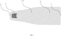
- Example 1 A flexible sheath as shown from a top-view
- Fig. 1 shows an example of the sheath (1) according to the invention from a top-view.
- Fig. 1 shows a sheath (1) for a tip (2) of a scanning device (3), comprising: a body (4) in the form of a tubular member (5) comprising a distal end (6) and a proximal end (7).
- the proximal end (7) comprises an opening (8) that is dimensioned with respect to at least the tip (2) of the scanning device (3), such that the tubular member (5) is able to be replaceably mounted to at least a part of the tip (2) of the scanning device (3).
- the body (4) comprises a non-flexible optical window (9) mounted in the body between the distal end (6) and the proximal end (7) of the body, such that the optical window (9) allows for light to exit and to enter the scanning device (3) via an optical axis (10) inside the tip (2).
- the optical window (9) is mounted in the body (4) such that when the tubular member (5) is replaceably fit around at least the tip (2) of the scanning device (3), the optical window (9) comprises a surface normal (11) that deviates from the optical axis (10), whereby internal reflections of the light that exits via the tip (2) is guided away from the optical axis (10).
- the optical window (9) is made of a material, wherein the material is configured for not substantially altering the polarization of the light that exits and enters via the optical window (9).
- a great advantage of a flexible body is that it has very low volume when packed, especially because the body (4) is flat when not attached to the tip (2) of the scanning device (3).
- the optical window is formed such that when the body (4) is replaceably fit around at least the tip (2) of the scanning device (3), the optical window (9) comprises a surface normal (11) that deviates from the optical axis (10), whereby internal reflections of the light that exits via the tip (2) is guided away from the optical axis (10).
- the optical window is configured such that when the body (4) is replaceably fit around at least the tip (2) of the scanning device (3), the optical window (9) comprises a surface normal (11) that deviates from the optical axis (10), whereby internal reflections of the light that exits via the tip (2) is guided away from the optical axis (10).
- Fig. 3 shows an example of a tip (2) for the scanning device (3) according to the second aspect of the invention, shown from the outside.
- the tip (2) comprises a mirror (15) located on the optical axis (10) such that the optical axis (10) is redirected inside the tip (2).
- the mirror (15) and optical axis (10) cannot be seen in this figure, since only the outside is shown. However, this can be seen in the next figure, Fig. 4 .
- the tip (2) comprises a coupling unit (16) that is dimensioned to mechanically couple at least a part of the optical window (9) to the tip.
- the coupling unit (16) is configured such that when the optical window (9) is mounted to the tip (2), the surface normal (11) of the optical window (9) deviates from the optical axis (10) of around 11.5 degrees.
- the surface normal (11) of the optical window (9) deviates from the optical axis by and angle referred to as ⁇ . This is clearly shown in Fig. 4 .
- the coupling unit (16) is a groove, wherein the groove has a height larger than a thickness of the optical window (9).
- the groove has a length and/or width that is less than the length and/or width of the optical window, here around a tenth of the optical window.
- the coupling unit (16) is located around a part of the aperture (14) such that the optical window (9) is able to be coupled on top of the aperture (14), i.e. on the outside of the aperture (14).
- the tip (2) comprises a locking mechanism (17) for the optical window (9), in this example a snap-lock, whereon the part (13) of the optical window (9) matches.
- the tip (2) may be an injection-molded tip.
- Example 4 A tip of a scanning device as shown from the inside
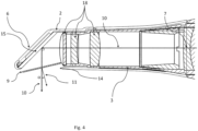
- Fig. 4 shows an example of a tip (2) for the scanning device (3) according to the second aspect of the invention, shown from the inside. Parts of the sheath are also shown in relation to parts of the tip (2)- for seeing these parts in relation to each other.
- Fig. 4 shows a tip (2) for the scanning device (3), wherein the tip is replaceably mountable on the scanning device (3), the tip comprising an aperture (14) on an optical axis (10) such that light is allowed to exit and to enter the scanning device via the optical axis (10).
- Optical elements (18) are shown to reside inside the scanning device (3).
- the tip (2) comprises a mirror (15) located on the optical axis (10) such that the optical axis (10) is redirected inside the tip (2).
- the mirror (15) and optical axis (10) are clearly seen here in Fig. 4 .
- the mirror is tilted 45 degrees relative to the optical axis (10).
- the optical axis is directed such that the optical axis comprises two optical axes that are perpendicular to each other, however the two optical axes defining the optical system of the scanning device.
- the mirror is tilted less or more than 45 degrees relative to the optical axis (10), for example such that the light exits the aperture at an angle which is different from being perpendicular to the optical axis along the body, i.e. the optical axis going from the proximal end (7) to the distal end (6).
- the tip (2) comprises a coupling unit (16) that is dimensioned to mechanically couple at least a part of the optical window (9) to the tip.
- the coupling unit (16) is configured such that when the optical window (9) is mounted to the tip (2), the surface normal (11) of the optical window (9) deviates from the optical axis (10) of around 11.5 degrees.
- the surface normal (11) of the optical window (9) deviates from the optical axis by and angle referred to as ⁇ . This is clearly shown in Fig. 4 .
- the optical window can be placed flush with the tip (2), i.e. parallel to the optical axis (10) along the body (4), i.e. the optical axis (10) going from the proximal end to the distal end. In this manner, the surface normal (11) of the optical window (9) would also deviate from the optical axis (10).
- Example 5 - A system comprising a sheath for a tip of an intraoral scanning device, shown as un-mounted
- Fig. 5 shows a system of an intraoral scanning device (3), comprising: the sheath (1) as shown in Fig. 1 , a tip (2) for the intraoral scanning device (3), wherein the tip (2) is replaceably mountable on the intraoral scanning device (3).
- the tip (2) comprises an aperture (14) on an optical axis such that light is allowed to exit and to enter the intraoral scanning device (3) via the optical axis (10).
- the sheath (1), the tip (2) and the scanning device (3) are shown as unmounted from each other.
- Example 6 - A system comprising a sheath for a tip of a scanning device, shown as mounted
- Fig. 6 shows a system of an intraoral scanning device (3), comprising: the sheath (1) as shown in Fig. 1 , a tip (2) for the intraoral scanning device (3), wherein the tip (2) is replaceably mounted on the scanning device (3).
- the tip (2) comprises an aperture (14) on an optical axis such that light is allowed to exit and to enter the scanning device (3) via the optical axis (10).
- the sheath (1), the tip (2) and the scanning device (3) are shown as mounted to each other.
- Example 7 A semi-flexible sheath as shown from a perspective view
- Fig. 7 shows another example of the sheath (1) according to the invention.
- Fig. 7 shows a semi-flexible sheath (1) for a tip (2) of a scanning device (3), comprising: a semi-flexible body (4) comprising a distal end (6) and a proximal end (7).
- the proximal end (7) comprises an opening (8) that is dimensioned with respect to at least the tip (2) of the scanning device (3), such that the body (4) is able to replaceably fit around at least a part of the tip (2) of the scanning device (3).
- the body (4) comprises a non-flexible optical window (9) mounted in the body between the distal end (6) and the proximal end (7) of the body, such that the optical window (9) allows for light to exit and to enter the scanning device (3) via an optical axis (10) inside the tip (2).
- the optical window (9) is mounted in tip (3) such that the optical window (9) comprises a surface normal (11) that deviates from the optical axis (10), whereby internal reflections of the light that exits via the tip (2) is guided away from the optical axis (10).
- the optical window (9) is located in the body.
- the sheath (1) is dimensioned to fit around at least part of the tip (2) of the scanning device (3).
- the optical window (9) is made from a suitable injection-molded polymer and the body (4) is made from a thin blown molded polymer, whereto the optical window (9) is mounted.
- Example 8 An optical window as shown un-mounted
- Fig. 8 shows another example of the optical window according to the invention.
- the optical window (9) is here shown un-mounted from the body (4).
- the optical window is formed such that when mounted to a the tip (2) as shown in Fig. 9 of the scanning device (3), the optical window (9) comprises a surface normal (11) that deviates from the optical axis (10), whereby internal reflections of the light that exits via the tip (2) is guided away from the optical axis (10).
- the optical window is configured such that when fit into the tip (2) of the scanning device (3), the optical window (9) comprises a surface normal (11) that deviates from the optical axis (10), whereby internal reflections of the light that exits via the tip (2) is guided away from the optical axis (10).
- the configuration of the surface normal in relation to the optical axis is ensured by the rigid frame (18) as part of the optical window (9) comprising guide members (12).
- the optical window comprises a rigid frame (18).
- the guide members (12) can for example be used to guide the optical window (9) into a position on the tip (2), such that the optical window (9) is placed at the tip (2).
- the optical window also has a part (13) configured such that the optical window is able to lock in the tip (2), here in the form of a protrusion, configured to lock into a locking mechanism (17) for the optical window (9), shown in Fig. 9 .
- Example 9 A tip of a scanning device as shown from the outside
- Fig. 9 shows another example of a tip (2) for the scanning device (3) according to the second aspect of the invention, shown from the outside.
- Fig. 8 shows a tip (2) for the scanning device (3), wherein the tip is replaceably mountable on the scanning device (3), the tip comprising an aperture (14) on an optical axis such that light is allowed to exit and to enter the scanning device via the optical axis (10).
- the tip (2) comprises a mirror (15) located on the optical axis (10) such that the optical axis (10) is redirected inside the tip (2).
- the mirror (15) and optical axis (10) cannot be seen in this figure, since only the outside is shown.
- the coupling unit (16) is a groove. As can also be seen in Fig. 9 , the coupling unit (16) is located around a part of the aperture (14) such that the optical window (9) is able to be coupled on top of the aperture (14), i.e. on the outside of the aperture (14).
- the tip (2) comprises a coupling unit (16) that is dimensioned to mechanically couple the optical window (9) (shown in Fig. 8 ).
- the coupling unit (16) is configured such that when the optical window (9) is mounted in the tip (2), the surface normal (11) of the optical window (9) deviates from the optical axis (10) of around 11.5 degrees.
- the surface normal (11) of the optical window (9) deviates from the optical axis by and angle referred to as ⁇ .
- the tip (2) comprises a locking mechanism (17) for the optical window (9) shown in Fig. 8 .
- a snap-lock in the form of an intrusion, matching the protrusion (13) of the optical window.
- the tip (2) may be an injection-molded tip.
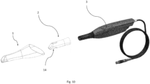
- Example 10 - A system comprising a sheath for a tip of an intraoral scanning device, shown as un-mounted
- Fig. 10 shows another example system of an intraoral scanning device (3), comprising: the sheath (1) as shown in Fig. 7 , a tip (2) for the scanning device (3) as shown in Fig.9 , wherein the tip (2) is replaceably mountable on the intraoral scanning device (3).
- the tip (2) comprises an aperture (14) on an optical axis such that light is allowed to exit and to enter the scanning device (3) via the optical axis (10).
- the sheath (1), the tip (2) and the scanning device (3) are shown as unmounted from each other.
- Example 11 A one piece semi-flexible molted sheath as shown from a perspective view
- Fig. 11 shows another example of the sheath (1) according to the invention.
- Fig. 11 shows a semi-flexible injection molded sheath (1) for a tip (2) of a scanning device (3), comprising: a semi-flexible body (4) comprising a distal end (6) and a proximal end (7).
- the proximal end (7) comprises an opening (8) that is dimensioned with respect to at least the tip (2) of the scanning device (3), such that the body (4) is able to replaceably fit around at least a part of the tip (2) of the scanning device (3).
- the body (4) is molted in a resin composition which is characterized by a high refractive index, a low birefringence, high heat resistance and transparency.
- the part of the body (4) situated below the tip aperture (14), when mounted on the tip (2), will hence make up an optical window (9) such that the optical window (9) allows for light to exit and to enter the scanning device (3) via an optical axis (10) inside the tip (2) without substantially altering the polarization of said light.
- the optical window (9) composed by the body (4) is situated such that the optical window (9) comprises a surface normal (11) that deviates from the optical axis (10), whereby internal reflections of the light that exits via the tip (2) is guided away from the optical axis (10).
- the optical window may contain a hydrophilic coating, such that no fogging of the window will occur when exposed to a humid environment such as the oral cavity
Landscapes
- Health & Medical Sciences (AREA)
- Life Sciences & Earth Sciences (AREA)
- Surgery (AREA)
- Veterinary Medicine (AREA)
- Public Health (AREA)
- General Health & Medical Sciences (AREA)
- Animal Behavior & Ethology (AREA)
- Engineering & Computer Science (AREA)
- Physics & Mathematics (AREA)
- Optics & Photonics (AREA)
- Nuclear Medicine, Radiotherapy & Molecular Imaging (AREA)
- Biophysics (AREA)
- Biomedical Technology (AREA)
- Heart & Thoracic Surgery (AREA)
- Medical Informatics (AREA)
- Molecular Biology (AREA)
- Pathology (AREA)
- Radiology & Medical Imaging (AREA)
- Oral & Maxillofacial Surgery (AREA)
- Dentistry (AREA)
- Epidemiology (AREA)
- Manufacturing & Machinery (AREA)
- Endoscopes (AREA)
- Microscoopes, Condenser (AREA)
- Facsimile Scanning Arrangements (AREA)
- Cash Registers Or Receiving Machines (AREA)
Claims (15)
- Gaine configurée pour être montée de façon remplaçable sur au moins une partie d'un embout d'un dispositif de balayage intrabuccal, étant ainsi configurée pour être utilisée en combinaison avec le dispositif de balayage intrabuccal pour balayer une cavité intrabuccale, la gaine comprenant :- un corps creux comprenant une extrémité distale de gaine, une extrémité proximale de gaine et une paroi latérale de gaine située entre l'extrémité distale de gaine et l'extrémité proximale de gaine, dans laquelle l'extrémité proximale de gaine forme une ouverture de gaine qui est dimensionnée par rapport à au moins la partie de l'embout ; et- une fenêtre optique montée sur ou située dans la paroi côté gaine près de l'extrémité distale de gaine de telle sorte que lorsque la gaine est montée de façon remplaçable sur au moins la partie de l'embout par l'intermédiaire de l'ouverture de gaine, la fenêtre optique couvre au moins une partie d'une ouverture optique de l'embout, dans laquelle la fenêtre optique présente une épaisseur qui n'est pas supérieure à 400 microns et une biréfringence de 100 000 nm/cm ou moins.
- Gaine selon la revendication 1, dans laquelle la fenêtre optique présente une biréfringence de 10 000 nm/cm ou moins.
- Gaine selon l'une quelconque des revendications précédentes, dans laquelle la fenêtre optique présente une biréfringence de 1000 nm/cm ou moins.
- Gaine selon l'une quelconque des revendications précédentes, dans laquelle la fenêtre optique est constituée d'un matériau ayant deux indices de réfraction, no et ne, le long de deux directions optiques, dans laquelle no et ne diffèrent l'un de l'autre de moins de 15 %.
- Gaine selon la revendication 4, dans laquelle no et ne diffèrent l'un de l'autre de moins de 1 %.
- Gaine selon l'une quelconque des revendications précédentes, dans laquelle la fenêtre optique est supérieure à 10 mm par 10 mm.
- Gaine selon l'une quelconque des revendications précédentes, dans laquelle la fenêtre optique présente une épaisseur supérieure à 600 microns
- Gaine selon l'une quelconque des revendications précédentes, dans laquelle la fenêtre optique est constituée de poly(méthyl méthacrylate) (PMMA).
- Gaine selon l'une quelconque des revendications précédentes, dans laquelle la fenêtre optique est moulée par injection.
- Gaine selon l'une quelconque des revendications précédentes, dans laquelle la fenêtre optique est une partie intégrée du corps creux.
- Gaine selon l'une quelconque des revendications précédentes, dans laquelle la fenêtre optique comprend une surface hydrophile.
- Gaine selon l'une quelconque des revendications précédentes, dans laquelle le corps creux est rigide.
- Gaine selon l'une quelconque des revendications précédentes, dans laquelle le corps creux est constitué d'un ou plusieurs polymères.
- Gaine selon l'une quelconque des revendications précédentes, dans laquelle la gaine est adaptée à un usage unique.
- Système comprenant :- un dispositif de balayage intrabuccal comprenant un embout ; et- une gaine selon l'une quelconque des revendications 1-14.
Applications Claiming Priority (3)
| Application Number | Priority Date | Filing Date | Title |
|---|---|---|---|
| EP18194075 | 2018-09-12 | ||
| PCT/EP2019/073972 WO2020053136A1 (fr) | 2018-09-12 | 2019-09-09 | Gaine pour un embout d'un dispositif de balayage et son système |
| EP19762824.1A EP3849395B1 (fr) | 2018-09-12 | 2019-09-09 | Gaine pour une pointe d'un dispositif de balayage et système associé |
Related Parent Applications (3)
| Application Number | Title | Priority Date | Filing Date |
|---|---|---|---|
| PCT/EP2019/073972 Previously-Filed-Application WO2020053136A1 (fr) | 2018-09-12 | 2019-09-09 | Gaine pour un embout d'un dispositif de balayage et son système |
| EP19762824.1A Division-Into EP3849395B1 (fr) | 2018-09-12 | 2019-09-09 | Gaine pour une pointe d'un dispositif de balayage et système associé |
| EP19762824.1A Division EP3849395B1 (fr) | 2018-09-12 | 2019-09-09 | Gaine pour une pointe d'un dispositif de balayage et système associé |
Publications (3)
| Publication Number | Publication Date |
|---|---|
| EP4268765A2 EP4268765A2 (fr) | 2023-11-01 |
| EP4268765A3 EP4268765A3 (fr) | 2023-12-27 |
| EP4268765B1 true EP4268765B1 (fr) | 2025-01-22 |
Family
ID=63579086
Family Applications (2)
| Application Number | Title | Priority Date | Filing Date |
|---|---|---|---|
| EP23189714.1A Active EP4268765B1 (fr) | 2018-09-12 | 2019-09-09 | Gaine pour une pointe d'un dispositif de balayage et système associé |
| EP19762824.1A Active EP3849395B1 (fr) | 2018-09-12 | 2019-09-09 | Gaine pour une pointe d'un dispositif de balayage et système associé |
Family Applications After (1)
| Application Number | Title | Priority Date | Filing Date |
|---|---|---|---|
| EP19762824.1A Active EP3849395B1 (fr) | 2018-09-12 | 2019-09-09 | Gaine pour une pointe d'un dispositif de balayage et système associé |
Country Status (8)
| Country | Link |
|---|---|
| US (2) | US12303104B2 (fr) |
| EP (2) | EP4268765B1 (fr) |
| JP (1) | JP2022500131A (fr) |
| KR (1) | KR102852540B1 (fr) |
| CN (1) | CN113015477B (fr) |
| BR (1) | BR112021004426A2 (fr) |
| ES (2) | ES2967236T3 (fr) |
| WO (1) | WO2020053136A1 (fr) |
Families Citing this family (13)
| Publication number | Priority date | Publication date | Assignee | Title |
|---|---|---|---|---|
| WO2020053136A1 (fr) | 2018-09-12 | 2020-03-19 | 3Shape A/S | Gaine pour un embout d'un dispositif de balayage et son système |
| JP2022521970A (ja) * | 2019-02-27 | 2022-04-13 | 3シェイプ アー/エス | 交換可能な走査先端部を有する走査装置 |
| AU2020254822B2 (en) * | 2019-04-05 | 2025-05-01 | Align Technology, Inc. | Intraoral scanner sleeve authentication and identification |
| WO2022036400A1 (fr) * | 2020-08-21 | 2022-02-24 | Optiscan Pty Ltd | Sonde optique et système de traitement |
| WO2022154622A1 (fr) * | 2021-01-18 | 2022-07-21 | 주식회사 메디트 | Scanner tridimensionnel |
| EP4340773B1 (fr) * | 2021-05-18 | 2025-05-21 | Align Technology, Inc. | Manchon de scanner intrabuccal |
| USD1073069S1 (en) | 2021-05-18 | 2025-04-29 | Align Technology, Inc. | Protective sleeve for an intraoral scanner |
| CN119421671A (zh) * | 2022-07-01 | 2025-02-11 | 3 形状股份有限公司 | 口内扫描仪系统 |
| WO2024002856A1 (fr) * | 2022-07-01 | 2024-01-04 | 3Shape A/S | Scanner intra-buccal à boîtier hygiénique |
| USD1051387S1 (en) * | 2022-12-08 | 2024-11-12 | 3Shape A/S | Scanner with a tip |
| USD1048401S1 (en) * | 2022-12-08 | 2024-10-22 | 3Shape A/S | Scanner tip |
| KR20260020965A (ko) * | 2023-06-09 | 2026-02-12 | 쓰리세이프 에이/에스 | 핸드헬드 구강내 스캐너용 탈착가능한 슬리브 및 핸드헬드 구강내 스캐너용 탈착가능한 슬리브를 제조하기 위한 방법 |
| EP4534002B1 (fr) | 2023-10-04 | 2026-04-01 | 3Shape A/S | Système de scanner intraoral et procédé d'élimination d'artefacts provenant de réflexions |
Family Cites Families (25)
| Publication number | Priority date | Publication date | Assignee | Title |
|---|---|---|---|---|
| US20030107652A1 (en) * | 1992-09-11 | 2003-06-12 | Williams Ronald R. | Dental video camera |
| JP3695781B2 (ja) | 1994-11-18 | 2005-09-14 | オリンパス株式会社 | 保護カバー付き内視鏡 |
| JPH11192207A (ja) | 1997-11-07 | 1999-07-21 | Matsushita Electric Ind Co Ltd | ビデオスコープおよび携帯収納ケース |
| US6549794B1 (en) * | 1999-09-24 | 2003-04-15 | Cytometrics, Llc | Single use disposable protective cap |
| JP2001212161A (ja) | 2000-01-31 | 2001-08-07 | Matsushita Electric Ind Co Ltd | ビデオスコープ付き口腔洗浄器 |
| AU2002364069A1 (en) * | 2001-12-18 | 2003-06-30 | Advanced Cardiovascular Systems, Inc. | Optical guidewire having windows or apertures |
| JP2005168770A (ja) * | 2003-12-10 | 2005-06-30 | Olympus Corp | 内視鏡 |
| US7796243B2 (en) | 2004-06-09 | 2010-09-14 | National Research Council Of Canada | Detection and monitoring of changes in mineralized tissues or calcified deposits by optical coherence tomography and Raman spectroscopy |
| US20070260231A1 (en) | 2005-04-21 | 2007-11-08 | Ondine International, Ltd. | Optical probe for delivery of light |
| US20090147373A1 (en) * | 2007-10-19 | 2009-06-11 | University Of Central Florida Research Foundation, Inc. | Dynamic Focus Optical Probes |
| JP4803402B2 (ja) | 2008-07-07 | 2011-10-26 | 株式会社モリタ東京製作所 | 歯科光診断装置用プローブ |
| US20100036260A1 (en) | 2008-08-07 | 2010-02-11 | Remicalm Llc | Oral cancer screening device |
| EP2337519A4 (fr) * | 2008-09-24 | 2012-04-18 | Dentsply Int Inc | Dispositif d'imagerie pour instruments dentaires et procédés de visualisation intra-orale |
| WO2011140664A2 (fr) | 2010-05-13 | 2011-11-17 | Quantum Dental Technologies Inc. | Embout à main à système optique intégré pour mesures de radiométrie photothermique et de luminescence |
| US20120010468A1 (en) | 2010-07-06 | 2012-01-12 | Adel Afridi | System of disposable contoured sleeves for flexible endoscopes |
| CN102228377A (zh) * | 2011-07-07 | 2011-11-02 | 傅强 | 用于内窥镜的一次性灭菌透视护套 |
| CN104780822B (zh) | 2012-07-19 | 2017-06-23 | 独立行政法人国立长寿医疗研究中心 | 牙菌斑、牙龈和牙槽骨的测量和显示方法及装置 |
| US20140272766A1 (en) | 2013-03-14 | 2014-09-18 | Ormco Corporation | Head mounted display for an intra-oral imaging system |
| KR102227160B1 (ko) | 2013-09-30 | 2021-03-12 | 디아이씨 가부시끼가이샤 | 광학 재료용 수지 조성물, 광학 필름 및 액정 표시 장치 |
| US20150230882A1 (en) * | 2014-02-19 | 2015-08-20 | Tidi Products, Llc | Dental Curing Light Sleeve |
| US9848773B2 (en) | 2015-01-26 | 2017-12-26 | Visunex Medical Systems Co. Ltd. | Disposable cap for an eye imaging apparatus and related methods |
| US20160367120A1 (en) * | 2015-06-19 | 2016-12-22 | Children's Medical Center Corporation | Optically Guided Surgical Devices |
| US10842352B2 (en) | 2016-04-11 | 2020-11-24 | Canon U.S.A., Inc. | Endoscope sheath with integral imaging window |
| US10792127B2 (en) | 2017-01-24 | 2020-10-06 | Align Technology, Inc. | Adaptive orthodontic treatment |
| WO2020053136A1 (fr) | 2018-09-12 | 2020-03-19 | 3Shape A/S | Gaine pour un embout d'un dispositif de balayage et son système |
-
2019
- 2019-09-09 WO PCT/EP2019/073972 patent/WO2020053136A1/fr not_active Ceased
- 2019-09-09 KR KR1020217010531A patent/KR102852540B1/ko active Active
- 2019-09-09 ES ES19762824T patent/ES2967236T3/es active Active
- 2019-09-09 BR BR112021004426-4A patent/BR112021004426A2/pt not_active IP Right Cessation
- 2019-09-09 JP JP2021513428A patent/JP2022500131A/ja active Pending
- 2019-09-09 EP EP23189714.1A patent/EP4268765B1/fr active Active
- 2019-09-09 US US17/275,441 patent/US12303104B2/en active Active
- 2019-09-09 ES ES23189714T patent/ES3014085T3/es active Active
- 2019-09-09 EP EP19762824.1A patent/EP3849395B1/fr active Active
- 2019-09-09 CN CN201980074209.3A patent/CN113015477B/zh active Active
-
2023
- 2023-08-18 US US18/451,888 patent/US20230389778A1/en active Pending
Also Published As
| Publication number | Publication date |
|---|---|
| ES3014085T3 (en) | 2025-04-16 |
| JP2022500131A (ja) | 2022-01-04 |
| KR102852540B1 (ko) | 2025-08-28 |
| EP3849395B1 (fr) | 2023-11-01 |
| US12303104B2 (en) | 2025-05-20 |
| CN113015477A (zh) | 2021-06-22 |
| ES2967236T3 (es) | 2024-04-29 |
| CN113015477B (zh) | 2025-02-07 |
| US20220079426A1 (en) | 2022-03-17 |
| BR112021004426A2 (pt) | 2021-05-25 |
| KR20210057779A (ko) | 2021-05-21 |
| US20230389778A1 (en) | 2023-12-07 |
| EP3849395A1 (fr) | 2021-07-21 |
| EP4268765A2 (fr) | 2023-11-01 |
| EP4268765A3 (fr) | 2023-12-27 |
| WO2020053136A1 (fr) | 2020-03-19 |
Similar Documents
| Publication | Publication Date | Title |
|---|---|---|
| US20230389778A1 (en) | Sheath for a tip of a scanning device and system thereof | |
| EP3207852B1 (fr) | Composant d'extrémité distale de résine pour endoscope | |
| CN102316783B (zh) | 内窥镜 | |
| JP2716265B2 (ja) | 無菌スリーブを備えた内視鏡 | |
| KR102889194B1 (ko) | 광학적 이미지 시각화기를 위한 내시경 | |
| BRPI0615651A2 (pt) | tampa descartável para endoscópio | |
| EP3613327A1 (fr) | Partie de pointe pour dispositif de vision | |
| JP2009532153A (ja) | 内視鏡用保護体及びこれに対応する内視鏡 | |
| US20180325368A1 (en) | Anti-fog film for an endoscope | |
| CN111712174A (zh) | 用于刚性内窥镜的护套组合件 | |
| CN210055945U (zh) | 一种带有一次性护套管的内窥镜 | |
| KR20190106355A (ko) | 이미징 프로브 및 의료용 내시경 | |
| JP5988807B2 (ja) | 内視鏡用シース、内視鏡システム | |
| JP6865410B2 (ja) | 視野確保装置、及び内視鏡システム | |
| US20180310808A1 (en) | Sterile adapter | |
| JP6671967B2 (ja) | 内視鏡 | |
| JP4135877B2 (ja) | 内視鏡の先端部 | |
| JP2586248Y2 (ja) | 内視鏡カバー方式の内視鏡装置 | |
| JP4172959B2 (ja) | 内視鏡の先端部 | |
| CN209186634U (zh) | 宽视场内窥镜 | |
| JP4297481B2 (ja) | 内視鏡の先端部 | |
| EP4094664A1 (fr) | Un endoscope | |
| JP2004049265A (ja) | 内視鏡の先端部 | |
| JP2004267255A (ja) | 外套シース付内視鏡の先端部 | |
| CN118542633A (zh) | 一次性使用内窥镜导管 |
Legal Events
| Date | Code | Title | Description |
|---|---|---|---|
| PUAI | Public reference made under article 153(3) epc to a published international application that has entered the european phase |
Free format text: ORIGINAL CODE: 0009012 |
|
| STAA | Information on the status of an ep patent application or granted ep patent |
Free format text: STATUS: THE APPLICATION HAS BEEN PUBLISHED |
|
| AC | Divisional application: reference to earlier application |
Ref document number: 3849395 Country of ref document: EP Kind code of ref document: P |
|
| AK | Designated contracting states |
Kind code of ref document: A2 Designated state(s): AL AT BE BG CH CY CZ DE DK EE ES FI FR GB GR HR HU IE IS IT LI LT LU LV MC MK MT NL NO PL PT RO RS SE SI SK SM TR |
|
| REG | Reference to a national code |
Ref country code: DE Ref legal event code: R079 Free format text: PREVIOUS MAIN CLASS: A61C0009000000 Ipc: A61B0001240000 Ref document number: 602019065312 Country of ref document: DE |
|
| PUAL | Search report despatched |
Free format text: ORIGINAL CODE: 0009013 |
|
| AK | Designated contracting states |
Kind code of ref document: A3 Designated state(s): AL AT BE BG CH CY CZ DE DK EE ES FI FR GB GR HR HU IE IS IT LI LT LU LV MC MK MT NL NO PL PT RO RS SE SI SK SM TR |
|
| RIC1 | Information provided on ipc code assigned before grant |
Ipc: A61C 9/00 20060101ALI20231122BHEP Ipc: A61C 1/16 20060101ALI20231122BHEP Ipc: A61B 1/227 20060101ALI20231122BHEP Ipc: A61B 1/00 20060101ALI20231122BHEP Ipc: A61B 1/24 20060101AFI20231122BHEP |
|
| STAA | Information on the status of an ep patent application or granted ep patent |
Free format text: STATUS: REQUEST FOR EXAMINATION WAS MADE |
|
| 17P | Request for examination filed |
Effective date: 20240621 |
|
| RBV | Designated contracting states (corrected) |
Designated state(s): AL AT BE BG CH CY CZ DE DK EE ES FI FR GB GR HR HU IE IS IT LI LT LU LV MC MK MT NL NO PL PT RO RS SE SI SK SM TR |
|
| GRAP | Despatch of communication of intention to grant a patent |
Free format text: ORIGINAL CODE: EPIDOSNIGR1 |
|
| STAA | Information on the status of an ep patent application or granted ep patent |
Free format text: STATUS: GRANT OF PATENT IS INTENDED |
|
| INTG | Intention to grant announced |
Effective date: 20240808 |
|
| GRAS | Grant fee paid |
Free format text: ORIGINAL CODE: EPIDOSNIGR3 |
|
| GRAA | (expected) grant |
Free format text: ORIGINAL CODE: 0009210 |
|
| STAA | Information on the status of an ep patent application or granted ep patent |
Free format text: STATUS: THE PATENT HAS BEEN GRANTED |
|
| AC | Divisional application: reference to earlier application |
Ref document number: 3849395 Country of ref document: EP Kind code of ref document: P |
|
| AK | Designated contracting states |
Kind code of ref document: B1 Designated state(s): AL AT BE BG CH CY CZ DE DK EE ES FI FR GB GR HR HU IE IS IT LI LT LU LV MC MK MT NL NO PL PT RO RS SE SI SK SM TR |
|
| REG | Reference to a national code |
Ref country code: GB Ref legal event code: FG4D |
|
| REG | Reference to a national code |
Ref country code: CH Ref legal event code: EP |
|
| REG | Reference to a national code |
Ref country code: IE Ref legal event code: FG4D |
|
| REG | Reference to a national code |
Ref country code: DE Ref legal event code: R096 Ref document number: 602019065312 Country of ref document: DE |
|
| P01 | Opt-out of the competence of the unified patent court (upc) registered |
Free format text: CASE NUMBER: APP_3292/2025 Effective date: 20250121 |
|
| REG | Reference to a national code |
Ref country code: ES Ref legal event code: FG2A Ref document number: 3014085 Country of ref document: ES Kind code of ref document: T3 Effective date: 20250416 |
|
| REG | Reference to a national code |
Ref country code: NL Ref legal event code: MP Effective date: 20250122 |
|
| PG25 | Lapsed in a contracting state [announced via postgrant information from national office to epo] |
Ref country code: NL Free format text: LAPSE BECAUSE OF FAILURE TO SUBMIT A TRANSLATION OF THE DESCRIPTION OR TO PAY THE FEE WITHIN THE PRESCRIBED TIME-LIMIT Effective date: 20250122 |
|
| PG25 | Lapsed in a contracting state [announced via postgrant information from national office to epo] |
Ref country code: RS Free format text: LAPSE BECAUSE OF FAILURE TO SUBMIT A TRANSLATION OF THE DESCRIPTION OR TO PAY THE FEE WITHIN THE PRESCRIBED TIME-LIMIT Effective date: 20250422 |
|
| PG25 | Lapsed in a contracting state [announced via postgrant information from national office to epo] |
Ref country code: FI Free format text: LAPSE BECAUSE OF FAILURE TO SUBMIT A TRANSLATION OF THE DESCRIPTION OR TO PAY THE FEE WITHIN THE PRESCRIBED TIME-LIMIT Effective date: 20250122 |
|
| PG25 | Lapsed in a contracting state [announced via postgrant information from national office to epo] |
Ref country code: PL Free format text: LAPSE BECAUSE OF FAILURE TO SUBMIT A TRANSLATION OF THE DESCRIPTION OR TO PAY THE FEE WITHIN THE PRESCRIBED TIME-LIMIT Effective date: 20250122 |
|
| REG | Reference to a national code |
Ref country code: LT Ref legal event code: MG9D |
|
| PG25 | Lapsed in a contracting state [announced via postgrant information from national office to epo] |
Ref country code: IS Free format text: LAPSE BECAUSE OF FAILURE TO SUBMIT A TRANSLATION OF THE DESCRIPTION OR TO PAY THE FEE WITHIN THE PRESCRIBED TIME-LIMIT Effective date: 20250522 Ref country code: NO Free format text: LAPSE BECAUSE OF FAILURE TO SUBMIT A TRANSLATION OF THE DESCRIPTION OR TO PAY THE FEE WITHIN THE PRESCRIBED TIME-LIMIT Effective date: 20250422 |
|
| REG | Reference to a national code |
Ref country code: AT Ref legal event code: MK05 Ref document number: 1760796 Country of ref document: AT Kind code of ref document: T Effective date: 20250122 |
|
| PG25 | Lapsed in a contracting state [announced via postgrant information from national office to epo] |
Ref country code: HR Free format text: LAPSE BECAUSE OF FAILURE TO SUBMIT A TRANSLATION OF THE DESCRIPTION OR TO PAY THE FEE WITHIN THE PRESCRIBED TIME-LIMIT Effective date: 20250122 |
|
| PG25 | Lapsed in a contracting state [announced via postgrant information from national office to epo] |
Ref country code: LV Free format text: LAPSE BECAUSE OF FAILURE TO SUBMIT A TRANSLATION OF THE DESCRIPTION OR TO PAY THE FEE WITHIN THE PRESCRIBED TIME-LIMIT Effective date: 20250122 Ref country code: PT Free format text: LAPSE BECAUSE OF FAILURE TO SUBMIT A TRANSLATION OF THE DESCRIPTION OR TO PAY THE FEE WITHIN THE PRESCRIBED TIME-LIMIT Effective date: 20250522 |
|
| PG25 | Lapsed in a contracting state [announced via postgrant information from national office to epo] |
Ref country code: GR Free format text: LAPSE BECAUSE OF FAILURE TO SUBMIT A TRANSLATION OF THE DESCRIPTION OR TO PAY THE FEE WITHIN THE PRESCRIBED TIME-LIMIT Effective date: 20250423 Ref country code: BG Free format text: LAPSE BECAUSE OF FAILURE TO SUBMIT A TRANSLATION OF THE DESCRIPTION OR TO PAY THE FEE WITHIN THE PRESCRIBED TIME-LIMIT Effective date: 20250122 |
|
| PG25 | Lapsed in a contracting state [announced via postgrant information from national office to epo] |
Ref country code: AT Free format text: LAPSE BECAUSE OF FAILURE TO SUBMIT A TRANSLATION OF THE DESCRIPTION OR TO PAY THE FEE WITHIN THE PRESCRIBED TIME-LIMIT Effective date: 20250122 |
|
| PG25 | Lapsed in a contracting state [announced via postgrant information from national office to epo] |
Ref country code: SE Free format text: LAPSE BECAUSE OF FAILURE TO SUBMIT A TRANSLATION OF THE DESCRIPTION OR TO PAY THE FEE WITHIN THE PRESCRIBED TIME-LIMIT Effective date: 20250122 |
|
| PG25 | Lapsed in a contracting state [announced via postgrant information from national office to epo] |
Ref country code: SM Free format text: LAPSE BECAUSE OF FAILURE TO SUBMIT A TRANSLATION OF THE DESCRIPTION OR TO PAY THE FEE WITHIN THE PRESCRIBED TIME-LIMIT Effective date: 20250122 |
|
| PG25 | Lapsed in a contracting state [announced via postgrant information from national office to epo] |
Ref country code: DK Free format text: LAPSE BECAUSE OF FAILURE TO SUBMIT A TRANSLATION OF THE DESCRIPTION OR TO PAY THE FEE WITHIN THE PRESCRIBED TIME-LIMIT Effective date: 20250122 |
|
| PGFP | Annual fee paid to national office [announced via postgrant information from national office to epo] |
Ref country code: DE Payment date: 20250919 Year of fee payment: 7 |
|
| PGFP | Annual fee paid to national office [announced via postgrant information from national office to epo] |
Ref country code: IT Payment date: 20250923 Year of fee payment: 7 |
|
| PGFP | Annual fee paid to national office [announced via postgrant information from national office to epo] |
Ref country code: GB Payment date: 20250919 Year of fee payment: 7 |
|
| PGFP | Annual fee paid to national office [announced via postgrant information from national office to epo] |
Ref country code: FR Payment date: 20250922 Year of fee payment: 7 |
|
| PG25 | Lapsed in a contracting state [announced via postgrant information from national office to epo] |
Ref country code: EE Free format text: LAPSE BECAUSE OF FAILURE TO SUBMIT A TRANSLATION OF THE DESCRIPTION OR TO PAY THE FEE WITHIN THE PRESCRIBED TIME-LIMIT Effective date: 20250122 Ref country code: CZ Free format text: LAPSE BECAUSE OF FAILURE TO SUBMIT A TRANSLATION OF THE DESCRIPTION OR TO PAY THE FEE WITHIN THE PRESCRIBED TIME-LIMIT Effective date: 20250122 |
|
| REG | Reference to a national code |
Ref country code: DE Ref legal event code: R097 Ref document number: 602019065312 Country of ref document: DE |
|
| PG25 | Lapsed in a contracting state [announced via postgrant information from national office to epo] |
Ref country code: RO Free format text: LAPSE BECAUSE OF FAILURE TO SUBMIT A TRANSLATION OF THE DESCRIPTION OR TO PAY THE FEE WITHIN THE PRESCRIBED TIME-LIMIT Effective date: 20250122 |
|
| PG25 | Lapsed in a contracting state [announced via postgrant information from national office to epo] |
Ref country code: SK Free format text: LAPSE BECAUSE OF FAILURE TO SUBMIT A TRANSLATION OF THE DESCRIPTION OR TO PAY THE FEE WITHIN THE PRESCRIBED TIME-LIMIT Effective date: 20250122 |
|
| PLBE | No opposition filed within time limit |
Free format text: ORIGINAL CODE: 0009261 |
|
| STAA | Information on the status of an ep patent application or granted ep patent |
Free format text: STATUS: NO OPPOSITION FILED WITHIN TIME LIMIT |
|
| REG | Reference to a national code |
Ref country code: CH Ref legal event code: L10 Free format text: ST27 STATUS EVENT CODE: U-0-0-L10-L00 (AS PROVIDED BY THE NATIONAL OFFICE) Effective date: 20251203 |
|
| 26N | No opposition filed |
Effective date: 20251023 |
|
| PGFP | Annual fee paid to national office [announced via postgrant information from national office to epo] |
Ref country code: ES Payment date: 20251030 Year of fee payment: 7 |
|
| REG | Reference to a national code |
Ref country code: CH Ref legal event code: H13 Free format text: ST27 STATUS EVENT CODE: U-0-0-H10-H13 (AS PROVIDED BY THE NATIONAL OFFICE) Effective date: 20260425 |