EP4268919A1 - Dégazeur - Google Patents
Dégazeur Download PDFInfo
- Publication number
- EP4268919A1 EP4268919A1 EP21910563.2A EP21910563A EP4268919A1 EP 4268919 A1 EP4268919 A1 EP 4268919A1 EP 21910563 A EP21910563 A EP 21910563A EP 4268919 A1 EP4268919 A1 EP 4268919A1
- Authority
- EP
- European Patent Office
- Prior art keywords
- degassing
- piping
- reduced
- atmospheric release
- discharge device
- Prior art date
- Legal status (The legal status is an assumption and is not a legal conclusion. Google has not performed a legal analysis and makes no representation as to the accuracy of the status listed.)
- Pending
Links
Images


Classifications
-
- B—PERFORMING OPERATIONS; TRANSPORTING
- B01—PHYSICAL OR CHEMICAL PROCESSES OR APPARATUS IN GENERAL
- B01D—SEPARATION
- B01D19/00—Degasification of liquids
- B01D19/0031—Degasification of liquids by filtration
-
- B—PERFORMING OPERATIONS; TRANSPORTING
- B01—PHYSICAL OR CHEMICAL PROCESSES OR APPARATUS IN GENERAL
- B01D—SEPARATION
- B01D19/00—Degasification of liquids
- B01D19/0063—Regulation, control including valves and floats
-
- B—PERFORMING OPERATIONS; TRANSPORTING
- B01—PHYSICAL OR CHEMICAL PROCESSES OR APPARATUS IN GENERAL
- B01D—SEPARATION
- B01D61/00—Processes of separation using semi-permeable membranes, e.g. dialysis, osmosis or ultrafiltration; Apparatus, accessories or auxiliary operations specially adapted therefor
-
- B—PERFORMING OPERATIONS; TRANSPORTING
- B01—PHYSICAL OR CHEMICAL PROCESSES OR APPARATUS IN GENERAL
- B01D—SEPARATION
- B01D63/00—Apparatus in general for separation processes using semi-permeable membranes
- B01D63/02—Hollow fibre modules
- B01D63/024—Hollow fibre modules with a single potted end
- B01D63/0241—Hollow fibre modules with a single potted end being U-shaped
-
- B—PERFORMING OPERATIONS; TRANSPORTING
- B01—PHYSICAL OR CHEMICAL PROCESSES OR APPARATUS IN GENERAL
- B01D—SEPARATION
- B01D63/00—Apparatus in general for separation processes using semi-permeable membranes
- B01D63/02—Hollow fibre modules
- B01D63/04—Hollow fibre modules comprising multiple hollow fibre assemblies
- B01D63/046—Hollow fibre modules comprising multiple hollow fibre assemblies in separate housings
-
- B—PERFORMING OPERATIONS; TRANSPORTING
- B01—PHYSICAL OR CHEMICAL PROCESSES OR APPARATUS IN GENERAL
- B01D—SEPARATION
- B01D63/00—Apparatus in general for separation processes using semi-permeable membranes
- B01D63/06—Tubular membrane modules
- B01D63/069—Tubular membrane modules comprising a bundle of tubular membranes
-
- B—PERFORMING OPERATIONS; TRANSPORTING
- B01—PHYSICAL OR CHEMICAL PROCESSES OR APPARATUS IN GENERAL
- B01D—SEPARATION
- B01D2313/00—Details relating to membrane modules or apparatus
- B01D2313/10—Specific supply elements
-
- B—PERFORMING OPERATIONS; TRANSPORTING
- B01—PHYSICAL OR CHEMICAL PROCESSES OR APPARATUS IN GENERAL
- B01D—SEPARATION
- B01D2313/00—Details relating to membrane modules or apparatus
- B01D2313/12—Specific discharge elements
-
- B—PERFORMING OPERATIONS; TRANSPORTING
- B01—PHYSICAL OR CHEMICAL PROCESSES OR APPARATUS IN GENERAL
- B01D—SEPARATION
- B01D2313/00—Details relating to membrane modules or apparatus
- B01D2313/13—Specific connectors
-
- B—PERFORMING OPERATIONS; TRANSPORTING
- B01—PHYSICAL OR CHEMICAL PROCESSES OR APPARATUS IN GENERAL
- B01D—SEPARATION
- B01D69/00—Semi-permeable membranes for separation processes or apparatus characterised by their form, structure or properties; Manufacturing processes specially adapted therefor
- B01D69/04—Tubular membranes
Definitions
- the present invention relates to a degassing apparatus, and particularly to a degassing apparatus with a plurality of degassing modules.
- PTL 1 and PTL 2 disclose a degassing apparatus used in a liquid chromatography device and the like.
- the degassing apparatus described in PTL 1 has a valve between a reduced-pressure space in a degassing module and a vacuum pump and is configured to gradually return the reduced-pressure space in the degassing module to the atmospheric pressure after the device stops operation.
- a valve between a reduced-pressure space in a degassing module and a vacuum pump and is configured to gradually return the reduced-pressure space in the degassing module to the atmospheric pressure after the device stops operation.
- the degree of depressurization varies among the degassing modules for a longer time. This tends to cause cross-contamination in which vaporized gas is mixed in another degassing module.
- individual valves are installed in the degassing modules to eliminate such a time difference, the device configuration becomes more complex or the manufacturing cost increases due to the increased number of components.
- An object according to an aspect of the present invention is to provide a degassing apparatus that can prevent cross-contamination.
- a degassing apparatus includes: a first degassing module and a second degassing module, each having a gas permeable membrane to separate a fluid circulation space and a reduced-pressure space from each other; vacuum piping having discharge piping sections continuous to respective discharge ports of the first degassing module and the second degassing module, and a discharge assembly section configured to assemble the discharge piping sections, the vacuum piping being communicatively connected to the respective reduced-pressure spaces of the first degassing module and the second degassing module; a discharge device communicatively connected to the vacuum piping and configured to discharge gas in the respective reduced-pressure spaces to outside through the vacuum piping; atmospheric release piping having release piping sections continuous to respective release ports of the first degassing module and the second degassing module, and a release assembly section configured to assemble the release piping sections, the atmospheric release piping being communicatively connected to the respective reduced-pressure spaces of the first degassing module and the second degassing module;
- the control unit performs control to close the atmospheric release valve to perform a process of discharging gas in the respective reduced-pressure spaces by the discharge device when a degassing process is being performed in at least one of the first degassing module and the second degassing module, and performs control to open the atmospheric release valve to open the respective reduced-pressure spaces to the atmosphere at once after the degassing process is finished.
- the vacuum piping for discharging the atmosphere from the reduced-pressure spaces of the degassing modules and the atmospheric release piping for opening the reduced-pressure spaces to the atmosphere are provided separately, and after the degassing process in the degassing module is finished, the atmospheric release valve is opened to open the reduced-pressure spaces to the atmosphere at once.
- the above degassing apparatus may further include a detector for detecting the degree of depressurization in the reduced-pressure space, and the vacuum piping may further have a detection piping section communicatively connected to the detector.
- the detector has a diaphragm for detecting the degree of depressurization, and the detector is installed such that a detection surface of the diaphragm faces downward.
- Vaporized gas may sometimes enter the vacuum piping, but the detection surface of the diaphragm faces downward to prevent gas intrusion from the vacuum piping from remaining attached to the detection surface.
- the gas is a corrosive medium gas
- such a configuration can be employed to suppress deterioration of the detection surface and enable stable detection of the degree of depressurization over a long period of time.
- the above degassing apparatus further includes a bottom plate defining a bottom of the degassing apparatus, and the discharge device is disposed on the bottom plate with anti-vibration means interposed therebetween.
- the discharge device may sometimes generate vibrations with the pump mechanism or the like and such vibrations may damage the gas permeable membranes (e.g., hollow fiber membranes) that constitute the degassing modules in the degassing apparatus.
- the vibrations may also cause microbubbles in a fluid flowing in the degassing modules to affect the test.
- the provision of such anti-vibration means can suppress transmission of vibrations of the discharge device to other components and suppress the damage to the gas permeable membranes and the growth of microbubbles in the test fluid.
- the discharge device may be supported on the bottom plate by a plurality of legs and positioned at a predetermined height from a surface of the bottom plate. This configuration can further suppress transmission of vibrations from the discharge device to other components and, in addition, can prevent erosion of the discharge device by a fluid to be degassed in the degassing apparatus even if the fluid leaks from the degassing modules. Even if such leakage occurs, liquid waste disposal can be easily performed.
- the anti-vibration means may be provided between a plurality of legs and the discharge device.
- the above degassing apparatus further includes a bottom plate defining a bottom of the degassing apparatus, and at least one of the control unit and the atmospheric release valve is disposed at a predetermined height from a surface of the bottom plate.
- This configuration can prevent erosion of the control unit and the atmospheric release valve by a fluid to be degassed in the degassing apparatus even if the fluid leaks from the degassing modules. Even if such leakage occurs, liquid waste disposal can be easily performed.
- At least a portion of at least one of the vacuum piping and the atmospheric release piping is formed of a resin tube, and the resin tube has a rubber hardness in a range of 70 ⁇ 30 degrees, and the resin tube has an oxygen permeability of 6000 cc(STP)cm/cm 2 /sec/cmHg ⁇ 10 -10 or less.
- This configuration can prevent erosion of the piping by vaporized gas (chemical resistance), makes it easier to arrange the piping (flexibility), and can easily increase or stabilize the degree of depressurization by the discharge device (gas permeability).
- the first degassing module may have a housing having an opening and accommodating the gas permeable membrane in a tubular shape, a lid configured to hermetically seal the opening and allow the gas permeable membrane in a tubular shape to penetrate from inside toward outside of the housing, and a connector portion connecting and fixing the gas permeable membrane in a tubular shape to the lid while maintaining airtightness of the reduced-pressure space in a region where the gas permeable membrane penetrates.
- the connector portion may include a support member disposed inside the gas permeable membrane in a tubular shape to support the gas permeable membrane in a tubular shape from the inside when connected and fixed to the lid.
- This configuration can prevent membrane breakage at the fixing and connection portion of the degassing module.
- the gas permeable membrane is a tubular hollow fiber membrane, membrane breakage is likely to occur during transportation or due to vibrations, but this configuration can prevent membrane breakage.
- the reduced-pressure space separated by the gas permeable membrane can be closed more reliably, so that the depressurization by the discharge device can be stabilized more.
- the atmospheric release piping is disposed above the vacuum piping.
- the above degassing apparatus may further include a regulating valve disposed between the degassing module and the discharge device to regulate the degree of depressurization in the reduced-pressure space.
- the control unit may perform control to close the regulating valve and stop operation of the discharge device when the degree of depressurization in the reduced-pressure space is within a predetermined range. With this configuration, the operation of the discharge device can be stopped as necessary to further suppress the vibration-induced damage and the growth of microbubbles.
- control unit may perform control to open the atmospheric release valve to open the respective reduced-pressure spaces to atmosphere at once while gas discharge operation by the discharge device continues for a predetermined time. With this control, the reduced-pressure spaces can be smoothly opened to the atmosphere by the atmospheric release valve.
- cross-contamination can be prevented.
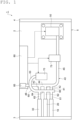
- Fig. 1 is a schematic plan view of a degassing apparatus according to an embodiment.
- Fig. 2 is a schematic side view of the degassing apparatus illustrated in Fig. 1 .
- a degassing apparatus 1 includes a housing 5 having a bottom plate 2, a front plate 3, and a rear plate 4, degassing modules 10, 20, and 30 (first and second degassing modules), vacuum piping 40, a discharge device 50, atmospheric release piping 60, an atmospheric release valve 70, a regulating valve 75, and a control unit 80.
- the degassing apparatus 1 is, for example, a degassing apparatus for liquid chromatography and performs a degassing process on a fluid to be tested in liquid chromatography.
- the degassing apparatus 1 may be used for gas chromatography, biochemical analyzers, inkjet filling devices, and the like, as a matter of course.
- the degassing modules 10, 20, and 30 have a configuration, for example, illustrated in Fig. 3.
- Fig. 3 is a schematic cross-sectional view of an example of the degassing module installed in the degassing apparatus illustrated in Fig. 1 .
- Fig. 4 is an enlarged cross-sectional view of a section around a connector portion of the degassing module illustrated in Fig. 3.
- Fig. 3 illustrates a configuration of the degassing module 10 as an example, and the other degassing modules 20 and 30 have a similar configuration. As illustrated in Fig. 3 and Fig.
- the degassing module 10 has a tube unit 12 with a plurality of tubes 11 bundled at both ends, each tube 11 defining a fluid circulation space S1 in the inside, a housing 13 that accommodates the tube unit 12, a lid 14 that hermetically seals an opening 13a of the housing 13, connector portions 15 and 16 that connect and fix the tube unit 12 penetrating through the lid 14, and a discharge port 17 and a release port 18 communicatively connected to a reduced-pressure space S2.
- the tube unit 12 which is gas permeable membranes divides the inside of the housing 13 into the fluid circulation space S1 which is an interior space of each of the tubes 11 of the tube unit 12 and the reduced-pressure space S2 which is a space outside the tube unit 12.
- the fluid circulation space S1 is a region where a liquid is supplied, and the liquid introduced from an inlet port 12a of the tube unit 12 is supplied to a discharge port 12b.
- the reduced-pressure space S2 is a region where the internal atmosphere is sucked.
- a liquid is supplied to the fluid circulation space S1 which is the interior space of each of the tubes 11, and a gas is sucked from the reduced-pressure space S2 outside the tubes 11, whereby the liquid supplied to the tube unit 12 is degassed.
- Each of the tubes 11 that constitute the tube unit 12 is a tubular membrane that allows a gas to pass through but does not allow a liquid to pass through (see Fig. 4 ).
- the material, membrane shape, membrane form, and the like of the tube 11 are not limited.
- the material of the tube 11 include fluororesins such as polytetrafluoroethylene (PTFE), tetrafluoroethylene-perfluoroalkyl vinyl ether copolymer (PFA), tetrafluoroethylene-hexafluoropropylene copolymer (FEP), tetrafluoroethylene-ethylene copolymer (ethylene copolymer) (ETFE), polychlorotrifluoroethylene (PCTFE), amorphous fluoropolymer (AF), and polyvinylidene fluoride (PVDF), polypropylene (PP), polymethylpentene (PMP), silicone, polyimide, and polyamide.
- degassing apparatus 1 three degassing modules 10, 20, and 30 in such a manner are arranged, but two degassing modules may be arranged, or four or more degassing modules may be arranged.
- the vacuum piping 40 is a member communicatively connected to the respective reduced-pressure spaces S2 of the degassing modules 10, 20, and 30 to connect the reduced-pressure spaces S2 to the discharge device 50.
- the vacuum piping 40 has discharge piping sections 41 to 43 continuous to the respective discharge ports 17 of the degassing modules 10, 20, and 30, a discharge assembly section 44 for assembling the discharge piping sections 41 to 43, piping 45 connecting the discharge assembly section 44 to the discharge device, and a detection piping section 46 communicatively connecting the discharge assembly section 44 to the detector 85.
- the detector 85 is a barometric pressure sensor that detects the degree of depressurization in the respective reduced-pressure spaces S2 of the degassing modules 10, 20, and 30 and is provided in the control unit 80.
- At least some of the discharge piping sections 41 to 43, the discharge assembly section 44, the piping 45, and the detection piping section 46 that constitute the vacuum piping 40 are formed of, for example, resin tubes. All or almost all (e.g., excluding a joint portion) of the constituent members of the vacuum piping 40 may be formed of resin tubes. In other words, a plurality of tubes may be coupled using joint members or the like to constitute the vacuum piping 40.
- a tube is resistant to a solvent used in liquid chromatography and is formed of piping, for example, having a rubber hardness of preferably in the range of 70 ⁇ 30 degrees and an oxygen permeability of 6000 cc (STP) cm/cm 2 /sec/cmHg ⁇ 10 -10 or less.
- the rubber hardness is preferably in the range of 70 ⁇ 30 degrees.
- the lower limit is more preferably 50 degrees or more, even more preferably 55 degrees or more, particularly preferably 60 degrees or more, and the upper limit is more preferably 95 degrees or less, even more preferably 80 degrees or less, and particularly preferably 75 degrees or less.
- the rubber hardness represents Shore A and can be measured, for example, with a durometer (type A) in accordance with JIS K7312 (1996).
- the oxygen permeability is preferably 6000 cc (STP)cm/cm 2 /sec/cmHg ⁇ 10 -10 or less, more preferably 3000 cc(STP) cm/cm 2 /sec/cmHg ⁇ 10 -10 or less, even more preferably 1000 cc(STP)cm/cm 2 /sec/cmHg ⁇ 10 -10 or less, particularly preferably 500 cc(STP)cm/cm 2 /sec/cmHg ⁇ 10 -10 or less, and preferably 0.1 cc(STP)cm/cm 2 /sec/cmHg ⁇ 10 -10 or more, more preferably 10 cc(STP)cm/cm 2 /sec/cmHg ⁇ 10 -10 or more. It is noted that the oxygen permeability represents the oxygen transmission rate and can be measured, for example, in accordance with the ASTM D 1434 Standard.
- the material of the tubes that constitute the vacuum piping 40 is not limited as long as it has the properties described above.
- Examples include vinyl chloride, silicone rubber; polyamides (nylon) such as nylon 6, nylon 66, nylon 11, and nylon 12; polyurethanes; polyolefins such as polyethylene such as low-density polyethylene and linear low-density polyethylene, and polypropylene; fluororesins such as FEP, PFA, ETFE, and PTFE; and thermoplastic elastomers such as polyester thermoplastic elastomers, styrene thermoplastic elastomers, and olefin thermoplastic elastomers. One or two or more kinds of these can be used.
- a resin composition containing polyolefin and a thermoplastic elastomer is more preferred as the material of the tubes that constitute the vacuum piping 40, and a resin composition containing polyolefin and a styrene thermoplastic elastomer is even more preferred.
- the vacuum piping 40 formed of the resin composition containing polyolefin and a thermoplastic elastomer described above has not only excellent solvent resistance but also low gas permeability.
- the vacuum piping 40 formed of the resin composition containing polyolefin and a thermoplastic elastomer described above has appropriate flexibility and has excellent durability, because loosening or disconnection at a joint portion of the discharge assembly section 44 during degassing operation is prevented and deformation, crushing, or blockage of the tubes is suppressed.
- the degassing apparatus 1 includes a plurality of degassing modules and has many joint configurations such as joint portions between the vacuum piping 40 and the degassing modules 10, 20, and 30 and joint portions of the discharge assembly section 44 with other parts, and the configuration having the tubes with such flexibility and durability can also improve the long-term reliability of the degassing apparatus.
- the styrene thermoplastic elastomer used for the vacuum piping 40 is a copolymer having at least one styrene block (hard segment) and at least one elastomer block. Vinyl-polydiene, polyisoprene, polybutadiene, polyethylene, polychloroprene, poly(2,3-dimethylbutadiene), or the like is preferably used as the elastomer block.
- the elastomer block may be hydrogenated. It is preferable that the elastomer block is hydrogenated, because if so, the solvent resistance and the chemical-resistant performance tend to be higher.
- styrene thermoplastic elastomer examples include styrene-vinylisoprene-styrene triblock copolymer (SIS), styrene-isobutylene diblock copolymer (SIB), styrenebutadiene-styrene triblock copolymer (SBS), styrene-ethylene/butene-styrene triblock copolymer (SEBS), styrene-ethylene/propylene-styrene triblock copolymer (SEPS), styrene-ethylene/ethylene/propylene-styrene triblock copolymer (SEEPS), and styrene-butadiene/butylene-styrene triblock copolymer (SBBS).
- SIS styrene-vinylisoprene-styrene triblock copolymer
- SIB styrene
- the styrene thermoplastic elastomers may be used alone or in combination of two or more.
- styrene-vinylisoprene-styrene triblock copolymer is preferred because of its superior solvent resistance and chemical-resistant performance.
- Suitable examples of such styrene-vinylisoprene-styrene triblock copolymer include "FG1901 G Polymer” and "FG1924 G Polymer” available from KRATON CORPORATION and HYBRAR 5127 available from Kuraray Co., Ltd.
- the hydrogenated vinylisoprene block, HYBRAR 7311, available from Kuraray Co., Ltd. is also suitable.
- the lower limit of the range of the amount of styrene block (styrene content) in the styrene thermoplastic elastomer is preferably 1% by mass, more preferably 5% by mass, and even more preferably 10% by mass of the total of styrene block and elastomer block. In this range, higher solvent resistance and chemical-resistant performance tend to be achieved.
- the upper limit is preferably 30% by mass and more preferably 20% by mass of the total of styrene block and elastomer block. In this range, solvent resistance and chemical-resistant performance tend to be more excellent.
- the lower limit of the range of the amount of styrene thermoplastic elastomer in the resin composition containing polyolefin and a styrene thermoplastic elastomer is preferably 3% by mass, more preferably 5% by mass, and even more preferably 10% by mass of the total of polyolefin and styrene thermoplastic elastomer. In this range, higher solvent resistance and chemical-resistant performance tend to be achieved.
- the upper limit is preferably 30% by mass, more preferably 25% by mass, and even more preferably 20% by mass of the total of polyolefin and styrene thermoplastic elastomer. In this range, high solvent resistance and chemical-resistant performance tend to be achieved.
- the joint portion that couples the tubes to each other may be formed of hard plastic (polypropylene) or the like.
- the discharge device 50 is communicatively connected to the reduced-pressure spaces S2 of the degassing modules 10, 20, and 30 through the vacuum piping 40 and discharges the gas in the reduced-pressure spaces S2 to the outside based on control instructions from the control unit 80.
- the discharge device 50 includes a pump, and for example, a diaphragm-type dry vacuum pump is used.
- the discharge device 50 is supported on the upper surface of the bottom plate 2 of the housing 5 by a plurality of legs 51 (e.g., four legs 51) and is arranged at a predetermined height from the upper surface of the bottom plate 2.
- Anti-vibration means 52 such as anti-vibration rubber or anti-vibration gel is arranged between the discharge device 50 and the legs 51 to attenuate vibrations generated by the discharge device 50. It is preferable that the anti-vibration means 52 is set to be able to attenuate, for example, vibrations of 50 Hz or higher as a vibration frequency.
- the discharge device 50 is raised away from the bottom plate 2 by the legs 51.
- the atmospheric release piping 60 is a member communicatively connected to the respective reduced-pressure spaces S2 of the degassing modules 10, 20, and 30 to connect the reduced-pressure spaces S2 to the atmospheric release valve 70.
- the atmospheric release piping 60 has release piping sections 61 to 63 continuous to the respective release ports 18 of the degassing modules 10, 20, and 30, a release assembly section 64 for assembling the release piping sections 61 to 63, and piping 65 connecting the release assembly section 64 to the atmospheric release valve 70.
- An end 66 opposite to the piping 65 of the release assembly section 64 of the atmospheric release piping 60 is closed.
- the atmospheric release piping 60 is formed of the same material as the vacuum piping 40, for example, resin tubes.
- the release piping sections 61 to 63, the release assembly section 64, and the piping 65 that constitute the atmospheric release piping 60 are formed of, for example, resin tubes as described above. All or almost all (e.g., excluding a joint portion) of the constituent members of the atmospheric release piping 60 may be formed of resin tubes. In other words, a plurality of resin tubes may be coupled using joint members or the like to constitute the atmospheric release piping 60.
- a resin tube is resistant to a solvent used in liquid chromatography and is formed of piping having a rubber hardness in the range of 70 ⁇ 30 degrees and an oxygen permeability of 6000 cc(STP)cm/cm 2 /sec/cmHg ⁇ 10 -10 or less.
- the joint portion of the release assembly section 64 may be formed of hard plastic (e.g., polypropylene) or the like, in the same manner as the joint portion of the discharge assembly section 44.
- the atmospheric release valve 70 is a solenoid valve communicatively connected to one end of the atmospheric release piping 60 and capable of introducing the atmosphere into the respective reduced-pressure spaces S2 of the degassing modules 10, 20, and 30 at once through the atmospheric release piping 60, based on control instructions from the control unit 80.
- the atmospheric release valve 70 opens the solenoid valve from the closed state (CLOSE) to the open state (OPEN) within five seconds, based on control instructions from the control unit 80, and opens the reduced-pressure spaces S2 (for example, 1 L containers) to the atmosphere within one minute.
- the regulating valve 75 is a solenoid valve arranged between the degassing modules 10, 20, and 30 and the discharge device 50 to regulate the degree of depressurization in the reduced-pressure spaces S2.
- the regulating valve 75 opens the valve when a depressurization process in the reduced-pressure spaces S2 by the discharge device 50 is being performed, and closes the valve based on control instructions from the control unit 80 when the degree of depressurization in the reduced-pressure spaces S2 falls within a predetermined range. In this case, the discharge device 50 can stop its discharge operation.
- the valve is opened based on control instructions from the control unit 80.
- Both the atmospheric release valve 70 and the regulating valve 75 are raised to a predetermined height from the bottom plate 2 of the housing 5 by a plurality of legs 71 and 76.
- the control unit 80 has the detector 85 to detect the degree of depressurization in the reduced-pressure spaces S2 and controls the operation of the discharge device 50 and the regulating valve 75 based on the detected degree of depressurization.
- the atmosphere is discharged by the discharge device 50 so that the degree of depressurization detected by the detector 85 attains a predetermined value, and when the degree of depressurization in the reduced-pressure spaces S2 falls within the predetermined range, the regulating valve 75 is closed and the operation of the discharge device 50 is stopped.
- the control unit 80 brings the discharge device 50 into operation again to perform a discharge process.
- control unit 80 controls the operation of the discharge device 50 and the atmospheric release valve 70 based on a stop instruction, for example, from the outside.
- a stop instruction for example, from the outside.
- the atmospheric release valve 70 is opened to open the reduced-pressure spaces S2 to the atmosphere at once.
- control may be performed such that the atmospheric release valve 70 is opened to open the reduced-pressure spaces S2 to the atmosphere at once while the gas discharge operation by the discharge device 50 continues for a predetermined time (e.g., a few seconds).
- step S1 when the degassing apparatus 1 is switched ON (step S1), the vacuum pump that is the discharge device 50 starts exhausting gas (step S2), and the atmospheric release valve 70 which is a solenoid valve is closed (step S3). Subsequently, a negative pressure is created inside the vacuum piping 40 (step S4). Meanwhile, the atmospheric release valve 70 is kept closed and the negative pressure is maintained. Subsequently, the vacuum pump continues to exhaust gas to create a negative pressure in the reduced-pressure spaces S2 in the degassing modules 10, 20, and 30. When the detector 85 detects that the degree of depressurization in the reduced-pressure spaces S2 falls within a predetermined range, the degassing process by the degassing modules 10, 20, and 30 is performed.
- step S8 the gas exhaustion by the vacuum pump that is the discharge device 50 is stopped (step S8), and the solenoid valve of the atmospheric release valve 70 is opened to open all of the reduced-pressure spaces S2 to the atmosphere at once, for example, within one minute (step S9).
- step S9 the inside of the reduced-pressure spaces S2 of the degassing modules 10, 20, 30 instantly returns to the atmospheric pressure (step S10).
- the vacuum piping 40 for discharging the atmosphere from the reduced-pressure spaces S2 of the degassing modules 10, 20, and 30 and the atmospheric release piping 60 for opening the reduced-pressure spaces S2 to the atmosphere are provided separately, and after the degassing process in the degassing modules 10, 20, and 30 is finished, the atmospheric release valve 70 is opened to open the reduced-pressure spaces S2 to the atmosphere at once.
- the degassing apparatus 1 with this configuration there is almost no time to cause variations in the degree of depressurization among the degassing modules 10, 20, and 30 when they are opened to the atmosphere, and the occurrence of cross-contamination can be suppressed.
- the degassing apparatus 1 further includes the detector 85 for detecting the degree of depressurization in the reduced-pressure spaces S2, and the vacuum piping 40 further has the detection piping section 46 communicatively connected to the detector 85.
- the detector 85 may have a diaphragm for detecting the degree of depressurization, and the detector 85 may be installed in the control unit 80 such that the detection surface of the diaphragm faces downward.
- Vaporized gas may sometimes enter the vacuum piping 40, but the detection surface of the diaphragm of the detector 85 faces downward to prevent gas intrusion from the vacuum piping 40 from remaining attached to the detection surface.
- the gas is a corrosive medium gas
- such a configuration can be employed to suppress deterioration of the detection surface and enable stable detection of the degree of depressurization over a long period of time.
- the degassing apparatus 1 further includes the bottom plate 2 defining the bottom of the degassing apparatus 1, and the discharge device 50 is arranged on the bottom plate 2 with the anti-vibration means 52 interposed therebetween.
- the discharge device 50 may sometimes generate vibrations with the pump mechanism or the like and such vibrations may damage the gas permeable membranes (e.g., hollow fiber membranes) that constitute the degassing modules 10, 20, and 30 in the degassing apparatus 1.
- the vibrations may also cause microbubbles in a test fluid flowing in the degassing modules 10, 20, and 30 to affect the test.
- the discharge device 50 may be supported on the bottom plate 2 by a plurality of legs 51 and positioned at a predetermined height from the surface of the bottom plate 2. This configuration can further suppress transmission of vibrations from the discharge device 50 to other components and, in addition, can prevent erosion of the discharge device 50 by a fluid to be degassed in the degassing apparatus 1 even if the fluid leaks from the degassing modules 10, 20, and 30. Even if such leakage occurs, liquid waste disposal can be easily performed.
- the anti-vibration means 52 may be provided between a plurality of legs 51 and the discharge device 50.
- the degassing apparatus 1 may further include the bottom plate 2 defining the bottom of the degassing apparatus 1, and the control unit 80, the atmospheric release valve 70, and the regulating valve 75 may be arranged at a predetermined height from the surface of the bottom plate 2.
- the vacuum piping 40 and the atmospheric release piping 60 are formed with piping having predetermined chemical resistance, predetermined flexibility, and predetermined gas (oxygen) permeability. More specifically, the vacuum piping 40 and the atmospheric release piping 60 are formed of resin tubes, for example, made of a resin composition containing polyolefin and a thermoplastic elastomer, and the resin tubes have a rubber hardness in the range of 70 ⁇ 30 degrees and an oxygen permeability of 6000 cc(STP)cm/cm 2 /sec/cmHg ⁇ 10 -10 or less. This configuration can prevent erosion of the piping by vaporized gas (chemical resistance), makes it easier to arrange the piping (flexibility), and can easily increase or stabilize the degree of depressurization by the discharge device (gas permeability).
- resin tubes for example, made of a resin composition containing polyolefin and a thermoplastic elastomer
- the resin tubes have a rubber hardness in the range of 70 ⁇ 30 degrees and an oxygen permeability of 6000
- each of the degassing modules 10, 20, and 30 has the housing 13 that includes the opening 13a and accommodates the tube unit 12 which is a gas permeable membrane, the lid 14 that hermetically seals the opening 13a and allows the tube unit 12 which is a gas permeable membrane to penetrate from the inside toward the outside of the housing 13, and the connector portions 15 and 16 that connect and fix the tube unit 12 to the lid 14 while maintaining the airtightness of the reduced-pressure space S2 in the penetrating region.
- the connector portions 15 and 16 may include a support member arranged inside the tubular gas permeable membrane to support the tubular gas permeable membrane from the inside when connected and fixed to the lid 14.
- the support member may be a support pipe made of SUS, ceramic, fluororesin, or the like.
- a structure for improving the strength may be further provided inside the pipe.
- This configuration can prevent membrane breakage of the tube unit 12 at the fixing and connection portion of the degassing module 10, 20, 30.
- the gas permeable membrane is a tubular hollow fiber membrane, membrane breakage is likely to occur during transportation or due to vibrations, but this configuration can prevent membrane breakage.
- the reduced-pressure space S2 separated by the gas permeable membrane can be closed more reliably, so that the depressurization process by the discharge device 50 can be stabilized more.
- the atmospheric release piping 60 is arranged above the vacuum piping 40.
- the degassing apparatus 1 further includes the regulating valve 75 arranged between the degassing modules 10, 20, and 30 and the discharge device 50 to regulate the degree of depressurization in the reduced-pressure spaces S2, and the control unit 80 performs control to close the regulating valve 75 and stop the operation of the discharge device 50 when the degree of depressurization in the reduced-pressure space S2 is within a predetermined range. With this configuration, the operation of the discharge device 50 can be stopped as necessary to further suppress the vibration-induced damage and the growth of microbubbles.
- control unit 80 may perform control to open the atmospheric release valve 70 to open the reduced-pressure spaces S2 to the atmosphere at once while the gas discharge operation by the discharge device 50 continues for a predetermined time. With this control, the reduced-pressure spaces can be smoothly opened to the atmosphere by the atmospheric release valve 70.
- test examples The present invention will be described more specifically below based on test examples, but the present invention is not limited to the following test examples.
- a vibration test of the degassing apparatus 1 was performed.
- the degassing apparatus 1 having the configuration illustrated in Fig. 1 and Fig. 2 was used, and resin tubes of the material denoted as P1 below were used for the discharge piping sections 41 to 43, the piping 45 and detection piping section 46 of the vacuum piping 40, and the release piping sections 61 to 63 and the piping 65 of the atmospheric release piping 60.
- Hard plastic polypropylene was used for the discharge assembly section 44 and the release assembly section 64.
- the vibration test conditions were linear sweep with a frequency of 50 to 60 Hz, an acceleration of 1 G, a vibration duration of 100 hours, and a temperature of 30°C or 60°C during vibrations.
- the criteria were as follows.
- the junction in the criteria means a point where the resin tube forming each of the discharge piping sections 41 to 43, the piping 45, and the detection piping section 46 is joined to the discharge assembly section 44, or a point where the resin tube forming each of the release piping sections 61 to 63 and the piping 65 is joined to the release assembly section 64.
- P1 Styrene thermoplastic elastomer tube (single-wall tube with an outer diameter of 6 mm, an inner diameter of 4 mm, an oxygen permeability coefficient of 200 cc(STP)cm/cm 2 /sec/cmHg ⁇ 10 -10 , and a rubber hardness of 65 degrees)
- the P1 tubes were produced by the following production method.
- a single-wall tube fabrication machine with a plasticizing cylinder (an inner diameter of 20 mm, uniaxial extrusion screw) and a die for tubing
- a single-wall tube with an outer diameter of 6 mm and an inner diameter of 4 mm was fabricated by feeding the pellets into the plasticizing cylinder, extruding a tube at a temperature of 200°C, and adjusting the winding speed.
Landscapes
- Chemical & Material Sciences (AREA)
- Chemical Kinetics & Catalysis (AREA)
- Engineering & Computer Science (AREA)
- Water Supply & Treatment (AREA)
- Degasification And Air Bubble Elimination (AREA)
- Separation Using Semi-Permeable Membranes (AREA)
Applications Claiming Priority (2)
| Application Number | Priority Date | Filing Date | Title |
|---|---|---|---|
| JP2020214694 | 2020-12-24 | ||
| PCT/JP2021/046415 WO2022138415A1 (fr) | 2020-12-24 | 2021-12-16 | Dégazeur |
Publications (2)
| Publication Number | Publication Date |
|---|---|
| EP4268919A1 true EP4268919A1 (fr) | 2023-11-01 |
| EP4268919A4 EP4268919A4 (fr) | 2024-10-30 |
Family
ID=82159243
Family Applications (1)
| Application Number | Title | Priority Date | Filing Date |
|---|---|---|---|
| EP21910563.2A Pending EP4268919A4 (fr) | 2020-12-24 | 2021-12-16 | Dégazeur |
Country Status (5)
| Country | Link |
|---|---|
| US (1) | US20240075411A1 (fr) |
| EP (1) | EP4268919A4 (fr) |
| JP (1) | JP7416286B2 (fr) |
| CN (1) | CN116801965A (fr) |
| WO (1) | WO2022138415A1 (fr) |
Family Cites Families (12)
| Publication number | Priority date | Publication date | Assignee | Title |
|---|---|---|---|---|
| JPS595179B2 (ja) * | 1979-05-18 | 1984-02-03 | 富士通株式会社 | 真空機器の防振構造 |
| JPH0252024A (ja) * | 1988-08-12 | 1990-02-21 | Nippon Valqua Ind Ltd | 多孔質中空糸膜束の製造方法 |
| JP2994740B2 (ja) * | 1990-11-30 | 1999-12-27 | 株式会社ユニフローズ | 脱気装置 |
| JP2001087601A (ja) * | 1999-09-27 | 2001-04-03 | Erc:Kk | 真空脱気装置 |
| JP4587428B2 (ja) * | 2001-07-02 | 2010-11-24 | 三菱レイヨン株式会社 | 脱気装置 |
| JP4533614B2 (ja) * | 2003-10-10 | 2010-09-01 | 株式会社イーアールシー | 真空制御システム |
| EP2017615B1 (fr) * | 2006-02-16 | 2014-01-22 | ARKRAY, Inc. | Dégazeur et chromatographe en phase liquide associé |
| US8668763B2 (en) * | 2011-03-25 | 2014-03-11 | Idex Health & Science Llc | Apparatus for pervaporation control in liquid degassing systems |
| US9061251B2 (en) * | 2011-09-27 | 2015-06-23 | Markel Corporation | Self sealing membrane contactor with PTFE tubular membranes |
| WO2018003840A1 (fr) * | 2016-06-30 | 2018-01-04 | Dic株式会社 | Module de dégazage à fibres creuses et procédé de dégazage de liquide utilisant ledit module de dégazage à fibres creuses |
| JP2019130511A (ja) * | 2018-02-02 | 2019-08-08 | コニカミノルタ株式会社 | 脱気装置及びインクジェット記録装置 |
| CN109925748B (zh) * | 2019-04-22 | 2022-02-01 | 江苏润沃化工设备制造有限公司 | 一种可自动连续提供脱除气体液体的液体脱气装置及方法 |
-
2021
- 2021-12-16 US US18/269,008 patent/US20240075411A1/en active Pending
- 2021-12-16 CN CN202180087159.XA patent/CN116801965A/zh active Pending
- 2021-12-16 JP JP2022572249A patent/JP7416286B2/ja active Active
- 2021-12-16 WO PCT/JP2021/046415 patent/WO2022138415A1/fr not_active Ceased
- 2021-12-16 EP EP21910563.2A patent/EP4268919A4/fr active Pending
Also Published As
| Publication number | Publication date |
|---|---|
| EP4268919A4 (fr) | 2024-10-30 |
| CN116801965A (zh) | 2023-09-22 |
| WO2022138415A1 (fr) | 2022-06-30 |
| JP7416286B2 (ja) | 2024-01-17 |
| JPWO2022138415A1 (fr) | 2022-06-30 |
| US20240075411A1 (en) | 2024-03-07 |
Similar Documents
| Publication | Publication Date | Title |
|---|---|---|
| EP2401353B1 (fr) | Système de culture cellulaire avec collecteur | |
| EP3078735B1 (fr) | Récipient à usage unique, système et procédé pour prévenir la surpressurisation | |
| US20100282663A1 (en) | Filtration cartridge formed of stacked plates | |
| US7686867B2 (en) | Degasifier | |
| JP6378334B2 (ja) | ベントシステム | |
| EP3280509A1 (fr) | Dispositif de dégazage, d'élimination de bulles et d'amortissement | |
| EP4268919A1 (fr) | Dégazeur | |
| US7625015B2 (en) | Fluid connector | |
| CN103796727B (zh) | 用于生物工艺应用的过滤元件和组件 | |
| CN110237589B (zh) | 多层过滤装置以及过滤系统 | |
| EP4545162A1 (fr) | Dégazeur | |
| US20250375719A1 (en) | Deaerator | |
| CN114206479B (zh) | 管单元和脱气模块 | |
| EP4545161A1 (fr) | Dispositif de dégazage | |
| CN110270228B (zh) | 中空纤维膜组件的漏泄试验方法、纯水的制备方法及纯水的制备装置 | |
| CN110505908B (zh) | 免连接式过滤器囊装置 | |
| CN121941926A (zh) | 化学分析装置、中空纤维脱气组件和恒温水的脱气方法 | |
| WO2023074303A1 (fr) | Récipient de collecte de liquide, procédé de production de récipient de collecte de liquide et système d'élimination de composant liquide |
Legal Events
| Date | Code | Title | Description |
|---|---|---|---|
| STAA | Information on the status of an ep patent application or granted ep patent |
Free format text: STATUS: THE INTERNATIONAL PUBLICATION HAS BEEN MADE |
|
| PUAI | Public reference made under article 153(3) epc to a published international application that has entered the european phase |
Free format text: ORIGINAL CODE: 0009012 |
|
| STAA | Information on the status of an ep patent application or granted ep patent |
Free format text: STATUS: REQUEST FOR EXAMINATION WAS MADE |
|
| 17P | Request for examination filed |
Effective date: 20230622 |
|
| AK | Designated contracting states |
Kind code of ref document: A1 Designated state(s): AL AT BE BG CH CY CZ DE DK EE ES FI FR GB GR HR HU IE IS IT LI LT LU LV MC MK MT NL NO PL PT RO RS SE SI SK SM TR |
|
| DAV | Request for validation of the european patent (deleted) | ||
| DAX | Request for extension of the european patent (deleted) | ||
| A4 | Supplementary search report drawn up and despatched |
Effective date: 20240930 |
|
| RIC1 | Information provided on ipc code assigned before grant |
Ipc: B01D 63/04 20060101ALI20240924BHEP Ipc: B01D 63/02 20060101ALI20240924BHEP Ipc: B01D 61/00 20060101ALI20240924BHEP Ipc: B01D 63/06 20060101ALI20240924BHEP Ipc: B01D 19/00 20060101AFI20240924BHEP |