EP4268931A1 - Abgasfiltervorrichtung und beschichtungsanlage - Google Patents
Abgasfiltervorrichtung und beschichtungsanlage Download PDFInfo
- Publication number
- EP4268931A1 EP4268931A1 EP21913731.2A EP21913731A EP4268931A1 EP 4268931 A1 EP4268931 A1 EP 4268931A1 EP 21913731 A EP21913731 A EP 21913731A EP 4268931 A1 EP4268931 A1 EP 4268931A1
- Authority
- EP
- European Patent Office
- Prior art keywords
- filtering
- mounting
- unit
- exhaust gas
- outlet
- Prior art date
- Legal status (The legal status is an assumption and is not a legal conclusion. Google has not performed a legal analysis and makes no representation as to the accuracy of the status listed.)
- Withdrawn
Links
Images




Classifications
-
- C—CHEMISTRY; METALLURGY
- C23—COATING METALLIC MATERIAL; COATING MATERIAL WITH METALLIC MATERIAL; CHEMICAL SURFACE TREATMENT; DIFFUSION TREATMENT OF METALLIC MATERIAL; COATING BY VACUUM EVAPORATION, BY SPUTTERING, BY ION IMPLANTATION OR BY CHEMICAL VAPOUR DEPOSITION, IN GENERAL; INHIBITING CORROSION OF METALLIC MATERIAL OR INCRUSTATION IN GENERAL
- C23C—COATING METALLIC MATERIAL; COATING MATERIAL WITH METALLIC MATERIAL; SURFACE TREATMENT OF METALLIC MATERIAL BY DIFFUSION INTO THE SURFACE, BY CHEMICAL CONVERSION OR SUBSTITUTION; COATING BY VACUUM EVAPORATION, BY SPUTTERING, BY ION IMPLANTATION OR BY CHEMICAL VAPOUR DEPOSITION, IN GENERAL
- C23C16/00—Chemical coating by decomposition of gaseous compounds, without leaving reaction products of surface material in the coating, i.e. chemical vapour deposition [CVD] processes
- C23C16/44—Chemical coating by decomposition of gaseous compounds, without leaving reaction products of surface material in the coating, i.e. chemical vapour deposition [CVD] processes characterised by the method of coating
- C23C16/4412—Details relating to the exhausts, e.g. pumps, filters, scrubbers, particle traps
-
- B—PERFORMING OPERATIONS; TRANSPORTING
- B01—PHYSICAL OR CHEMICAL PROCESSES OR APPARATUS IN GENERAL
- B01D—SEPARATION
- B01D53/00—Separation of gases or vapours; Recovering vapours of volatile solvents from gases; Chemical or biological purification of waste gases, e.g. engine exhaust gases, smoke, fumes, flue gases, aerosols
-
- B—PERFORMING OPERATIONS; TRANSPORTING
- B01—PHYSICAL OR CHEMICAL PROCESSES OR APPARATUS IN GENERAL
- B01D—SEPARATION
- B01D46/00—Filters or filtering processes specially modified for separating dispersed particles from gases or vapours
- B01D46/0002—Casings; Housings; Frame constructions
- B01D46/0005—Mounting of filtering elements within casings, housings or frames
-
- B—PERFORMING OPERATIONS; TRANSPORTING
- B01—PHYSICAL OR CHEMICAL PROCESSES OR APPARATUS IN GENERAL
- B01D—SEPARATION
- B01D46/00—Filters or filtering processes specially modified for separating dispersed particles from gases or vapours
- B01D46/0002—Casings; Housings; Frame constructions
- B01D46/0013—Modules
-
- B—PERFORMING OPERATIONS; TRANSPORTING
- B01—PHYSICAL OR CHEMICAL PROCESSES OR APPARATUS IN GENERAL
- B01D—SEPARATION
- B01D46/00—Filters or filtering processes specially modified for separating dispersed particles from gases or vapours
- B01D46/0084—Filters or filtering processes specially modified for separating dispersed particles from gases or vapours provided with safety means
- B01D46/0086—Filter condition indicators
-
- B—PERFORMING OPERATIONS; TRANSPORTING
- B01—PHYSICAL OR CHEMICAL PROCESSES OR APPARATUS IN GENERAL
- B01D—SEPARATION
- B01D46/00—Filters or filtering processes specially modified for separating dispersed particles from gases or vapours
- B01D46/30—Particle separators, e.g. dust precipitators, using loose filtering material
-
- B—PERFORMING OPERATIONS; TRANSPORTING
- B01—PHYSICAL OR CHEMICAL PROCESSES OR APPARATUS IN GENERAL
- B01D—SEPARATION
- B01D46/00—Filters or filtering processes specially modified for separating dispersed particles from gases or vapours
- B01D46/56—Filters or filtering processes specially modified for separating dispersed particles from gases or vapours with multiple filtering elements, characterised by their mutual disposition
- B01D46/62—Filters or filtering processes specially modified for separating dispersed particles from gases or vapours with multiple filtering elements, characterised by their mutual disposition connected in series
-
- B—PERFORMING OPERATIONS; TRANSPORTING
- B01—PHYSICAL OR CHEMICAL PROCESSES OR APPARATUS IN GENERAL
- B01D—SEPARATION
- B01D53/00—Separation of gases or vapours; Recovering vapours of volatile solvents from gases; Chemical or biological purification of waste gases, e.g. engine exhaust gases, smoke, fumes, flue gases, aerosols
- B01D53/02—Separation of gases or vapours; Recovering vapours of volatile solvents from gases; Chemical or biological purification of waste gases, e.g. engine exhaust gases, smoke, fumes, flue gases, aerosols by adsorption, e.g. preparative gas chromatography
-
- C—CHEMISTRY; METALLURGY
- C23—COATING METALLIC MATERIAL; COATING MATERIAL WITH METALLIC MATERIAL; CHEMICAL SURFACE TREATMENT; DIFFUSION TREATMENT OF METALLIC MATERIAL; COATING BY VACUUM EVAPORATION, BY SPUTTERING, BY ION IMPLANTATION OR BY CHEMICAL VAPOUR DEPOSITION, IN GENERAL; INHIBITING CORROSION OF METALLIC MATERIAL OR INCRUSTATION IN GENERAL
- C23C—COATING METALLIC MATERIAL; COATING MATERIAL WITH METALLIC MATERIAL; SURFACE TREATMENT OF METALLIC MATERIAL BY DIFFUSION INTO THE SURFACE, BY CHEMICAL CONVERSION OR SUBSTITUTION; COATING BY VACUUM EVAPORATION, BY SPUTTERING, BY ION IMPLANTATION OR BY CHEMICAL VAPOUR DEPOSITION, IN GENERAL
- C23C16/00—Chemical coating by decomposition of gaseous compounds, without leaving reaction products of surface material in the coating, i.e. chemical vapour deposition [CVD] processes
- C23C16/44—Chemical coating by decomposition of gaseous compounds, without leaving reaction products of surface material in the coating, i.e. chemical vapour deposition [CVD] processes characterised by the method of coating
-
- B—PERFORMING OPERATIONS; TRANSPORTING
- B01—PHYSICAL OR CHEMICAL PROCESSES OR APPARATUS IN GENERAL
- B01D—SEPARATION
- B01D2258/00—Sources of waste gases
- B01D2258/02—Other waste gases
- B01D2258/025—Other waste gases from metallurgy plants
-
- B—PERFORMING OPERATIONS; TRANSPORTING
- B01—PHYSICAL OR CHEMICAL PROCESSES OR APPARATUS IN GENERAL
- B01D—SEPARATION
- B01D2271/00—Sealings for filters specially adapted for separating dispersed particles from gases or vapours
- B01D2271/02—Gaskets, sealings
Definitions
- the present disclosure relates to the field of exhaust gas treatment, and particularly, to an exhaust gas filtering apparatus and a coating equipment.
- reactive raw materials are introduced into a reaction chamber to carry out a reaction. And, part of unreacted raw materials and part of side product(s) generated by the reaction will form exhaust gas, which needs to be discharged in time from the reaction chamber to enable the pressure in the reaction chamber to be within a controlled range, and will generally cause damage to the environment if being discharged directly.
- the exhaust gas is absorbed by disposing a filter flask at the outlet.
- the filter flask has a filter material placed therein, and will be replaced with a new one when the exhaust gas treatment capacity thereof is about to reach the upper limit.
- the reaction chamber thereof needs to be maintained at a relatively low-pressure state relative to the normal atmospheric pressure environment outside, in order to facilitate the coating reaction. Therefore, when replacing the filter flask, it is often necessary to stop the operation of the coating equipment, so as to, on the one hand, prevent the exhaust gas from being discharged to the outside, and on the other hand, avoid external air entering the reaction chamber to affect the coating environment.
- One advantage of the present disclosure is to provide an exhaust gas filtering apparatus and a coating equipment, wherein the exhaust gas filtering apparatus is able to be quickly replaced when needed, to minimize the influence on the work efficiency of the coating equipment.
- Another advantage of the present disclosure is to provide an exhaust gas filtering apparatus and a coating equipment, wherein the exhaust gas filtering apparatus is able to provide a relatively large gas flow diameter to reduce the pressure drop.
- Still another advantage of the present disclosure is to provide an exhaust gas filtering apparatus and a coating equipment, wherein a filtering unit of the exhaust gas filtering apparatus is able to be detached and installed conveniently, and the sealability of a new filtering unit is able to be ensured.
- Yet another advantage of the present disclosure is to provide an exhaust gas filtering apparatus and a coating equipment, wherein the exhaust gas filtering apparatus includes a monitoring unit capable of monitoring the filtering unit to prompt timely replacement of the filtering unit.
- an exhaust gas filtering apparatus which includes:
- the filtering unit has a filtering inlet and a filtering outlet
- the first mounting unit has an mounting opening
- the exhaust gas filtering apparatus further includes an mounting component, which includes a mounting part provided to the first mounting unit and a mounting accessory provided to the filtering unit, and by means of detachable connection between the mounting part and the mounting accessory, the filtering unit and the first mounting unit are detachably installed in a manner that the filtering outlet is aligned with the mounting opening of the first mounting unit.
- the filtering unit is of at least two in number, each of which has a filtering inlet and a filtering outlet
- the exhaust gas filtering apparatus further includes a mounting component, which includes a mounting part provided to one of the filtering units and a mounting accessory provided to an adjacent filtering unit to the one, and by means of detachable connection between the mounting part and the mounting accessory, the adjacent two filtering units are detachably installed in a manner that the filtering inlet is aligned with the filtering outlet.
- the mounting part is implemented as a hook
- the mounting accessory is provided as a permanent seat formed by extending outward from the peripheral position where the filtering outlet is formed of the filtering unit, and the mounting part is adapted to be detachably hung on the permanent seat
- the mounting part is implemented as a screw
- the mounting accessory is implemented as a mounting hole
- the mounting part is adapted to be detachably screwed to the mounting accessory
- the mounting part is implemented as a flippable buckle
- the mounting accessory is provided as a permanent seat
- the mounting part is adapted to be detachably buckled onto the permanent seat.
- the exhaust gas filtering apparatus further includes a monitoring unit, which is communicated with the gas channel and provided behind the filtering unit, so as to allow the exhaust gas to pass through the filtering unit first and then through the monitoring unit.
- the monitoring unit is provided with an observation window and includes an indicating module, and by means of observing whether the indicating module is ineffective through the observation window, it is determined whether the filtering unit needs to be replaced.
- the monitoring unit includes a detecting module, an indicating module, and a processing module, wherein the processing module is communicatively connected to the detecting module and the indicating module, respectively, the detecting module is used to detect exhaust gas filtered by the filtering unit, and based on a detection result of the detecting module, the processing module predetermines a replacement time of the filtering unit and sends a signal to the indicating module, which then sends an instruction to prompt the replacement of the filtering unit.
- the second mounting unit is located below the first mounting unit, and has a liquid outlet formed therein, which is configured near a pooled liquid condensed from cooled exhaust gas and to be adapted to discharge the pooled liquid in situ.
- the exhaust gas filtering apparatus includes a sealing ring adapted to be detachably installed between the filtering unit and the first mounting unit to ensure sealability between the filtering unit and the first mounting unit.
- an exhaust gas filtering apparatus which includes at least three filtering units and has an air outlet, an air inlet, and a gas channel, wherein the air outlet, the air inlet, and the gas channel are interconnected and the gas channel is formed in the filtering unit, and wherein the filtering unit has a filtering inlet, a filtering outlet, and a filtering chamber, the filtering inlet and filtering outlet of one of the filtering units are respectively aligned with the filtering outlet of one adjacent filtering unit and the filtering inlet of another adjacent filtering unit, and are detachably lying transversely between the two filtering units, and the exhaust gas is adapted to be guided into one of the filtering units from the air inlet, sequentially through a plurality of filtering units, and finally, through the air outlet to leave the exhaust gas filtering apparatus.
- a coating equipment which includes:
- a coating equipment which includes:
- the term “a” or “an” should be interpreted as “at least one” or “one or more”, that is, in one embodiment, the number of an element may be one, and in another embodiment, the number of the element may be plural, and the term “a” or “an” should not be construed as a limitation on the number.
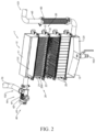
- FIGS. 1 to 5B an exhaust gas filtering apparatus 1 and a coating equipment 1000 according to a preferred embodiment of the present disclosure are illustrated.
- the exhaust gas filtering apparatus 1 is able to be used in conjunction with a coating body 2 of the coating equipment 1000.
- the coating body 2 of the coating equipment 1000 needs to discharge exhaust gas during operation, and the exhaust gas is guided through the exhaust gas filtering apparatus 1 to make the treated exhaust gas adapted for direct discharge towards the surrounding environment.
- the exhaust gas filtering apparatus 1 has an air inlet 101 and an air outlet 102, wherein the air inlet 101 is communicated with a coating chamber 300 of the coating body 2 of the coating equipment 1000, and the air outlet 102 is communicated with the external environment.
- the exhaust gas filtering apparatus 1 has a gas channel 100, wherein the air inlet 101 and the air outlet 102 are respectively located at two ends and communicated with the gas channel 100.
- the exhaust gas filtering apparatus 1 may include a mounting housing 10 and at least one filtering unit 20, wherein the filtering unit 20 may be detachably installed on the mounting housing 10.
- the mounting housing 10 may include a first mounting unit 11 and a second mounting unit 12, wherein the air inlet 101 is provided on the second mounting unit 12 of the mounting housing 10, and the air outlet 102 is provided on the first mounting unit 11 of the mounting housing 10.
- the filtering unit 20 is installed between the second mounting unit 12 and the first mounting unit 11.
- the gas channel 100 is formed in the second mounting unit 12, the first mounting unit 11, and the filtering unit 20.
- the exhaust gas from the reaction chamber sequentially passes through the air inlet 101, the second mounting unit 12, the filtering unit 20, the first mounting unit 11, and the air outlet 102.
- One of the filtering units 20 is detachably installed on the second mounting unit 12, one of the filtering units 20 is detachably installed on the first mounting unit 11, so that the filtering unit(s) 20 may be detached directly from the second mounting unit 12 and/or the first mounting unit 1 1 when the filtering unit(s) 20 needs to be replaced.
- the filtering unit 20 has a first mounting side and a second mounting side.
- the second mounting unit 12 is provided on a side of the first mounting side of the filtering unit 20, and the first mounting unit 11 is provided on a side of the second mounting side of the same filtering unit 20.
- the second mounting unit 12 is provided on a side of the first mounting side of one filtering unit 20, and the first mounting unit 11 is provided on a side of the second mounting side of another filtering unit 20.
- the first and second mounting sides of the filtering unit 20 may be two opposite or adjacent sides.
- the filtering unit 20 is lying transversely between the second mounting unit 12 and the first mounting unit 11, and the exhaust gas is guided along the first mounting side of the filtering unit 20 towards the second mounting side to through the filtering unit 20 to be filtered.
- the exhaust gas is able to pass through a position with a relatively large cross-sectional area of the filtering unit 20, which is beneficial for improving the work efficiency of the exhaust gas filtering apparatus 1.
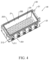
- the filtering unit 20 includes a side wall 21 and has a filtering chamber 200, wherein the side wall 21 surrounds to form the filtering chamber 200.
- the side wall 21 has a high end 211 and a low end 212, wherein the first mounting side is located at the high end 211 of the side wall 21, and the second mounting side is located at the low end 212 of the side wall 21.
- the filtering unit 20 further includes a filter material 22, wherein the filter material 22 is provided on the side wall 21 and located in the filtering chamber 200.
- Type of the filter material 22 may be selected according to needs, may be, but is not limited to, activated carbon filter material 22, or aluminium oxide filter material 22, or the like.
- adjacent filtering units 20 may be mounted detachably to each other, so as to facilitate the convenient replacement of one of the filtering units 20 when it needs to be replaced.
- all the filtering units 20 may be detached as a whole for replacement, or alternatively, an expectant filtering unit 20 may be detached individually.
- the filtering unit 20, installed adjacently to the second mounting unit 12 or the first mounting unit 11, is also detachably installed on the second mounting unit 12 or the first mounting unit 11 for easy replacement.
- the exhaust gas filtering apparatus 1 further includes at least one mounting component 30 adapted to connect the second mounting unit 12 and the filtering unit 20, or one filtering unit 20 and an adjacent filtering unit 20, or the first mounting unit 11 and the filtering unit 20.
- the mounting component 30 includes a mounting part 31 and a mounting accessory 32, wherein the mounting part 31 is detachably installed on the mounting accessory 32, the mounting part 31 or the mounting accessory 32 is adapted to be installed on the second mounting unit 12, and the mounting accessory 32 or the mounting part 31 is adapted to be installed on the first mounting unit 11, so as to enable detachable mounting between two components on which the mounting part 31 and the mounting accessory 32 are respectively installed.
- the mounting part 31 or the mounting accessory 32 of the mounting component 30 may be provided at the peripheral position of the side wall 21 or on the side wall 21 of the filtering unit 20, or at the peripheral position or side wall of the second mounting unit 12 and the first mounting unit 11.
- oppositely provided mounting parts 31 may be mounted on the mounting accessory 32 to limit displacement of two filtering units 20, so as to avoid the two filtering units 20 separate from each other.
- oppositely provided mounting parts 31 may be mounted on the mounting accessory 32 to limit displacement of the filtering unit 20 and the second mounting unit 12, so that the filtering unit 20 and the second mounting unit 12 are securely mounted and connected.
- oppositely provided mounting parts 31 may be mounted on the mounting accessory 32 to limit displacement of the filtering unit 20 and the first mounting unit 11, so that the filtering unit 20 and the first mounting unit 11 are securely mounted and connected.
- the mounting part 31 and the mounting accessory 32 of the mounting component 30 may be provided in a form of buckles matching with each other, may be plural in number, and may be different in type.
- a type of mounting part 31 and mounting accessory 32 are implemented as a permanent seat and a flippable buckle.
- the buckle is flipped in a direction away from the permanent seat, so that the permanent seat and the buckle are separated from each other.
- the mounting part 31 and the mounting accessory 32 need to be fixedly connected, the buckle is flipped towards the direction of the permanent seat, so that the buckle snaps into the permanent seat.
- Another type of mounting part 31 and mounting accessory 32 are implemented as a permanent seat and a hook, respectively.
- the filtering unit 20 on which the mounting part 31 is mounted and the filtering unit 20 on which the mounting accessory 32 is mounted may be locked with each other.
- the filtering unit 20 on which the mounting part 31 is mounted and the filtering unit 20 on which the mounting accessory 32 is mounted may be unlocked with each other.
- both the above two types of mounting parts 31 and mounting accessories 32 are used, and explanation is provided with the installation of two filtering units 20 as an example.
- one mounting part 31 may be located on the second mounting side of one filtering unit 20
- one mounting accessory 32 may be located on the first mounting side of the other filtering unit 20
- the mounting part 31 and the mounting accessory 32 are able to be aligned with each other, so that the mounting part 31 may be engaged with the mounting accessory 32 during the process of aligning the two filtering units 20 with each other.
- the mounting accessory 32 implemented as a flippable buckle on the side of one filtering unit 20, is flipped to be engaged with the mounting part 31 on the side of the other filtering unit 20.
- the mounting component 30 may further include another set of mounting part 31 and mounting accessory 32, wherein the mounting part 31 may be implemented as a bolt, the mounting accessory 32 may be implemented as a mounting hole, and after one filtering unit 20 is aligned and mounted on another filtering unit 20, or after the filtering unit 20 is aligned and mounted on the second mounting unit 12 or the first mounting unit 11, the mounting part 31 and the mounting accessory 32 are screwed, so as to fasten the adjacent filtering units 20, or fasten the filtering unit 20 and the second mounting unit 12 or the first mounting unit 11.
- the second mounting unit 12 and/or the first mounting unit 11 of the exhaust gas filtering apparatus 1 may be fixedly provided on the coating equipment 1000, so that the filtering unit 20 may be mounted on the coating equipment 1000 through mounting between the filtering unit 20 and the second mounting unit 12 and/or the first mounting unit 11.
- the first mounting unit 11 may be located below the second mounting unit 12.
- the air inlet 101 is located on a side of the first mounting unit 11.
- the air outlet 102 is located on a side of the second mounting unit 12.
- the gas channel 100 extends from the air inlet 101 from bottom to top to the air outlet 102.
- the exhaust gas filtering apparatus 1 may include a monitoring unit 40, wherein the monitoring unit 40 may be used to monitor the effectiveness of the filtering unit 20.
- the monitoring unit 40 may be located behind the filtering unit 20 to allow exhaust gas to pass through the monitoring unit 40 after being treated by the filtering unit 20.
- the monitoring unit 40 may include at least one detecting module 41 and at least one indicating module 42, wherein the detecting module 41 is provided in the gas channel 100 and behind the filtering unit 20, so as to allow exhaust gas to pass through the detecting module 41 after being filtered by the filtering unit 20.
- the detecting module 41 is used to detect a specific substance in the exhaust gas. When the detecting module 41 detects the specific substance in the exhaust gas exceeds a certain amount, the indicating module 42 may give an indication.
- the detecting module 41 and the indicating module 42 may be the same substance, such as a type of reagent that may chemically react with the specific substance in the exhaust gas and indicate by discoloration.
- one filtering unit 20 is used to filter a harmful gas A in the exhaust gas. After being filtered by the filtering unit 20, the harmful gas A in the exhaust gas has been removed or below a certain content. However, if the harmful gas A or more than the certain content of the harmful gas A is detected through the detecting module 41, and the indicating module 42 gives a relevant indication, it demonstrates that, the filter material 22 in the corresponding filtering unit 20 has been ineffective and needs to be replaced.
- the number of the detecting module 41 and the indicating module 42 may be set according to the requirements, for example, when the number of the filtering unit 20 is two or more, and the filter materials 22 inside the filtering units 20 are not the same, one detecting module 41 and one indicating module 42 may be used to indicate whether the corresponding filtering unit 20 is ineffective.
- the detecting module 41 is provided at the position of the air outlet 102, and the filtered exhaust gas is discharged outward after passing through the detecting module 41.
- the detachment and mounting of the filtering unit 20 relative to the second mounting unit 12 or the first mounting unit 11 do not affect the detecting module 41 and the indicating module 42.
- the detecting module 41 and the indicating module 42 may also be detachably mounted at the position of the air outlet 102, respectively, to facilitate the replacement of the detecting module 41 and the indicating module 42.
- the monitoring unit 40 may be a communicable equipment that may send information to another electronic equipment, such as, a production management equipment, a mobile electronic equipment, etc., to prompt the user to replace the equipment in time.
- the monitoring unit 40 may further include a processing module 43, wherein the detecting module 41 is communicatively connected to the processing module 43, and the indicating module 42 may be communicatively connected to the processing module 43.
- the processing module 43 is able to predetermine whether the filtering unit 20 is about to be ineffective based on the data detected by the detecting module 41.
- the indicating module 42 is able to give an indication in advance to reduce the possibility of exhaust gas not meeting environmental protection requirements being discharged outward.
- the processing module 43 sends an instruction to the indicating module 42, which may send a prompt in advance before nine forty.
- the monitoring unit 40 is implemented to include aluminium oxide treated with a special chemical reagent, which indicates whether the filter material 22 in the filtering unit 20 is ineffective through a change in color.
- the monitoring unit 40 may form an observation window 44, so that a user may observe the color change of the aluminum oxide inside the monitoring unit 40 through the observation window 44.
- the first mounting unit 11 forms a first accommodating chamber 110 communicated with the filtering chamber 200 of the filtering unit 20 and the air outlet 102.
- the exhaust gas passed through the filtering unit 20 converges at the first mounting unit 11, then leaves the first mounting unit 11 through the air outlet 102, and thereafter, passes through the detecting module 41 and the indicating module 42.
- the second mounting unit 12 forms a second accommodating chamber 120 communicated with the filtering chamber 200 of the filtering unit 20 and the air inlet 101.
- the exhaust gas from the air inlet 101 converges at the position of the second accommodating chamber 120 of the second mounting unit 12 and enters the filtering unit 20 upwards.
- the exhaust gas filtering apparatus 1 has a liquid outlet 103, wherein the liquid outlet 103 is provided on and at a lower position of the second mounting unit 12, so that the liquid condensed on the inner wall of the second mounting unit 12 or at the filtering unit 20 located above the second mounting unit 12 is able to be discharged through the liquid outlet 103, to avoid gathering at the second mounting unit 12 to affect the passage of the exhaust gas.
- the temperature of the exhaust gas from the coating equipment 1000 may be at a higher level than the ambient temperature of the exhaust gas filtering apparatus 1. Therefore, when the exhaust gas contains moisture therein, it will condense into a liquid when encountering the inner wall of the second mounting unit 12 or the filtering unit 20, and move towards the position of the liquid outlet 103 under the action of gravity.
- the liquid outlet 103 is configured to be openable or closable, for example, may be provided with a valve to discharge condensate regularly.
- the exhaust gas filtering apparatus 1 further includes at least one sealing ring 50 provided between the filtering unit 20 and the filtering unit 20, or between the filtering unit 20 and the second mounting unit 12, or between the filtering unit 20 and the first mounting unit 11.
- the sealing ring 50 may be detachably installed.
- the sealing ring 50 is provided at the connection edge position between the filtering unit 20 and the filtering unit 20, or at the connection edge position between the filtering unit 20 and the second mounting unit 12, or at the connection edge position between the filtering unit 20 and the first mounting unit 11.
- the filtering unit 20 has a filtering inlet 201 and a filtering outlet 202 respectively located on two sides of and communicated with the filtering chamber 200, wherein the sealing ring 50 is provided at the position of the side wall 21 forming the filtering inlet 201 or at the position of the side wall 21 forming the filtering outlet 202.
- the first mounting unit 11 is provided on the side of the filtering outlet 202 of the filtering unit 20.
- the second mounting unit 12 is provided on the side of the filtering inlet 201 of the filtering unit 20.
- the cross-section of the filtering unit 20 may be, but is not limited to, a rectangle, a circle, or a polygon.
- the shape of the filtering inlet 201 of one filtering unit 20 and the shape of the filtering outlet 202 of the other filtering unit 20 match each other to facilitate sealability between the two.
- the shape of the filtering outlet 202 of one filtering unit 20 and the shape of a mounting opening 1101 of the first mounting unit 11 match each other to facilitate the sealability between the two.
- the shape of the filtering inlet 201 of one filtering unit 20 and the shape of a mounting opening 1201 of the second mounting unit 12 match each other to facilitate the sealability between the two.
- the exhaust gas filtering apparatus 1 may also include an air inlet pipe 60 and an air outlet pipe 70 respectively provided at the position of the air inlet 101 and of the air outlet 102, wherein the air inlet pipe 60 is adapted to communicate the coating equipment 1000 with the second mounting unit 12, and the air outlet pipe 70 is adapted to communicate an external discharge equipment and the first mounting unit 11.
- the exhaust gas filtering apparatus 1 may further include a corrugated pipe 80 provided between the air inlet pipe 60 and the second mounting unit 12.
- the exhaust gas is transported from top to bottom through the air inlet pipe 60 and the corrugated pipe 80 to the position of the air inlet 101, and then, passes through the filtering unit 20 from bottom to top to be filtered, and thereafter, leaves through the air outlet pipe 70.
- the filtering units 20 has a number of three, which are respectively implemented from top to bottom as an aluminium monoxide filter box, an activated carbon filter box, and a honeycomb activated carbon filter box, that is, the exhaust gas sequentially passes through the honeycomb activated carbon filter box, the activated carbon filter box, and the aluminium monoxide filter box.
- the filter material 22 may further include an activated carbon sponge provided at the positions of the filtering inlet 201 and the filtering outlet 202 of the filtering unit 20, which may prevent a pollutant with a relatively large particle from on the one hand, entering the filtering chamber 200, and on the other hand, leaving the filtering chamber 200.
- the filtering unit 20 further includes at least one carrier plate 23, wherein the carrier plate 23 is supported on the side wall 21 and is provided as hollow to enable the exhaust gas to pass smoothly, and the filter material 22 may be supported on the carrier plate 23. It should be understood that, the type and construction of the filter material 22 may be selected according to needs. The types of filter materials 22 within the same filtering unit 20 may be different. The filter material 22 may have a gap formed inside to facilitate the passage of exhaust gas.
- FIG. 6 which illustrates an exhaust gas filtering apparatus 1 according to another preferred embodiment of the present disclosure.
- the mounting component 30 of the exhaust gas filtering apparatus 1 is implemented as a hook type.
- the mounting between two filtering units 20 is explained as an example.
- the side wall 21 forming the filtering inlet 201 part of the filtering unit 20 extends outward to form a permanent seat as the mounting part 31 of the mounting component 30, and another filtering unit 20 is provided with the mounting accessory 32 near the filtering outlet 202.
- the mounting of the two filtering units 20 may be achieved by directly hanging the mounting accessory 32 onto the mounting part 31.
- the mounting part 31 is hung on the mounting accessory 32, when aligning the filtering inlet 201 of one filtering unit 20 with the filtering outlet 202 of another filtering unit 20, and gradually aligning the mounting part 31 with the mounting accessory 32, so that the position of the filtering inlet 201 fits that of the filtering outlet 202.
- FIG. 7 illustrates an exhaust gas filtering apparatus 1 according to still another preferred embodiment of the present disclosure.
- the mounting housing 10 and the filtering unit 20 in the exhaust gas filtering apparatus 1 are provided in the same direction, such as in a vertical direction.
- the second mounting unit 12 and the first mounting unit 11 of the mounting housing 10 are respectively located on the opposite first mounting side and second mounting side of the filtering unit 20.
- the second mounting unit 12 and the first mounting unit 11 of the mounting housing 10 in the exhaust gas filtering apparatus 1 are located on adjacent two sides of the filtering unit 20, respectively.
- the relative positions of the mounting housing 10 and the filtering unit 20, or of a plurality of filtering units 20, may be arranged according to the requirements of the gas channel 100.
- the filtering unit 20 may be connected directly to the air inlet pipe 60 and the air outlet pipe 70, that is, the exhaust gas filtering apparatus 1 may not include the mounting housing 10.
- the filtering unit 20 may have a number of three, and the filtering unit 20 located in the middle is detachably connected to the adjacent two filtering units 20, respectively, so that it is replaceable.
Landscapes
- Chemical & Material Sciences (AREA)
- Chemical Kinetics & Catalysis (AREA)
- General Chemical & Material Sciences (AREA)
- Engineering & Computer Science (AREA)
- Materials Engineering (AREA)
- Mechanical Engineering (AREA)
- Metallurgy (AREA)
- Organic Chemistry (AREA)
- Analytical Chemistry (AREA)
- Oil, Petroleum & Natural Gas (AREA)
- Filtering Of Dispersed Particles In Gases (AREA)
- Treating Waste Gases (AREA)
Applications Claiming Priority (2)
| Application Number | Priority Date | Filing Date | Title |
|---|---|---|---|
| CN202011575631.8A CN112843976A (zh) | 2020-12-28 | 2020-12-28 | 尾气过滤装置和镀膜设备 |
| PCT/CN2021/134978 WO2022142990A1 (zh) | 2020-12-28 | 2021-12-02 | 尾气过滤装置和镀膜设备 |
Publications (2)
| Publication Number | Publication Date |
|---|---|
| EP4268931A1 true EP4268931A1 (de) | 2023-11-01 |
| EP4268931A4 EP4268931A4 (de) | 2024-05-01 |
Family
ID=75997449
Family Applications (1)
| Application Number | Title | Priority Date | Filing Date |
|---|---|---|---|
| EP21913731.2A Withdrawn EP4268931A4 (de) | 2020-12-28 | 2021-12-02 | Abgasfiltervorrichtung und beschichtungsanlage |
Country Status (5)
| Country | Link |
|---|---|
| US (1) | US20240035156A1 (de) |
| EP (1) | EP4268931A4 (de) |
| JP (1) | JP7743520B2 (de) |
| CN (1) | CN112843976A (de) |
| WO (1) | WO2022142990A1 (de) |
Families Citing this family (1)
| Publication number | Priority date | Publication date | Assignee | Title |
|---|---|---|---|---|
| CN112843976A (zh) * | 2020-12-28 | 2021-05-28 | 江苏菲沃泰纳米科技股份有限公司 | 尾气过滤装置和镀膜设备 |
Family Cites Families (21)
| Publication number | Priority date | Publication date | Assignee | Title |
|---|---|---|---|---|
| JPS5827631U (ja) * | 1981-08-10 | 1983-02-22 | 中井 俊晴 | 移動可能な排気処理装置 |
| JP3783088B2 (ja) * | 1996-07-04 | 2006-06-07 | 四国化工機株式会社 | フィルタユニット |
| DE102005043791A1 (de) * | 2005-09-13 | 2007-03-15 | Mann + Hummel Gmbh | Einrichtung zur Reinigung von Luft |
| ES2351335B1 (es) * | 2010-10-26 | 2011-11-15 | Servifiltro, S.L. | unidad de filtración de aire a base de módulos. |
| US9370740B2 (en) * | 2013-01-31 | 2016-06-21 | Oneida Air Systems, Inc. | Modular stacking filter system |
| CN205055679U (zh) * | 2015-08-12 | 2016-03-02 | 浙江宇视科技有限公司 | 空气过滤装置 |
| CN106621745A (zh) * | 2016-12-26 | 2017-05-10 | 江南大学 | 一种竹节串联组合式抽真空尾气净化管 |
| CN206830271U (zh) * | 2017-02-13 | 2018-01-02 | 安徽新态环保科技有限公司 | 可拆卸式柴油车尾气后处理装置 |
| CN206631413U (zh) * | 2017-04-10 | 2017-11-14 | 上海兰宝环保科技有限公司 | 一种有机废气净化治理设备 |
| US10780385B2 (en) * | 2017-05-30 | 2020-09-22 | General Electric Company | System and method for condition-based monitoring of filters |
| MY201789A (en) * | 2017-10-26 | 2024-03-18 | First Solar Inc | Systems and methods for vaporization and vapor distribution |
| CN108906117A (zh) * | 2018-07-06 | 2018-11-30 | 郑州三希新材料科技有限公司 | 一种新型可视变色的空气净化材料及其制备方法 |
| CN109126318A (zh) * | 2018-09-25 | 2019-01-04 | 蔡少青 | 一种空气净化器除尘滤网 |
| CN210473488U (zh) * | 2019-06-26 | 2020-05-08 | 上海奎欣电子科技有限公司 | 一种新型全自动净化器 |
| CN211345609U (zh) * | 2019-09-09 | 2020-08-25 | 武汉洁琅环保科技有限公司 | 一种堆叠式桌面空气净化器 |
| CN110904429A (zh) * | 2019-12-04 | 2020-03-24 | 江苏菲沃泰纳米科技有限公司 | 镀膜装置的镀膜系统 |
| CN211753304U (zh) * | 2019-12-30 | 2020-10-27 | 李峰 | 带报警提示功能的纳米级气体除水除尘净化过滤装置 |
| CN211886117U (zh) * | 2020-03-17 | 2020-11-10 | 龙鳞(深圳)新材料科技有限公司 | 一种尾气处理系统及镀膜设备 |
| CN213467104U (zh) * | 2020-07-17 | 2021-06-18 | 上海沼鑫环保新能源科技有限公司 | 一种垃圾填埋气过滤箱 |
| DE202020104163U1 (de) * | 2020-07-20 | 2020-07-29 | San Ford Machinery Co., Ltd. | Montierter Luftfilter |
| CN112843976A (zh) * | 2020-12-28 | 2021-05-28 | 江苏菲沃泰纳米科技股份有限公司 | 尾气过滤装置和镀膜设备 |
-
2020
- 2020-12-28 CN CN202011575631.8A patent/CN112843976A/zh active Pending
-
2021
- 2021-12-02 US US18/265,780 patent/US20240035156A1/en active Pending
- 2021-12-02 WO PCT/CN2021/134978 patent/WO2022142990A1/zh not_active Ceased
- 2021-12-02 JP JP2023537656A patent/JP7743520B2/ja active Active
- 2021-12-02 EP EP21913731.2A patent/EP4268931A4/de not_active Withdrawn
Also Published As
| Publication number | Publication date |
|---|---|
| US20240035156A1 (en) | 2024-02-01 |
| WO2022142990A1 (zh) | 2022-07-07 |
| CN112843976A (zh) | 2021-05-28 |
| EP4268931A4 (de) | 2024-05-01 |
| JP7743520B2 (ja) | 2025-09-24 |
| JP2024500450A (ja) | 2024-01-09 |
Similar Documents
| Publication | Publication Date | Title |
|---|---|---|
| US10315151B2 (en) | Exhaust treatment apparatus and container apparatus | |
| WO2008045972A3 (en) | Precursor delivery system | |
| EP4268931A1 (de) | Abgasfiltervorrichtung und beschichtungsanlage | |
| CN212700928U (zh) | 过滤装置及全地形车 | |
| KR101141549B1 (ko) | 반도체 및 lcd용 배기가스 점검구 | |
| CN211488988U (zh) | 一种通风柜 | |
| CN210448390U (zh) | 过滤设备 | |
| CN213286187U (zh) | 一种压机烟气高效安全湿处理系统 | |
| CN113750670B (zh) | 一种用于3d打印的净化装置 | |
| CN216537775U (zh) | 一种具有监测功能的工业废气净化处理装置 | |
| CN222491427U (zh) | 酒精供应装置及清洁设备 | |
| CN111932838B (zh) | 一种基于信息技术的化工实验异状自识别的警报系统 | |
| CN111375281A (zh) | 气体处理设备 | |
| CN217055265U (zh) | 供氧装置 | |
| CN221267609U (zh) | 一种工业废气吸附处理装置 | |
| CN218076990U (zh) | 一种环形废气收集装置 | |
| CN223782657U (zh) | 一种储罐氮封系统用组合装置 | |
| CN214647468U (zh) | 一种应用于冷藏车厢的低碳分体式冷机组 | |
| CN219314580U (zh) | 一种干法焦炉煤气脱硫废液硫磺回收装置 | |
| CN214553401U (zh) | 一种用于反应釜的安全生产装置 | |
| CN216764325U (zh) | 一种炭黑原料油油气收集装置 | |
| KR100311145B1 (ko) | 반도체 장비의 파우더 포집장치 | |
| CN212442368U (zh) | 一种实验室高纯惰性气体供气吹扫装置 | |
| CN223728317U (zh) | 一种化工设备用安全监控警报装置 | |
| CN210434229U (zh) | 水淋装置 |
Legal Events
| Date | Code | Title | Description |
|---|---|---|---|
| STAA | Information on the status of an ep patent application or granted ep patent |
Free format text: STATUS: THE INTERNATIONAL PUBLICATION HAS BEEN MADE |
|
| PUAI | Public reference made under article 153(3) epc to a published international application that has entered the european phase |
Free format text: ORIGINAL CODE: 0009012 |
|
| STAA | Information on the status of an ep patent application or granted ep patent |
Free format text: STATUS: REQUEST FOR EXAMINATION WAS MADE |
|
| 17P | Request for examination filed |
Effective date: 20230628 |
|
| AK | Designated contracting states |
Kind code of ref document: A1 Designated state(s): AL AT BE BG CH CY CZ DE DK EE ES FI FR GB GR HR HU IE IS IT LI LT LU LV MC MK MT NL NO PL PT RO RS SE SI SK SM TR |
|
| DAV | Request for validation of the european patent (deleted) | ||
| DAX | Request for extension of the european patent (deleted) | ||
| A4 | Supplementary search report drawn up and despatched |
Effective date: 20240404 |
|
| RIC1 | Information provided on ipc code assigned before grant |
Ipc: C23C 16/44 20060101ALI20240327BHEP Ipc: B01D 46/30 20060101ALI20240327BHEP Ipc: B01D 46/00 20220101ALI20240327BHEP Ipc: B01D 53/02 20060101ALI20240327BHEP Ipc: B01D 53/00 20060101AFI20240327BHEP |
|
| STAA | Information on the status of an ep patent application or granted ep patent |
Free format text: STATUS: THE APPLICATION HAS BEEN WITHDRAWN |
|
| 18W | Application withdrawn |
Effective date: 20241115 |